AIAA-92-3494. Modal Simulation of Gearbox Vibration. With Experimental Correlation. Fred K. Choy and Yeefeng F. Ruan. The University of Akron. Akron, Ohio.
AD-A260 134 NASA
I11iIN1111;11111111111111!AVSCOM
Technical Memorandum 105702 AIAA-92-3494
Technical Report 92-C-018
Modal Simulation of Gearbox Vibration With Experimental Correlation
Fred K. Choy and Yeefeng F. Ruan The University of Akron Akron, Ohio and James J. Zakrajsek and Fred B. Oswald NationalAeronautics and Space Administration Lewis Research Center Clevelan4 Ohio
DTIC
SELE-CTE
JAN291993
Prepared for the 28th Joint Propulsion Conference and Exhibit cosponsored by the AIAA, SAE, ASME, and ASEE Nashville, Tennessee, July 6-8, 1992
W
US ARMY
.....
SYMM~S COMMAND
93-01692
98
1 28 048
MODAL SIMULATION OF GEARBOX VIBRATION WITH EXPERIMENTAL CORRELATION Fred K. Choy, Yeefeng F. Ruan Department of Mechanical Engineering The University of Akron Akron, Ohio 44325
Accesion For NTIS CRA&I DTIC TAB Unannounced Justification
...........
By .............................
and
................
Distribution!
James J. Zakrajsek, Fred B. Oswald National Aeronautics and Space Administration Lewis Research Center Cleveland, Ohio 44135
Availability Codes Avail and I or Special Dist
1
DTIC QUALITY INSPECHD 31 Abstract
{Bel
rotor modal displacement of (YC, Yce)
A newly developed global dynamic model was used to simulate the dynamics of a gear noise rig at the NASA Lewis Research Center. Experimental results from the test rig were used to verify the analytical model. In this model, the number of degrees of freedom of the system are reduced by transforming the system equations of motion into modal coordinates. The vibration of the individual gear-shaft systems is coupled through the gear-mesh forces. A threedimensional bearing model was used to couple the casing structural vibration to the gear rotor dynamics. The system of modal equations is solved to predict the resulting vibration at several locations on the test rig. Experimental vibration data were measured at several running speeds and were compared to the predictions of the global dynamic model. There was excellent agreement between the analytical and experimental vibration results.
[CbI
bearing damping matrix
[J
[$]T
[Cb]
[Cb]
] T [I]TCb] [tC[
[CJ
casing structure damping matrix
[Uj
[{$jT [Cj [
(D)
rotor modal displacement of Z
{De}
casing modal displacement of (Zc, Zje)
(Dr}
rotor modal displacement of 9t
F
gear force
{F(t))
external and mass imbalance excitations
{Fc(t))
force acting on casing structure
{FG(t))
nonlinear gear forces, through gear mesh coupling
Nomenclature {A)
rotor modal displacement of (X, 0z)
(Ac)
casing modal displacement of (Xc, Xje)
(F 3 (t))
shaft bow force = [K.] {Wr}
(B)
rotor modal displacement of (Y, O7 )
[GAJ
rotor angular acceleration
[(A]
[.T 4 1U.
[GA] [I]I
friction coefficient between the gear
i
tooth surface
,I
[4'] I• [..] ...KA]
[KAI"
orthonormal mode orthonormal mode of casing
, Iý[0cI
1/2 {[KbJ•_+.JKby]}
[WI
1[
1 [HA@]T
[KA [AJ[wJ 1
critical speeds of each rotor critical speeds of casing
lateral cross-coupling bearing axial and stiffness
-
"Introduction
[
Large vibrations in gear transmission systems excessive wear and crack formation in gear teeth, which results in premature gear failure.
c]T Kbcauses [K.....[...
[KJ
casing structure stiffness
[Ka]
shaft bow stiffness
[Ml
mass matrix of rotor
[MC]
mass matrix of casing structure
R
pitch radius of gear
{[W]}
generalized displacement vector of rotor
{[Wc]}
generalized displacement vector of casing
{Wr}
genearlized displacement vector of rotor
X,Y,Z
displacement vectors
a
angle of orientation
With the need for higher operating speeds and power from transmission systems, the problem of excessive vibration becomes even more critical. In order to insure smooth and safe operation, it is necessary to understand the dynamics of the gear transmission system. Two areas of research in the dynamics of gear transmission systems are (1) analytical simulation and (2) experimental testing. There is a great deal of literature on the vibration analysis of a single gear stage. 1 4 Some work has been done on multistage gear vibration, 7 "9 but very limited work1 3 1' 1 has been done on the dynamic analysis of gearbox vibration. Considerable effort has been devoted to experimentally studying gear dyanmics1 2 1 4 and localized vibration effects on gear teeth.1 5 A few studies have been conducted to correlate analytically predicted and experimentally measured gearbox vibrations. This paper correlates the experimental results
obtained from the test rig at the NASA Lewis
o
Eq. (5)
9
generalized displacement
0
torsional rotational vector
0,09y
lateral rotational vectors
Research Center with predictions from an analytical model developed by using the modal synthesis method.7 The major excitations of the rotor system include mass imbalance, shaft residual forces 1 6 and gear-tooth bow, nonlinear gear-mesh frictional effects. 1 4 The vibratory motion between the rotor and the casing is coupled
2
through the support bearing in the lateral and axial directions." Gearbox mode shapes and vibration predictions from the analytical model are compared to those obtained from experimental testing.
The motions of the individual shafts are coupled to each other through the gear-mesh forces (Fig. 1) and to the casing through bearing stiffness [Kb] and damping [CbI. The equations of motion for the casing can be written as + [Cb]{Wc - W} + lKb]{WC W)
Analytical Procedure Development of Equations of Motion The equations of motion for each system can be written in matrix form as
IMI
{*} +
+ L jrcl +ear-shaft
(3)
{(*}
where [Mc] is the mass matrix of the casing struc-
c + [GA] XW) + [Cb] {W- ~Wr + [Kb] (W - W + C[K' , (WUi (t
[G,]
+ [Kc](Wc} = {IF't,
represents the generalized displaceture; ment {Wj} vector of the casing structure:
MOf~t) + {FG
(Xe) I)
(1)
(xc*)
where [M] is the mass matrix of the rotor (iner-
(wI
(YCO)
tia), {W} is the generalized displacement vector consisting of the three displacement vectors X,Y,Z with the corresponding lateral Ox, Oy, and torsional Ot rotational vectors as
(ZC) (ZcO) [CJ is the casing structure damping matrix; [Kc] is the casing structure stiffness; and {FC(t)} is the force acting on the casing structure. The nonlinear gear forces for the kth individual shaft system, using nonlinear gear stiffness and gear-tooth friction,14 are given as x-force
(X) ) =
(Y(c)
=
(W) (Z)
('i) Vj I
n
and where [Gl is the gyroscopic force; [GA] is the
FGxk =
rotor angular acceleration; [Chi is the bearing direct and cross-coupling damping, [Kb] is the bearing axial and lateral cross-coupling stiffness; 1 1 {W - Wj} is the casing vibration; [K] is the shaft bow stiffness; {W - Wr} is the shaft residual bow; {F(t)} is the external and masst[COS imbalance excitation; and {FG(t)} is the nonlinear gear force through gear-mesh coupling. y-force For a multiple gear-shaft system, the equations of motion (1) are repeated for each shaft.
3
i=1, i ok
Ktki [-Rcici - Re•kck + (Xi
-
Xck)cos aki
+ (Yi
-
Yck)sin aki]
aij + (sign)(p)(sin akd]
(5)
n
L
FGyk =
[ KtkiVRcic +~, ii
where w is the rotor critical speed. Similarly, a of orthogonality conditions can be derived for the casing equation of [Ke] {W} + [Cc] {Wc} + [Kc] (Wc} = 0 (12)
-set -
-X(
RPk9 ck
with the orthonormal mode [-fc] such that "+ (Yci - Yck)sin aki] [sin aki + (sign)(p)(cos aki)]
4
and torsional
= [I]
(13)
c]T [Cc][# c] = [pc]
(14)
*jT [KJ [,j = nC
FGtk=
(15)
where wc is the casing critical speed. Using modal transformation' by letting
lR{Ktki [(-Rci~ci - Rck~ck) i=l, i wak
[-P]
+ (Xci - Xck)cos a
{OI(A}
+ (Yci -- Yd)sin alld#'
(7)
["II {B} [0yo] {B} [$,] (D} *tI {Dr}
Modal Transformation
and
The equation of motion for the undamped
Itl
rotor system is
{Ac
L=CJ
=
0
(8)
[#cx*l{AAc
with the average bearing support stiffness from the x-y direction given as [KAI = .'{[Kbr] + [KbY]}
[ c] {Bc} (9)
=
[Ocyo] (Bc}
tocus] {Dc)
and [w2 ]
(17)
0Ics] {Dc}
The orthogonality condition for the orthonormal modes [] are m ]T M[0][ = [1] (10)
[IT [K6 + KAJ [0] =
(16)
{W} =
gear and (7 where R is the pitch radius of the is the coefficient of friction between the gear tooth surface and "SIGN" is the unity sign function to provide the sign change when the mating teeth pass the pitch point.' 4
[M]{W} + [[KJ + [KAI]{W}
(A}
the equations of motion for the rotor (Eq. (1)) can be transformed as
(11)
4
housing. The measured three-dimensional mode shapes are presented in Fig. 4. The dynamic vibration measurements consist of data collected
R] M + Al]M + [UA1M + Al]M - [Kb - KA] { Z} + [ 1T [Cb[•4J {Zc} (18)
from accelerometers placed at three of the nodes on the surface of the casing. They were chosen such that vibration was measured in all three
+ [W2 ] {Z} - [4]T [Kb] 14c] {Z} [@]T {F(t) + FG (t) + Fs(t)}
-
directions, X,Y, and Z. A dynamic signal analyzer was used to compute the frequency spectra of the vibration. The experimental frequency spectra are shown in Figs. 5(a), 6(a), and 7(a) for the X-, Y-, and Z-directions, respectively, at a numof different operating speeds.
and for the casing (Eq. (3)) as [I] (Z) + IUC] {ZJ + [W]2 {Z} [C {j + [RbI {Zc} + F['b] 1T {C}M - [T [Cb [$]{7Z} {ber [Kb][4']{Z} [4] T [Cb]
[LOC{JtC
(19) (19
Discussion and Correlation of Results
J
where The measured mode shapes, shown in Fig. 4 represent the major vibration modes of the gear noise rig in the 0- to 3-kHz region. Although these modes are only a small portion of the total modes of the system, they represent the major portion of the total global vibration of the system. In order to produce a compatible analytical simulation of the test apparatus, a similar set of modes was predicted by a finite-element model of the gearbox structure. This model serves as the basis for predicting casing vibrations in the overall global dynamic model. Of the 25 modes found by the analytical model in the 0- to 3-kHzfrequency region, the 8 dominant modes were used to represent the gearbox dynamic characteristics. These simulated modes are shown in Fig. 8. The natural frequencies of the predicted modes are within 5 percent of the measured modes (Table 2). Also, the predicted mode shapes are very similar to the experimental modes shapes (Fig. 4). The good correlation of between the analytical model and the measurements confirms the accuracy of the dynamic representation of the test gearbox using only a limited number of modes.
{A}
{Ac) {B} {Z} =
{ {Z}
{D} Dt}
(20) J
DJ}
Experimental Study The gear noise rig (Fig. 2) was used to measure the vibration, dynamic load, and noise of a geared transmission. The rig features a simple gearbox (Fig. 3) containing a pair of parallel axis gears supported by rolling element bearings. A 150-kW (200-hp), variable-speed electric motor powers the rig at one end, and an eddy-current dynamometer applies power-absorbing torque at the other end. The test gear parameters are given in Table 1. Two sets of experiments were performed on the gearbox; (1) experimental modal analysis and (2) dynamic vibration measurements during operation. In the experimental modal analysis, modal parameters, such as system natural frequencies and their corresponding mode shapes, were obtained through transfer function measurements by using a two-channel, dynamic signal analyzer and modal analysis software. For this experiment, 116 nodes were selected on the gearbox
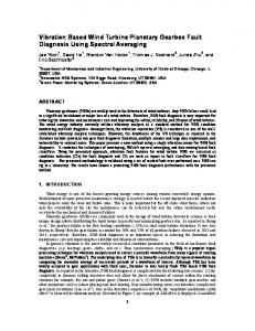
For the dynamic study of the gearbox vibration, it was found that during a slow roll (lowspeed run) of the gear-rotor assembly, a substantial residual bow (or eccentricity in the sleeve assembly) exists in the rotor system as shown by its large orbital motion in Fig. 9. Figure 9(a)
5
spectra at the running speeds of 1500 and 5500 rpm, respectively.
represents the orbit of the driver rotor at the gear location, and Fig. 9(b) represents that of the driven rotor. Note that the circular orbit in the driver rotor at low speed represents the residual bow deformation of the rotor. The elliptical orbit in the driven rotor is attributed to a combination of the residual bow effects and the vertical gear force from the torque of the driving rotor. In order to analytically simulate the influence of this effect, a residual bow of 2 mils (0.05 mm) is incorporated into the numerical model (Eq. (1)).
Figures 6 and 7 compare the predicted measured housing vibration spectra in the Y- and Zdirections, respectively. The results of the comparison are the same as those presented for the housing vibration in the X-direction (Figs. 5(a) and (b)). Acutal values of the components in the spectra were not always in good agreement; however, the general trends for the predicted and measured housing vibration spectra were very similar. Also, as seen in Fig. 7(b) at the 1500-rpm speed, the model predicts the second and third harmonics of the gear-mesh frequency. As shown in Fig. 7(a), the measured vibration confirms the presence of these two harmonics at the 1500-rpm running speed.
The frequency spectra of the analytically predicted casing vibration in the X-, Y-, and Zdirections are presented in Figs. 5(b), 6(b), and 7(b), respectively. As seen in Fig. 5(a), the experimental casing vibration in the X-direction shows a major vibration component at the gearmesh frequency (28 times shaft speed) at each rotational speed. A closer examination of this excited frequency component shows that two major vibration peaks occur at the running speeds of 1500 rpm (at a tooth pass frequency of 700 Hz) and 5500 rpm (at a tooth pass frequency of 2560 Hz). These peaks are a result of the tooth pass frequency exciting two of the major natural frequencies of the housing, namely the 658- and 2536-Hz modes. The presence of other modes can be seen; however, the 658- and 2536-Hz modes, when excited by the gear-mesh frequency, dominate the spectra.
Conclusions A newly developed global dynamic model was used to simulate the dynamics of a simple transmission system. Predicted casing vibrations were compared to measured results from the gear noise test rig at the NASA Lewis Research Center. The conclusions of this study are summarized as follows: 1. The dynamics of the housing can be accurately modeled with a limited amount of analytically predicted, experimentally verified vibration modes of the structure.
Comparing the predicted vibration spectra with the measured spectra reveals that, although the actual amplitude values did not always agree, the general trends of the spectra were very similar. The predicted vibration spectra of the housing in the X-direction is shown in Fig. 5(b). A comparison of Figs. 5(a) and (b) shows that the predicted amplitude at the gear-mesh frequency at 1500 rpm is only 3 percent above the measured value. The comparison at 5500 rpm is not that close; the predicted amplitude is 38 percent below the measured value. If trends are compared, the predicted spectra show the same gear-mesh, frequency-induced excitation of the 658- and 2536-Hz modes as that found in the measured
2. The global dynamic model is capable of including in the analysis the effects of shaft residual bow or eccentricity. 3. Absolute values of the housing vibration predicted by the global dynamic model did not always agree with measured values. 4. The characteristics and trends of the housing vibration spectra predicted by the global dynamic model are the same or very similar to those found in the experimental data.
6
References
Review", Journal of Sound and Vibration, Vol. 121, No. 3, Mar. 22, 1988, pp. 383-411.
1. August, R., and Kasuba, R., "Torsional Vibrations and Dynamic Loads in a Basic Planetary Gear System", Journal of Vibration, Acoustic, Stress, and Reliability in Design, Vol. 108, No. 3, July 1986, pp. 348-353.
10. Choy, F.K., Ruan, Y.F., Zakrajsek, J.J., Oswald, F.B., and Coy, J.J., "Analytical and Experimental Study of Vibrations in a Gear Transmission", AIAA Paper-91-2019, June 1991.
2. Choy, F.K., Townsend, D.P., and Oswald, F.B., "Dynamic Analysis of Multimesh-Gear Helicopter Transmissions", NASA TP-2789, 1988.
11. Lim, T.C., Signh, R., and Zakrajsek, J.J., "Modal Analysis of Gear Housing and. Mounts", International Modal Analysis Conference, 7th, Vol. 2, Society of Experimental Mechanics, Bethel, CT, 1990, pp. 1072-1078.
3. Cornell, R.W., "Compliance and Stress Sensitivity of Spur Gear Teeth," Journal of Mechanical Design, Vol. 103, No. 2, Apr. 1981, pp. 447-459.
12. Lewicki, D.G., and Coy, J.J., "Vibration Characteristics of the OH-58A Helicopter Main Rotor Transmission", NASA TP-2705, 1987.
4. Lin, H., Houston, R.L. and Coy, J.J., "On Dynamic Loads in Parallel Shaft Transmissions 1: Modelling and Analysis," NASA TM-100108, December 1987.
13. Oswald, F.B., "Gear Tooth Stress Measurements on the UH-60A Helicopter Transmission", NASA TP-2698, 1987.
5. Mark, W.D., "The Transfer Function Method for Gear System Dynamics Applied to Conventional and Minimum Excitation Gear Designs", NASA CR-3626, 1982.
14. Rebbechi, B., Oswald, F.O., and Townsend, D.P., "Dynamic Measurements of Gear Tooth Friction and Load", NASA TM-103281, 1991.
6. Boyd, L.S., and Pike, J., "Epicyclic Gear Dynamics," AIAA Paper 87-2042, June 1986.
15. Townsend, D.P., and Bamberger, E.N., "Surface Fatigue Life of M5ONiL and AIS19310 Spur Gears and R C Bars", NASA TM-104496, 1991.
7. Choy, F.K., Tu, Y.K., Savage, M., and Townsend, D.P., "Vibration Signature Analysis of Multistage Gear Transmission", Journal of the Franklin Institute, Vol. 328, No. 2/3, 1991, pp. 281-299.
16. Boyd, L.S., and Pike, J.A., "Epicyclic Gear Dynamics", AIAA Journal, Vol. 27, No. 5, May 1989, pp. 603-609.
8. David, J.W., Mitchell, L.D., and Daws, J.W., "Using Transfer Matrices for Parametric System Forced Response", Journal of Vibration, Acoustics, Stress and Reliability in Design, Vol. 109, No. 4, Oct. 1987, pp. 356-360.
17. Choy, F.K., Townsend, D.P., and Oswald, F.B., "Experimental and Analytical Evaluation of Dynamic Load and Vibration of a 2240-KW Rotor craft Transmission", Journal of The Franklin Institute, Vol. 326, No. 5, 1989, pp. 721-735.
9. Osguven, H.N., and Houser, D.R., "Mathematical Models Used in Gear Dynamics-A
7
TABLE I. - TEST GEAR PARAMETERS
Standard involute, full-depth tooth Gear type .............. Number of teeth ................................ 28 Module, nun (diametrial pitch in."1 ) .............. 3.174(8) Face width, mm (in.) ........................ 6.35(0.25) Pressure angle, deg .............................. 20 1.64 Theoretical contact ratio ......................... 0.023 (0.0009) Driver modification amount, mm (in.) ......... 0.025(0.0010) Driven modification amount, mm (in.) ........ 24 Driver modification start, deg ....................... 24 Driven modification start, deg ...................... 1.35(0.053) Tooth-root radius, mm (in.) ................... AGMA class 13 Gear quality ......................... Nominal (100 percent) torque, N-m(in.-lb) ...... 71.77(635.25)
TABLE 2.-COMPARISON OF EXPERIMENTAL MEASURED AND ANALYTICAL MODELED NATURAL FREQUENICES Experimental, Hz
Analytical, Hz
Difference, percent
658 1049 1710 2000 2276 2536 2722 2962
658 1006 1762 2051 2336 1536 2752 3012
0 -4.1 3.0 2.6 2.6 0 1.1 1.7
aki -ww4O--
R-d Dynamometer- I piing
Tettag.
increaser,7
y
x kthStag.
z Figure 2.-Picture of gear noise rig.
Figure 1.- Geometry of gear force simulation.
Figure 3.-Test gearbox.
7 1 -Mode: M~od: Frequency, 658.37 Hz
2 Frequency, 1048.56 Hz
z
z
y
y
x
Frequency, 2535.95 Hz
Frequency, 22759.69 Hz
z
Made:?5
Mode: 6
Frequency, 2722.16 Hz
Frequency. 296.71 Hz
T
Figure C.-Gearbox experilmental mode shapes.
10
Major modes of housing NO 6 6---Gear-mesh
A-4
frequency
2 C. 0
7.
6000 =..2_
Hz
gear-mesh
______frequency
-45
0
0 ----
]
C 3=0 /
I
25 1500oo
.. •.a.,.
-
700-Hz geamesh frequency
~.. ,
-
(a)Experimental. Major modes of housing
Gear-mesh
1--
24oIN
2567-Hz
6000
.,m
500
g-.
frequency
4500
25 W 4;000
I
CI
1500
s
,
0 500 \1 000 1500 2000 2500 3000 3500 4000 700-Hz gearFrequency, Hz
mesh freqluency
-•
(b) Analytical.
Figure 5,- X-dlrectlon experimental and analytical vibration frequency spectra of the gearbox
11
Major modes of housing
S/
.....
//•--"
Gest-meah
freqluency
2000
0
.. .
5.
C
700-Hz gear-
mesh frequency
g e a r-m es h
-
0
5500
2567-Hz
-oo7_
,
-f
(a) ExperEmenta. 2M Major modes of housing
0\0010
3000
00
5040
5030
rmesh frquency2-' c
700HZ gear.
5000 2•°1
A
rqecH
9'
•. I E!, L..,
Figure~
~
4000
0\0010
1500
setao frequency irto #--Ydm~nepden~
n OA
00
5030
5040
3500Hzga-Fqncz
mes-h fereqec
FrqunyH
(b)Mnalytical. and analytical vibration frequency spectra of experimental Figure 6.- V-direction the gearbox.
Major modes of housing
_=.~ °1
2 e0-
q90
frequency
NeW
Itk:F-•
6000
,_
1~~500
I/
11,• -- Ger-es 57H
,"_..
,_
.
700-H-z gear-
mesh frequency
-
(a) Experimenta, Major modes of housingGaes
es E- 2000
~
efrequency -
25W0\
___
15000-
r
700-Hz gear-FrqecH mesh frequency (a
xprmetl
_
35_
F~ue . Zdretonepeiena adanltiavbae Fiur 7--Zdleclo e-rimna the gearbox.me
3500
-n
-ny~a
o rto
setao frequency frequency setao
Mods- 1 Frequency -658
Mode: 2 Frequency - 1006
Mode: 3 Frequency - 1762
Mode: 4 Frequency = 2051
z
Mode: 6
Mode: 7
Frequency
-
z
Frequency - 3012
2752 Figure &.- Gearbox ~
14
shapes. "lyiclmode
Hio
.006
0)-
-. 006
.006 0 .006 -. 006 0 Displacement, X-direction, In. (b) Driven rotor orbit. (a) Driving rotor orbit. during slow roll. rotor of motion Figure 9.-Orbital -.006
15
Form Approved
REPORT DOCUMENTATION PAGE
0MB
No. 0704-0188
Public sepoiing burden for the coltection of intornation is astenated to average 1 hour par response. including the tin. for reviewing intsructione, searctrng existing data sources. gathering and maintining the data needed, and complet and reviewing the collection of information. Send comments regarding this burden estvnate or any other aspect of this colhiction of Information. Including suggestions rforeducing tfhs burden, to Washington Headquarters Servces, Directorate for information Operations and Reports. 1215 Jefferson Davis Highwey. suts 1204, Arlington, VA 222024302, and to the Office of Management and Budget. Paperwork Reduction Protect (0704-0188). Washington. DC 20503. 1. AGENCY USE ONLY (Leave blank) 7
. REPORT DATE
3. REPORT TYPE AND DATES COVERED
1992
Technical Memorandum
4. TITLE AND SUBTITLE
5. FUNDING NUMBERS
Modal Simulation of Gearbox Vibration With Experimental Correlation 6-
WU-505-63-36 ILl 62211A47A
AUTH-lOR(S)
Fred K. Choy, Yeefeng F. Ruan, James J. Zakrajsek, and Fred B. Oswald 7. PERFORMING ORGANIZATION NAME(S) AND ADDRESS(ES) NASA Lewis Research Center Cleveland, Ohio 44i35-3191 and Propulsion Directorate U.S. Army Aviation Systcms Command Cleveland, Ohio 44135-3191
8. PERFORMING ORGANIZATION REPORT NUMBER
9. SPONSORINGJMONITORING AGENCY NAMES(S) AND ADDRESS(ES)
10. SPONSORING/MONITORING AGENCY REPORT NUMBER
E-7090
National Aeronautics and Space Administration Washington, D.C. 20546-0001
TM-105702
and
AVSCOM TR-92-C-018
U.S. Army Aviation Systems Command St. Louis, Mo. 63120-1798
AIAA-92-3494
11. SUPPLEMENTARY NOTES
Prepared for the 28th Joint Propulsion Conference and Exhibit cosponsored by AIAA, SAE, ASME, and ASEE, Nashville, Tennessee, July 6-8, 1992, Fred K.Choy and Yeefeng F. Ruan, The University of Akron, Akron, Ohio; and James J. Zakrasek and Fred B. Oswald, NASA Lewis Research Center, Cleveland, Ohio. 121. DISTRIBUTION/AVAILABILITY STATEMENT
12b. DISTRIBUTION CODE
Unclassified-Unlimited Subject Category 37
13. ABSTRACT (MaxImum 200 wowda)
A newly developed global dynamic model was used to simulate the dynamics of a gear noise rig at NASA Lewis
Research center. Experimental results from the test rig were used to verify the analytical model. In this global dynamic model, the number of degrees of freedom of the system are reduced by transforming the system equations of motion into modal coordinates. The vibration of the individual gear-shaft systems are coupled through the gear mesh forces. A three-dimensional, axial-lateral coupled, bearing model was used to couple the casing structural vibration to the gear-rotor dynamics. The coupled system of modal equations is solved to predict the resulting vibration at several locations on the test rig. Experimental vibration data was measured at several running speeds. This experimental vibration data was compared to the predictions of the global dynamic model. There is excellent agreement between
the vibration results from analysis and experiment.
14. UiJECT TERMS
15. NUMBER OF PAGES
16
-Aircraft transmissions; Vibration; Gearbox
19. PRIcE coDE
A03 17.
CMIMf CIAUPATION OF mPwOw
Unclassified N"N 75404120m40
iL SECURITY CLASSIFICATION OF T, PAI E
Unclassified
t1. UUCUA"
CLASOIATION
20. UMITATION OF ABSTRACT
OF ASTRACT
Unclassified Standard Form 296 (Rev. 2-M0) Preebe by ANSI B0d. z30.a 2W.10