Model-Driven Engineering of composite Web services using UML-S Christophe Dumez
Jaafar Gaber
Maxime Wack
SeT laboratory Belfort, France
SeT laboratory Belfort, France
SeT laboratory Belfort, France
[email protected]
[email protected]
ABSTRACT Based on top of Web protocols and XML language, Web services are emerging as a framework to provide applicationto-application interaction. An important challenge is their integration in order to provide new value-added composite services, allowing consequently Business-to-Business relationships. Therefore, many composition languages have been proposed in the past few years. However, a weakness of these languages is that they are difficult to use in early stages of development, such as specification. Thus, an extension to UML 2.0, named UML-S, was introduced to develop composite Web services conforming to the modeldriven engineering vision. This paper introduces the necessary transformation rules between UML-S and low-level code to comply with MDE approach.
[email protected]
were proposed [1, 6, 9], Web services interactions are still difficult to define, mainly because early stages of development such as specification were underestimated. UML-S (or UML for Services) was defined to address this issue, realizing the model-driven engineering vision. The proposed UML 2.0 extension is a convenient method for modeling services and their interactions at specification time. It enables developers build composite Web services by following the principles of MDE. The remainder of this paper is structured as follows. A survey of existing approaches to compose Web services according to MDE vision is presented in section 2. Later on, UML-S is presented in details in section 3. Transformation rules from WSDL 2.0 to UML-S and from UML-S to WS-BPEL 2.0 [1] are given. Finally, section 4 draws the conclusion and presents future work.
Categories and Subject Descriptors H.3.5 [Information Storage And Retrieval]: Online Information Services—Web-based services; I.6.5 [Simulation And Modeling]: Model Development—Modeling methodologies
General Terms Design, Languages, Standardization
Keywords Service oriented architecture, Web services, Unified modeling language, Model-based engineering, BPEL
1.
INTRODUCTION
Data transfer and information availability are considered as the keys for successful organizations. Interactions across organizational boundaries are of great importance. In the past few years, Web services have imposed themselves as the emerging technology for implementing ad-hoc collaborations between organizations. Many researches focus on Web services composition [2].Although many composition languages
Permission to make digital or hard copies of all or part of this work for personal or classroom use is granted without fee provided that copies are not made or distributed for profit or commercial advantage and that copies bear this notice and the full citation on the first page. To copy otherwise, to republish, to post on servers or to redistribute to lists, requires prior specific permission and/or a fee. iiWAS2008 November 24-26, 2008, Linz, Austria. Copyright 2008 ACM 978-1-60558-349-5/08/0011 ...$5.00.
2. RELATED WORK UML was already considered to describe Web services composition. In [8], an approach using UML activity diagrams to do so was presented by Skogan et al. They provide a way to model the coordination and the sequencing of the interactions between Web services. Although they present basic transformation rules between UML diagrams and BPEL [1] or WorkSCo, they do not consider flow control patterns. Their study is limited to basic activities such as variable assignment, Web service invocation, parameters reception and response output. In [11], Wohed et al. proposed a pattern based analysis of BPEL4WS. The main purpose of this paper was to evaluate the capabilities and limitations of BPEL4WS. They studied how the main flow control patterns could be expressed in BPEL. Unfortunately, they reported that some patterns such as multiple merge, discriminator and its generalization, the N-out-of-M join are unsupported by BPEL and most of the implementation solutions provided require editing to be correct in latest WS-BPEL 2.0. In [4], Dumez et al. introduced UML-S, an UML 2.0 profile to model Web services as well as their composition. Web services interfaces are modeled using UML-S class diagrams although their interactions are represented using activity diagrams, due to the dynamism involved. In [7], Nait-SidiMoh et al. provide the necessary means to verify and validate UML-S models. Since UML is a semi-formal language, it lacks sufficient formalism to apply directly on its diagram mathematical techniques. Therefore, they provide transformation rules between UML-S and adapted Petri nets to solve said issue. The properties which should be verified are iden-
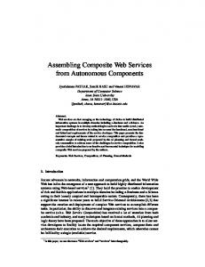
Figure 1: Class diagram generation from WSDL 2.0 tified and the method is applied on an example.
3.
UML-S: UML FOR SERVICES
UML-S (UML for Services) is an extension to UML 2.0 that allows for modeling Web services as well as their interactions. In UML-S, both class diagrams and activity diagrams are used to model and specify respectively Web services interfaces and their interactions. First, we provide a profile based on UML 2.0 class diagrams in section 3.1 and transformation rules from WSDL 2.0 to said diagram are provided in section 3.2. After that, a profile based on UML 2.0 activity modeling is given in section 3.3. Finally, transformation rules from UML-S to WS-BPEL 2.0 are introduced in section 3.4.
3.1 UML-S class diagram UML defines a class diagram as a static-structure which describes a software system. It models the system’s classes as well as their attributes and methods. The relationships between the classes are also represented. To model Web services interfaces, UML-S makes the analogy between a class and a Web service. To distinguish a Web service from an usual UML class, UML-S adds a ≪WebService≫ stereotype to classes corresponding to Web services.
3.2 WSDL 2.0 to UML-S class diagram Web Service Description Language (WSDL) is a XML based language, recommended by W3C, that provides a model to describe Web services. The WSDL description of a Web service presents its methods, its messages and complex types involved. It is worth noting that UML-S class diagrams can directly be generated from the Web services’ WSDL, as presented in figure 1. Indeed, a UML-S class diagram can be considered as a user-friendly mean for representing the Web services’ WSDLs. In this part, we provide the basic transformations rules to convert a WSDL 2.0 file into an UML-S class diagram. First
of all, the WSDL parser should locate the service section. It indicates the name of the service that will be used to name the WebService class, as well as the name of the interface (used to be called portType in WSDL 1.1). Once the interface’s name is known, the parser needs to find it in the WSDL file. The interface section allows to fill in part of the Webservice class’ methods. Indeed, it mentions the names of the methods provided by the Web service using operation tags. The parser is also able to retrieve from the operation sections the names of the methods’ input/output messages. Once the names of the input / output messages are retrieved, the parser can find their definition in the types section of the WSDL. Indeed, since WSDL 2.0, messages are defined using XML schema in the types section, with the other complex types, instead of using separate message sections. Messages are defined using an element tag, from which, the parser is able to retrieve the names of the parameters (or output if it is an output message) as well as their type (complex or not). At this stage, it is possible to generate the whole WebService class. The only missing things are the classes corresponding to the complex types handled by the Web service and the association links between the Web service and the said classes. In element tags, simple types are prefixed with xsd namespace. The ones using a different namespace are complex types. They should be represented as classes in the UML-S diagram (without any stereotype) and an association should be added between the WebService class and the complex type class. Complex types are also defined in the types section of the WSDL, using XML schema. From the XML definition of the complex type, it is possible to fill in the content of the UML-S class, that is to say its properties (names and types). At this point, the parser is thus able to generate the whole class diagram corresponding the imported Web service’s WSDL. Converting a WSDL document into a class diagram is straightforward given the similarity of both models. However, UML-S class diagram is a lot more user-friendly than WSDL and allows for a better understanding of the Web service.
3.3 UML-S activity diagram Although the class diagram is very useful to help visualizing the Web services interfaces and the complex types involved, it lacks the dynamism implied by Web services interactions. Activity diagrams are particularly adapted to model business processes. A business process can be defined as a set of coordinated tasks, achieving a business goal. In the context of Web services composition, an activity models the internal behavior of a composite Web service’s method, and an action (i.e. step of an activity) corresponds to a call to another Web service, which induces interaction. UML activity diagram has built-in support for the five main flow control patterns mentioned by Aalst in [10] and supported by most composition languages, namely the sequence, parallel split, synchronization, exclusive choice and simple merge. Aalst also enumerates more advanced flow control patterns which are also supported by UML-S, using stereotypes to extend original UML. Web services are unreliable, therefore it can be interesting to contact several similar services
Figure 2: UML-S activity example and use only the first response received. The Discriminator, described by [5], allows to do so: it waits for one of the incoming parallel branches to complete before continuing and ”ignores” the others. The N-out-of-M Join pattern [3] is a generalization of the discriminator. Instead of waiting for one branch to complete, it waits for N branches and ignores the others. The Multi-choice will allow the execution of one or several branches in parallel, based on a decision. After a Multi-choice, one can use two different patterns to join the incoming branches: the Multiple merge or the Synchronizing merge that adds synchronization feature. An example of UML-S activity diagram is presented in figure 2. UML-S activity diagrams are presented more exhaustively in [4].
3.4 WS-BPEL 2.0 transformation rules As stated earlier in this paper, UML-S allows to develop composite Web services according to MDE principles. This implies that UML-S models can be converted into platform specific code using a given set of transformation rules. In this part, the necessary rules to generate WS-BPEL 2.0 code from UML-S diagrams are provided. Business Process Execution Language (WS-BPEL or BPEL for short) [1] is an execution language for business processes that is widely used and that was standardized by OASIS, making it a good candidate for UML-S code generation. In the following, WS-BPEL 2.0 transformation rules are provided for almost all of the flow control patterns supported by UML-S, that is to say sequence, parallel split, synchronization, exclusive Choice, simple merge, multi-choice, synchronizing merge, discriminator, N-out-of-M join, and while loop. Unfortunately, the remaining pattern (multiple merge) is unsupported in WS-BPEL 2.0 and we could not find a workaround for it. Indeed, the multiple merge cannot be achieved because BPEL is block structured and it is impossible for two threads of execution to run through the same path in the same process instance. Concerning the discriminator pattern (and its generalization, the N-out-of-M join), it cannot be achieved using links in the flow construct. Indeed, when joining incoming links, there is always a joinCondition (implicit OR joinCondition if not explicitly specified). The problem is that the joinCondition requires the status of all incoming links to be known prior evaluation, which induces an undesired synchronization. This limitation was mentioned by Wohed et al. in [11]. However, we managed to find a way around this limitation, using BPEL
fault mechanism as presented in figures 4 and 5. A sequence can be written in BPEL using the sequence activity or using links activities within a flow construct. Both the parallel split and the synchronization patterns can be expressed in BPEL with a flow activity within a sequence construct. Concerning the exclusive choice, it was permitted to express it in an easy manner in BPEL4WS 1.1, using a switch activity. However, The switch is no longer supported in WSBPEL 2.0. Therefore, it is now required to express it using the way inherited by WSFL, that is to say using links in a flow construct. The corresponding design choice is represented in figure 3. Note that the BPEL code is the same for an exclusive choice and a multi-choice. Indeed, it will be an exclusive choice provided that the conditions (C1 and C2 in figure 3) are disjoined, a multi-choice otherwise (because several execution branches can be chosen and executed in parallel).
$C1
$C2
Figure 3: Choice and Merge patterns In the code provided in figure 3, a flow is used within a sequence construct. As a consequence, it will act as a simple merge if the transition conditions are disjoined or as a synchronizing merge otherwise. In [11], Wohed et al. could not find a solution to express the discriminator pattern using BPEL, leaving the problem unsolved. In figure 4, we propose a suitable solution. As one can see, our proposal makes use of BPEL fault mechanism. Indeed, each of the parallel execution branches throws a fault (named ”F” in the example) once it is completed. A scope activity called discriminator was added to include the flow
activity. A fault handler is added in this scope to catch fault ”F”. In the catch activity, a simple empty activity is used, because faults are merely used here to get out the flow construct once one execution branch is completed. In the example, Activity D will be executed one time only, when one of the parallel execution branches was completed.
One of the objectives of the EU project called ASSET is the implementation of a platform of coordinated and distributed location-based services. UML-S was introduced as a first step towards fulfilling this particular goal. Further development issues will be addressed in the future and a fully functional UML-S framework is currently under development. Future work will also involve Max-plus algebra based analysis and evaluation.
5. ACKNOWLEDGMENTS This work is supported by the EU project ASSET (Advanced Safety and Driver Support for Essential Road Transport, 2008-2011).
6. REFERENCES Figure 4: Discriminator pattern
0 $completed + 1 $ c o m p l e t e d
$completed = N
$completed + 1 $ c o m p l e t e d $completed = N
Figure 5: N-out-of-M Join pattern In figure 5, the discriminator BPEL code was adapted in order to express its generalized pattern, the N-out-of-M Join. The proposed code makes use of an additional variable in order to store the number of branches that are already completed. Once this value reaches N (the number of branches that one is awaiting for), a fault is thrown in order to get out of the flow construct. With this code, synchronization is made with N branches out of M and the remaining branches are simply ignored.
4.
CONCLUSION
Building composite Web services remains a difficult task although it could be simplified through providing sufficient support for traditional workflow modeling. Thus, needs were identified and it was explained how UML class diagram and activity diagram could be extended to meet these needs. This paper introduced UML-S (UML for Services), an UML 2.0 extension consisting of an UML profile and guidelines develop composite Web services according to MDE principles. UML-S can be used in early stages of development, to help specify graphically Web services interfaces and their interactions. It is then possible to generate platformspecific code from these high-level UML-S models using the transformations rules provided in this paper.
[1] Business process execution language (bpel), oasis,. http://docs.oasis-open.org/wsbpel/2.0/wsbpelv2.0.html. [2] M. Bakhouya and J. Gaber. Service composition approaches for ubiquitous and pervasive computing environments: A survey. Agent Systems in Electronic Business, Ed. Eldon Li and Soe-Tsyr Yuan, IGI Global, (978-1-59904-588-7):323–350, 2007. [3] M. Dumas and A. H. ter Hofstede. Uml activity diagrams as a workflow specification language. *UML* 2001 — The Unified Modeling Language Modeling Languages Concepts and Tools, 2185:76, 2001. [4] C. Dumez, A. Nait-Sidi-Moh, J. Gaber, and M. Wack. Modeling and specification of web services composition using uml-s. The 4th International Conference on Next Generation Web Services (NWeSP’08), 2008. [5] R. Hamadi and B. Benatallah. A petri net-based model for web service composition. In ADC ’03: Proceedings of the 14th Australasian database conference, pages 191–200, 2003. [6] F. Leymann. Web services flow language (wsfl 1.0). http:// www4.ibm.com/software/solutions/webservices/pdf/WSFL.pdf, 2001. [7] A. Nait-Sidi-Moh, C. Dumez, J. Gaber, and M. Wack. Petri net based verification and validation of uml-s models. Submitted to the 23rd IEEE International Conference on Advanced Information Networking and Applications(AINA2009), 2008. [8] D. Skogan, R. Groenmo, and I. Solheim. Web service composition in uml. In Proceedings. Eighth IEEE International Enterprise Distributed Object Computing Conference, 2004. EDOC 2004., pages 47–57, 2004. [9] S. Thatte. Xlang: Web services for business process design, microsoft corporation. http://msdn.microsoft.com/enus/library/aa577463.aspx, 2001. [10] W. van der Aalst. Don’t go with the flow: Web services composition standards exposed. IEEE Intelligent Systems, 18:72–76, 2003. [11] P. Wohed, W. M. P. v. d. Aalst, M. Dumas, and A. H. M. t. Hofstede. Pattern based analysis of bpel4ws. QUT Technical report, FIT-TR-2002-04, Queensland University of Technology, Brisbane, 2002.