to Enterprise Computing, John Wiley and Sons, 2003. [10] P. V. Gorp, H. Stenten, ... [18] M. Paulk, "Extreme Programming from a CMM. Perspective," IEEE ...
Model Refactoring with an Aspect-Oriented Model Transformation Engine Jing Zhang, Yuehua Lin, Jeff Gray Department of Computer and Information Sciences University of Alabama at Birmingham Birmingham, Alabama, USA {zhangj, liny, gray} @ cis.uab.edu Abstract Refactoring is an essential approach toward improving the internal structure of a software system while preserving its external behavior. Traditional refactoring techniques have focused on the implementation stage, with source code as the primary artifact of the refactoring process. However, a recent trend is to apply the concepts of refactoring to higher levels of abstraction. Consequently, model refactoring is emerging as a desirable means to improve design models using behavior-preserving transformations. This paper provides an aspect-oriented approach toward implementing model-level refactoring. An aspect model weaver has been developed and provides a generalized underlying transformation engine for manipulating models. A model refactoring browser is integrated within the model weaver to enable the automation and customization of various refactoring methods for either generic models or domain-specific models. A result of this work is the capability to perform model refactoring rapidly.
1. Introduction Refactoring was first proposed by Opdyke [17] in 1992 as a methodology for restructuring programs. Over the past decade, refactoring has grown into a disciplined technique to improve the maintainability of software systems by changing its internal structure without altering its external behavioral properties. With proper tool support, refactoring can be an efficient and effective way to help improve the design of software, make software easier to understand, and to assist in identifying errors [7]. In addition, lightweight development methods, such as eXtreme Programming (XP) [18], has promoted refactoring as a core development practice.
However, traditional refactorings focus primarily on the code level, i.e. the implementation and maintenance phases during the software life-cycle, and neglect the earlier stages of design. It is well-known that errors made early in the design process, but discovered late, are much harder to fix than errors made and found early in the development process. Thus, a strong need exists for tools that enable designers to discover errors early in development, and to better modularize their models, not just their code [3]. Applying refactoring as early as possible during the software life-cycle can improve the quality of design and reduce the complexity and cost in the successive phases. According to a recent survey on software refactoring [15], several researchers have begun to investigate refactoring at the design level, specifically in terms of UML models. The concept of model refactoring is thus emerging as a desirable means to improve design models using behaviorpreserving transformations. Likewise, aspect-oriented software development (AOSD) [12] is maturing as a new paradigm to improve the modularity of software. Aspects aid a developer in properly separating concerns that crosscut the hierarchy of a software artifact and assist in evolutionary tasks in order to meet new requirements. From our experience, it is quite natural to apply aspects in support of model refactoring. The main contribution of this paper is to provide an aspect-oriented approach toward implementing modellevel refactoring. An aspect model weaver has been developed to provide a generalized underlying transformation engine for manipulating models. A model refactoring browser is integrated within the model weaver to enable the automation and customization of various refactoring methods for either generic models or domain-specific models. The paper is structured as follows. Section 2 gives an overview of the aspect model weaver engine. The
model refactoring browser is introduced in Section 3. In Sections 4 and 5, examples are presented to illustrate generic and domain-specific model refactorings. The paper concludes with a section on related and future work.
Specification Strategies and Aspects
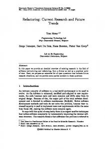
2. C-SAW: An aspect-oriented model transformation engine Model-Integrated Computing (MIC) [23] has been refined at Vanderbilt University over the past decade to assist with creation and synthesis of computer-based systems. As a variant of the Model-Driven Architecture (MDA) [9, 14], a key application area for MIC is those domains that tightly integrate the computational structure of a system and its physical configuration. In such systems, MIC has been shown to be a powerful tool for providing adaptability in frequently changing environments. A specific instance of the type of domain-specific modeling supported by MIC is implemented using the Generic Modeling Environment (GME) [13]. The GME is a UML-based meta-modeling environment that can be configured and adapted from meta-level specifications (called the modeling paradigm) that describe the domain. When using the GME, a modeling paradigm is loaded into the tool to define an environment containing all the modeling elements and valid relationships that can be constructed in a specific domain. Thus, the approach provides a metaenvironment for constructing system and software models using notations that are familiar to the modeler. The Constraint-Specification Aspect Weaver (CSAW) is a model transformation engine implemented as a plugin component for GME. C-SAW unites the ideas of aspect-oriented software development (AOSD) with MIC to provide better modularization of model properties that are crosscutting throughout multiple layers of a model [11]. C-SAW offers the ability to explore numerous modeling scenarios by considering crosscutting modeling concerns as aspects that can be rapidly inserted and removed from a model. This permits a modeler to make changes more easily to the base model without manually visiting multiple locations in the model. Until C-SAW, these transformations and translations have largely been performed manually in practice. Additional information about C-SAW, including software downloads and video demos, is available at: http://www.gray-area.org/Research/C-SAW. The C-SAW model transformation engine is depicted in Figure 1. In this figure, a base model serves as input to the model weaver, and the output of the weaver is a new model that has a crosscutting concern
Input Models
Output Models
Figure 1. C-SAW overview dispersed across the original base. To perform this process, a specification aspect describes the binding and parameterization of strategies to specific entities in a model. A strategy is used to specify elements of computation and the application of specific properties to the model entities. The specification aspects and strategies are based on a special underlying language, called the Embedded Constraint Language (ECL) [11]. The ECL is an extension of OCL [25], and provides many of the common features of OCL, such as arithmetic operators, logical operators, and numerous operators on collections (e.g., size, forAll, exists, select). ECL also provides special operators to support model aggregates (e.g., models, atoms, attributes), connections (e.g., connpoint, target, refs) and transformations (e.g., addModel, setAttribute, removeNode) that provide access to modeling concepts that are within the GME. ECL is distinct from OCL with respect to sideeffects and model manipulation features. OCL is a declarative language and therefore it cannot support operations to create, update or remove the entities within a model, whereas the use of ECL requires the capability to introduce side-effects into the underlying model. This is needed because the strategies often specify transformations that must be performed on the model. This requires the ability to make modifications to the model as the strategy is applied. Therefore, ECL supports an imperative transformation [4] procedural style with numerous operations that can alter the state of the model. The application of ECL to model refactoring will be presented later in Sections 4 and 5.
3. Model refactoring browser C-SAW was originally developed for general cases of model transformation. In this paper, it is specifically applied to a special case of model transformation, i.e., model refactoring. In particular, the ECL is used to specify and implement the model refactoring process.
The following definition of model refactoring is adapted from Robert’s initial program refactoring definition [21]: Definition- A Model refactoring is a pair R = (pre; T) where pre is the precondition that the model must satisfy, and T is the model transformation. Within this definition, several trivial properties are also implied, such as the name and parameters of the refactoring. In the following sections, detailed explanations will be presented regarding the way CSAW passes the parameters to strategies and how the strategies are used to specify the precondition and transformations. An experimental model refactoring browser (see Figure 2) has been implemented as a plugin within GME. This plugin operates with the underlying CSAW transformation engine. The overall aim of this refactoring browser is to provide an interactive and automated framework for refactoring models. The model refactoring browser provides automation of generic pre-defined refactoring methods within the GME meta-model domain. It also enables the specification of user-defined refactoring strategies, either in the generic model or in any domain-specific model. For pre-defined refactorings, users select a subset of the models to be refactored, and provide the appropriate parameters to the specified refactoring method. During the automated refactoring of a model, any error messages will show up as soon as any
Figure 2. Model refactoring browser in GME
violation occurs. For user-defined refactorings, users specify their own refactoring strategies using ECL. Such customized refactorings will be stored in the browser for later reuse.
4. Generic model refactorings Generic modeling, i.e., meta-modeling, is the mapping of specification concepts onto entities, relations and attributes. The GME meta-modeling language is based upon UML class diagrams and integrated with OCL constraints. Therefore, the GME meta-models can be regarded as class diagrams in order to perform UML class diagram refactorings [22]. In addition, GME meta-models extend the notations of UML to support various generic modeling concepts, which give rise to analysis on GME meta-specific refactorings.
4.1. Class diagram refactorings UML class diagrams are widely adopted to help design and visualize software structure [6]. It is apparent that some refactorings introduced for code representation can also be applied to class diagrams. Furthermore, it may be more intuitive for the system developer or maintainer to discover the refactoring hot spots in the class diagram rather than the source code. Likewise, after a particular refactoring has been carried out, the impact of it may be better overviewed in a graphical notation. GME meta-models do not exactly follow the UML class diagram concepts; for instance, they do not provide “methods,” per se [1]. However, we can treat “methods” as part of class “attributes.” Thus, all of the method-related UML refactorings can be classified into attribute-related refactorings. Some of the code-level refactorings cannot be adapted to class diagram refactorings, e.g. “Extract Method.” Such cases are out of the scope of this paper. Fowler’s catalogue lists seventy-two object-oriented refactorings [7], among which we select “Extract Superclass” as a specific example for describing the application of ECL transformation strategies to refactor class diagrams. The “Extract Superclass” refactoring is defined as, “when you have two classes with similar features, create a superclass and move the common features to the superclass” [7] (see Figure 3). This refactoring helps to reduce the duplicate common features spread throughout different classes. Generally, a refactoring is composed of a name, several parameters, preconditions, and a sequence of strategies, all of which are specified below.
Name: Extract Superclass Parameters: selectedClasses, className Preconditions: 1. The className for the new super class must be unique, i.e., no other classes have the same name. 2. All of the selected classes must have at least one common attribute. Strategies: 1. Create a new superclass named as className. 2. Insert the common attributes into this superclass. 3. Delete the common attributes in each selected class. 4. Make an inheritance relationship from the superclass to the selected classes.
attributes are found in the current modeling scope, the second strategy “extractSuper” will begin to execute. As a result of this refactoring, a new superclass will be introduced with extracted common attributes in the selected classes. This ECL code fragment can be applied to any number of classes within a specific scope of a model. defines start, evalPrecondition, extractSuper; strategy evalPrecondition (classes : modelList; className : string ) { Assert ( currentFolder().select(m | m.name() == className) -> size() == 0 ); declare commonAttrs : attributeList; commonAttrs := findCommonAttributes(classes); If (commonAttrs.size() > 0) then
extractSuper (classes, commonAttrs, className); endif; } strategy extractSuper (classes : modelList; commonAttrs : attributeList; className : string) { declare super : model; super := createModel("SuperClass", className); super.addAttributes(commonAttrs); classes->removeAttributes(commonAttrs); super.connectedTo("Inheritance", classes);
Figure 3. Extract Superclass refactoring Figure 4 contains the complete ECL specification of the “Extract Superclass” refactoring. An aspect is the starting point of a transformation process. It takes parameters that are provided by users (obtained from the refactoring browser) and passes them to strategies. A strategy can be called either within an aspect or by other strategies. Various standard functions are provided to enable easy and convenient manipulation of the GME models (e.g., createModel, addAttributes). For this particular refactoring, the precondition evaluation is specified as the first strategy to be executed. At the beginning, it uses an “Assert” statement to verify whether a class named “className” already exists in the current model folder. If the assertion fails, an error message will be displayed to indicate the violation of the above precondition, and the refactoring process will be terminated. On the other hand, if “className” does not yet exist, refactoring will continue to check if there are any common attributes within the selected classes. If common
} aspect start (selectedClasses : modelList; className : string) { evalPrecondition(selectedClasses, className); }
Figure 4. ECL for “Extract Superclass” Various kinds of ECL specifications for a wide range of class diagram refactoring methods have already been integrated into the model refactoring browser. A partial list of the implemented refactorings contains: Add Class, Extract Superclass, Extract Class, Remove Class, Move Class, Rename Class, Collapse Hierarchy, Add Attribute, Remove Attribute, Rename Attribute, Pull Up Attribute, and Push Down Attribute. These generic refactorings are pre-defined within the refactoring browser and can be used for any GME meta-model. A user of the refactoring browser may invoke these pre-defined refactorings by selecting the
name of the refactoring from a menu and providing the required parameters. The refactoring process will be performed automatically. Users of the refactoring browser are allowed to customize a pre-defined refactoring by modifying the corresponding ECL code in the refactoring browser.
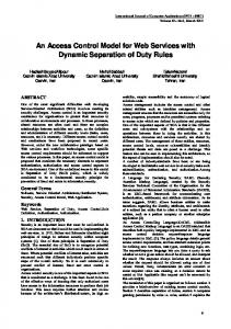
4.2. GME meta-model refactorings This section presents several GME meta-specific refactorings. The GME meta-model extends the concepts of UML entities and relationships to support a set of generic modeling notations, such as model, atom, connection, set, and reference [1]. Figure 5 illustrates a simple meta-model that represents a system administration domain. This meta-model contains entities acting as the major roles in the domain, such as Administrator, PC, and Server, as well as the Administrate relationship between these entities. In this domain, an Administrator is responsible for a set of PCs and Servers. A Server or PC may be controlled by several Administrators.
sets should be regarded as an alternate association technique that supplies greater convenience in many situations. The refactored meta-model that is based on a Set is shown in Figure 6. This refactoring process includes removing all of the “Administrator” connections from each device (PC and Server), replacing the “Administrator” model by a Set, and connecting each device to the new Set through a “SetMembership” association.
Figure 6. Refactoring the meta-model using Set 4.2.2. Introduce FCO. Another kind of refactoring can be implemented on this meta-model by introducing a First Class Object (FCO), which is a generic concept representing a general class for all of the entities and relations in GME. The purpose of using a FCO is to enable objects that are inherently different (such as model, atom, reference, connection) to inherit from a common base class. Figure 7 illustrates the refactored meta-model for the system administration domain by inserting an FCO. In this case, a generic entity that represents anything that a system administrator can govern is specified by the FCO named “Network.” All of the devices inherit from this FCO. Consequently, in such a case only one connection is needed to link the “Administrator” model to the “Network” FCO.
Figure 5. A system administration meta-model The meta-model is rather simple. Nevertheless, it requires every system device managed by an administrator to have an “Administrate” connection. The drawback is that one-hundred devices would require one-hundred connections. Even if a new visualization was assigned to the connection lines, the vast number of associations would render the diagram unreadable. This suggests the need for a “multiconnections” refactoring. The following subsections describe two refactoring methods that use different entity concepts from the GME meta-model. 4.2.1. Replace connections with Set. The first refactoring utilizes the idea of “Set,” which is the GME concept recommended for situations in which an object has to be associated with a relatively large number of neighboring objects in a diagram. The members of Set are “owned” by the Set through the “SetMembership” connection defined in the GME. The concept of Sets is not as indispensable as that of connections because they can usually be replaced by connections. However,
Figure 7. Refactoring the meta-model using FCO Because of the rich set of concepts in the GME meta-model, there exist other feasible methods for GME meta-specific refactorings, such as Introduce Reference, Compose Atoms into Model, and Replace General Inheritance with Implementation/Interface Inheritance. These refactorings can be specified easily using ECL and integrated into the model refactoring browser.
5. Case Studies: Domain-specific model refactorings Due to the intrinsic generic modeling features of GME, the C-SAW model transformation engine can be applied to any level of model transformation, not only to the generic GME meta-model. This section provides two examples within two different modeling domains to demonstrate refactoring of domain-specific models.
5.1. Refactoring AQML models The Adaptive Quality Modeling Language (AQML) [16] is a domain-specific graphical modeling language developed for modeling Distributed Real-Time Embedded (DRE) systems with quality-of-service (QoS) adaptation configurations. The key focus of this approach is to raise the level of abstraction in specifying QoS policies by providing a control-centric design for the representation and analysis of the adaptation software. Within the QoS Adaptation Modeling category, the designer can specify numerous details, such as: the different state configurations of the QoS properties, the legal transitions between the different state configurations, the conditions that enable these transitions, the data variables that receive and update QoS information, and the events that trigger the transitions. These properties are modeled using an extended Finite-State Machine (FSM) formalism. Figure 8 shows a QoS adaptation model of a video streaming scenario in the AQML. The application of QoS adaptation is used to minimize the latency on the video transmission. Cutting frame size is one of the feasible strategies to reduce the transmission rate to compensate for the increased load. There are six different states that are possible in Figure 8. After initialization, the camera is tracking over a specific area and transmitting the video. The video is initially transferred at the full frame rate with 100% full frame size (in “Nominal” state). As load increases on the communication resources, each image frame has to be cropped to 90% (see “Crop_90pc” state) or even 80% (see “Crop_80pc” state) of the original size. In fact, these three states perform the same task, i.e. adjust the frame size. In order to improve comprehensibility and modularity, we can apply the model refactoring technique to group related states together into a composite state by specifying ECL model transformation strategies. Because the AQML model is based on state machines, the generic analysis regarding state diagram refactoring is provided below. This refactoring algorithm is composed of a name, a
Figure 8. AQML model before refactoring couple of parameters, preconditions, and strategies. The selected objects are those states that users are willing to group, as well as their internal transitions. The new state name is for the composite state. These parameters are provided by the user of the refactoring browser. Name: Compose states into a composite state Parameter: selectedObjects, newStateName Preconditions: 1. This newStateName must be legitimate, i.e., no other state has the same name. 2. Find out all of the external states from which the selected states have the incoming transitions, in the name of “ExternalIncomingStateList.” Each found state in this list must have the identical set of transitions (“ExternalIncomingTransitionList”) leading to the identical set of selected states (“InternalSourceList”). 3. Find out all of the interior states in the selected set outward connecting to the external states, named “InternalDestinationList.” Each found state in such a list must have the identical set of transitions (“ExternalOutgoingTransitionList”) leading to the identical set of external states (“ExternalOutgoingStateList”). Strategies: 1. Create a new state model, under the name of newStateName. 2. Move all of the user-selected states along with all of the internal transitions into this new composite state. According to the GME metamodel definition, a connection is just an attachment to a first-class object (i.e. model, atom, etc.); whenever the objects are copied, moved or removed, those connections will lose one of their ends automatically. Consequently, all of the transitions in “ExternalIncomingTransitionList” as well as “ExternalOutgoingTransitionList” will be removed.
3.
Within this new state, insert an “Init” state and connect it to all of the states in “InternalSourceList.” 4. Within the composite state, insert an “End” state and make a transition from each state in “InternalDestinationList” to the end. 5. Go back to the outer model, and make a transition from each state in the “ExternalIncomingStateList” to the new composite state that will also be connected to each state in the “ExternalOutgoingStateList.” In this case, after the user makes a choice on a couple of specific states such as “Nominal”, “Crop_90pc” and “Crop_80pc” and provides the new composite state name “AdjustingFrameSize,” the model refactoring browser will begin to analyze the precondition. Because there exist only one “ExternalIncoming” state (“Initilization”) and only one “InternalSource” state (“Nominal”), precondition 2 is satisfied. All of the three selected states are in the “InternalDestinationList” and identically connect to one “ExternalOutgoing” state (“Transmission”); thus, it meets precondition 3. During the transformation procedure, the “AdjustingFrameSize” state will be created first, within which the three selected states plus their internal transitions will be moved. A new “Init” state leads to “Nominal” and a new “End” state leaves from all three states. Finally, transitions are introduced to connect “Tracking” and “Transmission” states by means of the new composite state. Figure 9 shows the refactored AQML model as a result. The upper model delineates the new state
Figure 9. AQML model after refactoring
diagram with a composite state “AdjustingFrameSize” and the bottom model illustrates the three sub-states contained by this composite state. Due to the limited space, the corresponding ECL strategies are omitted here.
5.2. Refactoring Petri Nets Petri Nets (PNs) [19] are well-known as a basic model for the general theory of concurrency, and as a formal specification technique for distributed and concurrent systems. Petri Nets have obtained extensive usage and acceptance due to their easy-to-understand visual notation and a wide range of available tools. A Petri Net is primarily characterized by places, transitions and arcs and is graphically represented by a directed bipartite graph in which places are drawn as circles, transitions are drawn as bars, input and output arcs (from a place to a transition or a transition to a place) are drawn as arrows. The execution of a Petri Net is controlled by the position and movement of markers (tokens). It incorporates the notion of a distributed state, called the marking, which is graphically represented by black dots (tokens) in places. The dynamic behavior of a Petri Net is governed by transition firing rules. A transition can fire if all of its input places contain at least one token, and if all of its inhibitor places do not contain tokens. If these conditions are satisfied, the transition is said to be enabled, and its firing removes one token from all its input places and generates one token in each of its output places (assuming the weight of each arc is 1). Figure 10 shows a Petri Net model describing a simplified version of the classic Dining Philosophers problem. This problem consists of philosophers sitting at a table who do nothing but think and eat. The philosophers each have a chopstick next to them, both of which they need in order to eat. The initial marking for this model will have all philosophers in the “Thinking” state, and all of the chopsticks available. Because there is only a finite set of chopsticks, it is not possible for all philosophers to eat at the same time. The Petri Net shown here models a philosopher that takes both chopsticks simultaneously, thus preventing the situation where some philosophers have one chopstick, but are not able to pick up the second one. This Dining Philosophers Petri Net model is deadlock-free, i.e. there always exists at least one philosopher whose state is able to transfer from “Thinking” to “Eating.” Nevertheless, partial starvation is still possible because the firing of one transition named “Hungry” prevents the other neighboring transition from firing. If one philosopher rapidly alternates between “Thinking” and “Eating,” then the neighboring philosophers may never obtain the
Figure 10. Dining Philosophers Petri Net “Chopstick” that they need, which will result in starvation. In such a case, the “Chopstick” place models a semaphore to guarantee only one of the two adjacent philosophers can eat at the same time. One possible solution to avoid starvation is to refactor the Petri Net model to enforce that every transition must be fired in alternating turns. A potential algorithm can be specified as follows: 1. Pick out the semaphores from among the places in the model. 2. For each semaphore and its two output transitions, insert two new places, one with a marker and the other without a marker. Connect the two new transitions to the existing model to form a cycle (see highlights in Figure 11). To verify that the refactored Dining Philosophers Petri Net is starvation-free after applying this algorithm, we might keep track of the control flow among the transitions one by one. Figure 11 illustrates this Petri Net model after refactoring. Due to the six added places, initially only the philosopher on the left can be triggered from the “Thinking” state to “Eating” state. This transition will move the markers in P1 and P2 to Q1 and Q2. After the first philosopher finishes eating and places the chopsticks back on the table (marker goes from “Eating” to “Chopsticks”), the philosopher
in the middle will be enabled to eat. Likewise, the philosopher on the right will eventually start to eat in turn. Therefore, all of the philosophers will obtain the opportunity to eat in turn. The corresponding ECL code fragment for implementing this particular refactoring procedure is illustrated in Figure 12. An iteration over the selected list of the Petri Net places checks to see if they meet the precondition of being semaphores, and then inserts two new places with appropriate connections. This strategy is suitable for any number of semaphores involved in the refactoring. For simplicity, it is assumed that one semaphore only controls two transitions and it is the user’s responsibility to select the proper semaphores. With ECL, users can express their objectives in a more concise manner than using traditional program languages. It also permits a modeler to make changes flexible to the base model without manually visiting multiple locations in the model (for instance, imagine such a case when there are 100 semaphores within one Petri Net model). Thus, the C-SAW model transformation engine and its associated language ECL permit the modeler to make statements of quantification across the model in an aspect-oriented style that supports improved scalability.
Figure 11. Free-starvation Dining Philosophers Petri Net defines freeStarvation, refactoringPetriNet;
6. Related work
strategy freeStarvation() { declare dstList: modelList; dstList := findOutConnections(); Assert(dstList.size() = = 2); declare dst1, dst2, p, q: model; declare static num: integer; dst1 := dstList.get(0); dst2 := dstList.get(1); p := createModel("InitMarker","P"+intToStr (num)); q := createModel("Place", "Q" + intToStr (num)); num := num + 1; addConnection(dst1,p); addConnection(p, dst2); addConnection(dst2,q); addConnection(q, dst1); } aspect refactoringPetriNet (selectedObjs : objectList) { selectedObjs->freeStarvation(); }
Figure 12. ECL for free-starvation in Petri Net
There are several ongoing investigations into the topic of model refactoring. This section briefly acknowledges some of the work that has been done in this area. Sunyé et al. [22] proposed an initial set of refactorings for UML class diagrams and statecharts. Astels [2] presented techniques for detecting bad smells in UML. Boger [5] implemented a refactoring browser for UML to automate the process of predefined refactoring methods. Porres [20] applied rule-based update transformations to model refactorings. In addition, several researchers are concentrating on a design pattern based model refactorings [2, 8]. Gorp [10] extends the UML metamodel for automating the consistency between the model and the code. Tichelaar [24] developed a specific meta-model to support language-independent refactorings for Smalltalk and Java. Several of the approaches cited above provide theoretical investigations that do not have concrete implementations of representative tools. Some of the implementation tools provide the automation of preexisting refactorings, but do not offer the extensibility of user-defined refactorings. Some tools can not
support refactoring automation. In contrast, our model refactoring browser is built on top of an underlying model transformation engine that can enable the automation and customization of refactorings for either generic meta-models or domain-specific models.
7. Conclusions and Future work This paper described an approach to model refactoring that is based on C-SAW - an existing aspect-oriented model transformation engine. An initial prototype model refactoring browser tool serves as a front-end to C-SAW and exists as a plugin within the GME. A set of predefined refactorings are integrated within the browser in order to facilitate automated refactorings. Furthermore, the ECL can be used to specify new refactoring strategies. This interactive tool permits users to request refactorings to either a GME meta-model, or a domain-specific model (e.g., Petri Nets, or finite state machines). With respect to future work, there are several extensions that will be integrated into the model refactoring browser. Behavior preservation is an important issue with regard to model refactoring. To preserve the semantics of a model, it is necessary to measure the impact of a model transformation in such a way that it can be proved that the behavior of the model is unchanged. In the GME, the meta-model is specified with UML and OCL constraints. The metamodel can assist in the determination of behavior preservation [22]. However, a more precise formalism is required for semantic and behavior analysis to ensure the preservation of the model behavior. Because the behavior of different models may have different specification, and various aspects of the behavior may depend on various user-specific concerns [15], it’s essential to allow the modelers to provide the information of the behavior property that will remain invariant during a model refactoring. We are in the process of developing a model testing suite to assess behavior preservation by executing user-specified test cases on target and refactored models. In addition, a debugging toolkit is planned for C-SAW. This will be indispensable for detecting errors in the ECL specification during the refactoring execution process.
8. Acknowledgements This project is supported by the DARPA Program Composition for Embedded Systems (PCES) program.
9. References [1] The Generic Modeling Environment: GME 4 User’s Manual, Institute for Software Integrated Systems, Vanderbilt University, 2004. [2] D. Astels, "Refactoring with UML," In Proceedings of 3rd International Conference on eXtreme Programming and Flexible Processes in Software Engineering (XP2002), Alghero, Sardinia, Italy, May 2002, pp. 67-70. [3] I. D. Baxter, C. Pidgeon, and M. Mehlich, "DMS: Program Transformations for Practical Scalable Software Evolution," 26th International Conference on Software Engineering, Scotland, UK, May 2004. [4] J. Bézivin, N. Farcet, J.-M. Jézéquel, B. Langlois, and D. Pollet, "Reflective Model Driven Engineering," In Proceedings of UML 2003 Conference, Springer-Verlag LNCS 2863, San Francisco, CA 2003, pp. 175-189. [5] M. Boger, T. Sturm, and P. Fragemann, "Refactoring Browser for UML," Objects, Components, Architectures, Services, and Applications for a NetworkedWorld: International Conference NetObjectDays, NODe 2002, Springer-Verlag LNCS 2591/2003, Erfurt, Germany, October 2002, pp. 366-377. [6] D. F. D'Souza and A. C. Wills, Objects, Components, and Frameworks with UML : The Catalysis(SM) Approach, Addison-Wesley, 1998. [7] M. Fowler, K. Beck, J. Brant, W. Opdyke, and D. Roberts, Refactoring: Improving the Design of Existing Code, Addison-Wesley, 1999. [8] R. France, S. Ghosh, E. Song, and D.-K. Kim, "A Metamodeling Approach to Pattern-Based Model Refactoring," IEEE Software, September 2003, pp. 52-58. [9] D. S. Frankel, Model Driven Architecture: Applying MDA to Enterprise Computing, John Wiley and Sons, 2003. [10] P. V. Gorp, H. Stenten, T. Mens, and S. Demeyer, "Towards automating source-consistent UML Refactorings," In Proceedings of UML 2003 Conference, Springer-Verlag LNCS 2863, San Francisco, CA, October 2003, pp. 144-158. [11] J. Gray, T. Bapty, S. Neema, and J. Tuck, "Handling Crosscutting Concerns in Domain-Specific Modeling," Communications of the ACM, October 2001, pp. 87-93. [12] G. Kiczales, E. Hilsdale, J. Hugunin, M. Kersten, J. Palm, and W. Griswold, "Getting Started with AspectJ," Communications of the ACM, October 2001, pp. 59-65. [13] Á. Lédeczi, A. Bakay, M. Maroti, P. Volgyesi, G. Nordstrom, J. Sprinkle, and G. Karsai, "Composing DomainSpecific Design Environments," IEEE Computer, November 2001, pp. 44-51. [14] S. J. Mellor, S. Kendall, A. Uhl, and D. Weise, MDA Distilled, Addison-Wesley, 2004. [15] T. Mens and T. Tourwé, "A Survey of Software Refactoring," IEEE Transactions on Software Engineering, February 2004, pp. 126-139. [16] S. Neema, T. Bapty, J. Gray, and A. Gokhale, "Generators for Synthesis of QoS Adaptation in Distributed Real-Time Embedded Systems," First ACM SIGPLAN/SIGSOFT Conference on Generative Programming and Component Engineering (GPCE '02), Springer-Verlag LNCS 2487, Pittsburgh, PA, October 2002, pp. 236-251.
[17] W. F. Opdyke, "Refactoring: A Program Restructuring Aid in Designing Object-Oriented Application Frameworks," PhD Thesis, University of Illinois at Urbana-Champaign, 1992. [18] M. Paulk, "Extreme Programming from a CMM Perspective," IEEE Software, Nov/Dec 2001, pp. 19-26. [19] J. L. Peterson, "Petri Nets," ACM Computing Surveys, September 1977, pp. 223-252. [20] I. Porres, "Model Refactorings as Rule-Based Update Transformations," In Proceedings of UML 2003 Conference, Springer-Verlag LNCS 2863, San Francisco, CA, October 2003, pp. 159-174. [21] D. B. Roberts, "Practical Analysis for Refactoring," PhD Thesis, University of Illinois at Urbana-Champaign, 1999. [22] G. Sunyé, D. Pollet, Y. L. Traon, and J.-M. Jézéquel, "Refactoring UML Models," In Proceedings of UML 2001
Conference, Springer-Verlag LNCS 2185, Toronto, Canada, October 2001, pp. 138-148. [23] J. Sztipanovits, "Generative Programming for Embedded Systems," Keynote Address: Generative Programming and Component Engineering (GPCE), Springer-Verlag LNCS 2487, Pittsburgh, Pennsylvania, October 2002, pp. 32-49. [24] S. Tichelaar, S. Ducasse, S. Demeyer, and O. Nierstrasz, "A Meta-model for Language-Independent Refactoring," In Proceedings of International Symposium on Principles of Software Evolution (ISPSE 2000), IEEE Computer Society Press, Kanazawa, JAPAN, November 2000, pp. 157-169. [25] J. Warmer and A. Kleppe, The Object Constraint Language: Getting Your Models Ready for MDA, AddisonWesley, 2004.