Model Transformation and Synchronization Process ...
Recommend Documents
languages provide general solutions but do not support issues specific to a distinct ... generic solutions for model transformation problems distinct to the area of ...
additionally emphasizes the delicacy of business process transformation.
Concerning the .... The Model consists of 8 steps: (1) understanding the context; (
2) ...
Lectures on distributed systems. Process Synchronization and Election
Algorithms. Paul Krzyzanowski. Process Synchronization: mutual exclusion.
Process ...
6.2. Silberschatz, Galvin and Gagne 2009. Operating System Concepts – 8th
Edition. Module 6: Process Synchronization. Background. The Critical-Section ...
How do we go about acquiring locks to protect regions of memory? • How is
synchronization really used? OPERATING SYSTEM. Synchronization ...
ABSTRACT. Development of Web software is still an inefficient and error- prone process. We need integrated techniques and tool support for automated ...
oped method is applied to construct an atlas of diffusion weighted images for a set ... local deformation given by the mapping from subject to atlas space [4,5,6].
and Training Authority (TETA), South African Airways, Eskom and the South. African Broadcasting Authority, therefore confirming that poor corporate governance ...
programmers and shared memory which specifies how the memory operations of a ... and Technology, Mandi Gobindgarh (Punjab), India . B. Sequential ...
Standard and modern theoretical reasoning in economics and political economy ... This paper was presented at the Seventh World Congress of Social Economics in ..... of âmodern macro-economicsâ; e.g. Blanchard and Fischer, 1989; Wagner, ..... des
Mar 9, 2014 - on a one-dimensional periodic lattice on the sites of which the ... biological systems over length and time scales that span several orders of magnitude. ... the external torques, the resulting model is the so-called Brownian ...... m's
Mar 9, 2014 - the external torques, the resulting model is the so-called Brownian mean-field (BMF) model. [24,25], introduced as a generalization of the ...
Feb 28, 2008 - Jia Zeng,â MuDi Xin,â KunWei Li,â Hao Wang,*,â Hui Yan,â and WenJun Zhangâ¡. The College of Materials Science and Engineering, Beijing ...
The hotel industry is experiencing heightened competition that has brought a ...
Lack of customer service standardization across the Hotel's company portfolio.
Middle Ages learnt their art from the Arabs in Spain and Southern Italy, who in ... "
dead, leaden state of mind," to that of realising its own light nature and that is ...
focused recently. Model transformation problems can be formulated as graph ..... graph transformation engine can also be used by a Java API and thus, can be.
Model transformation problems can be formulated as graph transformation .... system GT S = (T,R) consisting of a type graph T and a set of transformation rules R. The abstract syntax graphs of the source models can be specified by that subset ...
THE APPLICATION OF THE LAND TRANSFORMATION, GROUNDWATER FLOW ... 2000a, Pijanowski et al., 2000b) couples Artificial Neural Network (ANN) ...
presents an approach for measuring business model adaptation. With regard to ... The conceptual framework for adaptive business models by Di Valentin et al.
Feb 25, 2004 - et al., 1998) with correspondence assertions (Gordon & Jeffrey, 2001a, ... While (Gordon & Jeffrey, 2001b) ...... Gordon, Andrew, & Jeffrey, Alan.
based on this model (2) define a subscription based event / voting mechanism ...... tiable compliance rule graphs in Process-Aware information systems,â in Proc.
Sep 19, 2005 - Model composition and model transformations that incorporate new ... by one or more source models; in a transformation, the new features are ...
Mar 30, 2010 - automatic model generation via constraint satisfaction using our tool Cartier for ... The mutation scores show that input domain partitioning strategies guide ... Model generation for black-box testing involves finding valid input ...
Model Transformation and Synchronization Process ...
The complexity of embedded systems and software has grown significantly in .... Model-driven systems and software development as well as tool integration are ...
Model Transformation and Synchronization Process Patterns Georg MACHER, Graz University of Technology Christian KREINER, Graz University of Technology
Embedded systems are already integrated into our everyday life and play a central role in all domains including automotive, aerospace, healthcare or industry. The complexity of embedded systems and software has grown significantly in recent years. Software’s impact on embedded system’s functionality, has led to an enormous increase of SW complexity, while reduction of innovation cycles and growing demand for extra-functional requirements. Supporting cooperation between the involved domain and SW development experts to combine their expertise is a core challenge in embedded software development. Nevertheless, today, a lack of tool support and integration makes it impossible to cover the complete development life cycle using model-driven development (MDD) paradigms. This paper identifies patterns of concurrent workflows in embedded system development which can be used to identify dependencies and consequences of concurrency of workflows and thus, highlight the basic problem and provide know-how how to overcome these issues and foster MDD along the development life cycle. Categories and Subject Descriptors: H.5.0 [Information Interfaces and Presentation]: General—; H.1.1 [Models and Principles]: System and Information Theory—; K.2.2 [Computers and Society]: Social Issues—
General Terms: Model Transformation and Synchronization Additional Key Words and Phrases: embedded systems, model-driven development, concurrent work ow pattern. ACM Reference Format: Macher G. and Kreiner C., 2015. Model Transformation and Synchronization Process Patterns. jn 0, 0, Article 0 ( 0), 11 pages.
1.
INTRODUCTION
Embedded systems are already integrated into our everyday life and play a central role in all domains including automotive, aerospace, healthcare or industry. In 2010, the embedded systems market accounted for almost 852 billion dollar, and is expected to reach 1.5 trillion by 2015 (assuming an annual growth rate of 12%) [Petrissans et al. 2012]. As an example, in the automotive industry, embedded systems components are responsible for 25% of vehicle costs, while the added value from electronics components range between 40% for traditional vehicle up to 75% for electrics and hybrid vehicles [Scuro 2012]. Current premium cars imply more than 70 electronic control units (ECU) with close to 1 Gigabyte software code [Ebert and Jones 2009] implemented. This trend is also strongly supported by the ongoing replacement of traditional mechanical systems with modern embedded systems. This enables the deployment of more advanced control strategies, providing added values for the customer and more environment friendly vehicles. At the same time, automotive multi-core computing platforms enable the deployment of more advanced control strategies and a higher degree of integration, which leads to cost savings by reducing the number of ECUs. On the contrary, the higher degree of integration and the safety-criticality Permission to make digital or hard copies of all or part of this work for personal or classroom use is granted without fee provided that copies are not made or distributed for profit or commercial advantage and that copies bear this notice and the full citation on the first page. Copyrights for components of this work owned by others than ACM must be honored. Abstracting with credit is permitted. To copy otherwise, or republish, to post on servers or to redistribute to lists, requires prior specific permission and/or a fee. Request permissions from [email protected]. EuroPloP ’XX, July xx - xx, 20xx, Irsee, Germany Copyright is held by the owner/author(s). Publication rights licensed to ACM. ACM xxx-x-xxxx-xxxx-x ...$xx.00. http://dx.doi.org/xx.xxxx/xxxxxxx.xxxxxxx
of the control application increases the system’s complexity and raises new challenges. Safety standards such as ISO 26262 [ISO - International Organization for Standardization 2011] for road vehicles have been established to provide guidance during the development of safety-critical systems. They provide a well-defined safety lifecycle based on hazard identification and mitigation, and they define a long list of work-products to be generated. The key challenge in this context is to provide evidence of consistency during product development among the different work-products. Model-driven development (MDD) is alleviating the issue of inherent complexity and the most promising approach of interdisciplinary development [Broy et al. 2008], but in case of embedded system development seamless cooperation between the involved domains and development experts is a core challenge. Today, a lack of tool support and integration makes it impossible to cover the complete development life cycle using MDD. During model-driven development of embedded systems frequently manifold model types of the same system under development exist spread over different stages of the development process and different development tools in use. In these cases special attention need to be paid to keep the dependent models consistent. Each model transformation implies potential sources for ambiguous mapping and often dependencies between the models are hard to identify. This paper identifies patterns of concurrent workflows in embedded system development which can be used to identify dependencies and consequences of parallel workflows. Thus, a highlighting of the basic problem and providing of know-how how to overcome these issues as well as encouragement of MDD along the development life cycle is done. In the course of this document, a description of the state of the art and related works is given in Section 2. The paper presents, according to our knowledge, three previously undocumented but common dependability patterns in concurrent embedded system development workflow F ORWARD U PDATE D EPENDENCY R ELATION (Section 4), B ACKWARD U PDATE D EPENDENCY R ELATION (Section 5) and B IDIRECTIONAL U PDATE D EPENDENCY R ELATION (Section 6). The intention of the three patterns presented in this work is to identify update dependencies between concurrent models and thereby set up the base for tool integration into a holistic tool-chain. The patterns do not need to be applied in a specific order, but are related to another. This is due to the fact that either one or the other shall be applied in case of concurrent development of dependent development models. In case of solely uni-directional dependability and independent workflows (e.g. generation of interim status model-based documentations), the F ORWARD U PDATE D EPENDENCY R ELATION pattern shall be applied. If feedback of information from one model to another is required after some refinement activity (e.g. updating of SW architecture model with SW function models), the B ACKWARD U PDATE D EPENDENCY R ELATION pattern shall be applied. Finally, the B IDIRECTIONAL U PDATE D EPENDENCY R ELATION pattern shall be used if a full concurrency development of mutually dependent models is required (e.g. concurrent SW and HW development). The patterns have been mined during the analysis of the actual model-driven development work-flow at our industrial partner. The aim of this analysis was the exploration of open issues and interface shortcomings of the MDD tools in place to setup a seamless model-driven development tool-chain covering all development phases. During this analysis the three types of relations between concurrent MDD models have been investigated. The identification of these relations serve the basis for a bridging of the ascetic MDD tools to a seamless tool-chain. 2.
RELATED WORK
Several existing approaches deal with model-driven development of embedded systems. Nevertheless, only a few number of publications focus on holistic tool-chains and methodologies. Still many system-wide and cross-domain constraints, such as dependability features (safety or security), need to be exchanged manually or without adequate methodical support across tool- and domain borders. Throughout our research we discovered several challenges. Model-driven systems and software development as well as tool integration are engineering domains and research topics aim at moving the development steps closer together and thus improving the consistency of the Model Transformation and Synchronization Process Patterns — Page 2
system over the expertise and domain boundaries. Although seamless solutions have not been achieved so far due to problems by using an inadequate tool-chain (e.g. redundancy, inconsistency and lack of automation) [Broy et al. 2008] or the usage of different specialized models for specific aspects at different development stages with varying abstraction levels [Holtmann et al. 2011]. Traceability between these different models is commonly established via manual linking due to a lack of automation and missing guidance. Two important gaps need to be bridged: First, missing links between system level tools and software development tools. Second, several very specific and non-interacting tools which require manual synchronization and therefore often rely on inconsistent, redundant information need to be aligned to one single source of information. Therefore, system design models have to be correctly transferred to the software engineering model, and later changes must be kept consistent [Giese et al. 2010]. A major drawback thereby stems from the bidirectional model transformation, each transformation step implies potential sources for ambiguous mapping and model mismatching. Recent projects which focus on model-driven development environments for automotive multi-core systems are the AMALTHEA Project1 , SAFE Project2 , and MAENAD Project3 . The work of Asplund et. al [Asplund et al. 2012] focus on tool integration in context of the automotive safety standard ISO 26262. The authors mention that tool integration is a complicated issue and guidance regarding tool integration into tool chains are very limited. Nevertheless, their work focuses more on tool qualification issues in ISO 26262 context and does not provide the mentioned guidance for tool integration. Finally, the work of Raschke et. al [Raschke et al. 2014] bases on the concept that development of systems is a sequence of evolutions, interrupted by revolutions. Therefore the authors build up a catalog of patterns for software modeling. This pattern catalog focuses on the dependencies between software models and software code and their possible relations. 3.
SPECIFICATION OF THE PATTERN
The following sections will discuss the patterns in more detailed manner. Therefore we specify the structure [Salingaros 2000; Alexander et al. 1977] in which we describe the three update-dependability patterns: —Context - Describes the situation in which the pattern can be applied and in which the problem occurs. —Problem - States the scenario which requires action to be taken and problems the pattern shall solve. —Forces - Gives additional motivation for usage of the pattern and describes the constraints which shape the specific solution for the problem. —Solution - Describes the steps and actions to be taken to solve the existing problem in the focus of the given context and specific forces. —Consequences - The application of the pattern solves the problem, but also results in some consequences, which themselves also include side effects. —Known Uses - publications which used the pattern —Example - Characterizes the context and problem scenario by a striking example.
Model Transformation and Synchronization Process Patterns — Page 3
3.1
Common Pattern Context
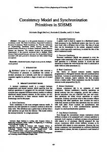
Common for all three patterns is an iterative model-driven development process of an embedded system. Figure 1 shows all phases of such a development life cycle with the involved tooling discontinuities. As can be seen in this figure, model-driven development iteratively updates the model over the time. This process lets developers produce partial implementations after each iteration. The figure highlights necessary tool transitions via the different colored backgrounds of the iteration steps and also indicates a potential pitfall of such an iterative model-driven development approach. Frequently manifold model types of the same system under development exist spread over different stages of the development process and different development tools in use. In case of such a concurrent development of dependent development models special attention need to be paid to keep the dependent models consistent. Each transformation step implies potential sources for ambiguous mapping and a common model as single source of information is rather unusual or too complex for application. For the course of this document this process is stretched over time, which leads to a corkscrew like representation.
Fig. 1. Iterative Model-Driven Development Process for Embedded Systems [Liggesmeyer and Trapp 2009]
Model Transformation and Synchronization Process Patterns — Page 4
4.
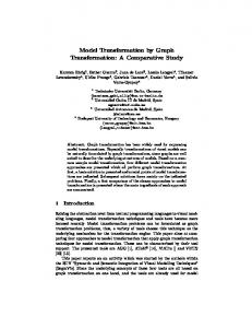
FORWARD UPDATE DEPENDENCY RELATION PATTERN
DEVELOPMENT PHASE N TOOL A
DEVELOPMENT PHASE M TOOL B
TIME
Fig. 2. Forward Update Dependency Relation
4.1
Context
The model-driven development follows an iterative model like depicted in Figure 1. After a certain time period the current model status needs to be tested to verify the current development status and development progress. Meanwhile the development of the model cannot continue until this verification is done. 4.2
Problem
The model-driven development lifecycle requires status and progress measures of current development status of the model. The development of the model cannot be continued until this step has been finished and the ongoing refinement of the model is delayed. 4.3
Forces
—work-product generation from current model status required —some work-products of the iterative model-driven development can be carried out independently of the rest of the development —some work-products can be generated from the current information status in parallel without hampering the other development process —some work-products do not need feedback of generated artifacts —concurrent development/generation of work-product is independent from main development workflow —different MDD steps require different skills, which can be carried out concurrently by different teams 4.4
Solution
Enable concurrent model-driven development by generating related models from the original model. The generation of a related model enables concurrent development without hampering the development of the original model. In such a case, a model is generated and iteratively updated like depicted in Figure 1. At a certain point in time a related model is generated from the current status of the original model (see Figure 2). This related model inherits all information required for the new model, but does not necessarily need to inherit all available information. The Model Transformation and Synchronization Process Patterns — Page 5
basis for the generation of the related model can be of any type computable by the development tool in use for the new model (such as XMI export, AUTOSAR XML file, or information transfer direct via API). References between the related model and the generation basis information shall be linked traceable for later model analysis. Further changes and ongoing development of the two concurrent models must not be mutually affecting. Moreover, triggering of additional independent model-driven development may be done at any phase of the development. The pattern is also applicable for parallelization of independent MDD work-products. 4.5
Consequences
+ + + +
Enables parallelization of concurrent, independent MDD models. Concurrent development without delaying main development cycle is possible, due availability of related models. Productivity can be increased due to parallelization of models and concurrent working on related models. Establish a basis for attendant trend analysis and validation without hampering development progress (in case of generation of related model for analysis purpose). - Derived models basis is outdated with next iteration step of the source model. - Tedious rework is required if creation of derived model is not supported via a dedicated tool. - Errors corrected in one model will not be corrected in the other model.
4.6
Known Uses
This pattern can be seen as standard way of generating source code from models or generating documentation of project metrics. Further example is a typical top-down approach. A final requirement model may be transferred from a requirement management tool to a system development tool to start the design of the system under development. 4.7
Example
Consider the following example from software domain. Typically after a fixed time period or at a certain milestone the status of the SW development model is handed over to testing department to verify the current status and progress of development. Meanwhile the development of the SW model continues and does not represent the tested status anymore.
Model Transformation and Synchronization Process Patterns — Page 6
5.
BACKWARD UPDATE DEPENDENCY RELATION PATTERN
DEVELOPMENT PHASE N TOOL A
DEVELOPMENT PHASE M TOOL B
TIME Fig. 3. Backward Update Dependability Relation
5.1
Context
Application of the F ORWARD U PDATE D EPENDENCY R ELATION pattern leads to the generation of more detailed model artifacts also required in original model or additional enhancements of the original model. During this time the equivalent artifacts of the original model do not change (independent artifacts of the original model may undergo changes). In other words, the original model is improved by the related model, but the base the related model remained unchanged in the original model. 5.2
Problem
A set of properties related to both models can be refined easier or only in the derived model. Nevertheless, these refinements need to be also updated in the original model. 5.3
Forces
—Rework and enhancement also of generated work-products required. —Refinement has to be restored into the main development life-cycle. —Loosely coupled dependencies between main work-product and generated work-product. —Information refinement required for original model, although not adequately supported. 5.4
Solution
Refine parts of the derived model and keep the related model artifacts in the original model unchanged. After finalization of changes (done in derived model), update the original model with artifact of the derived model. For this purpose, a related model which is supporting further model refinement more adequately shall be generated by using the F ORWARD U PDATE D EPENDENCY R ELATION pattern 4. After finalization of iterative refinement of the derived model (depicted in Figure 1), information inherited by the derived model are more accurate than the data of the original model. These updates of the related model have to be handed over back to Model Transformation and Synchronization Process Patterns — Page 7
the source (original model). Old values of the original model are replaced by the new data and deleting or adding of artifacts must be supported. Therefore, the data basis (data of original model used for generation of derived model) must not change during development-time of the derived model (indicated in Figure 3). 5.5
Consequences
+ Allows feedback of refinements for concurrent work-product (due to update functionality of the original model). + Enables quasi- parallel development in case of loosely coupled work-product dependencies, due to the fact that original model can be the origin of numerous independent derived models which feedback their work-products after finalization of development. + Enables development of optimal solutions of smaller parts of the over-all work-product, also due to concurrent development on special purpose models. + Enables transformation of information between special purpose tools. - Solely for loosely coupled dependencies, system-wide constraints may not be adequately described by derived special-purpose models. - Source model data serving as basis for derived model must not change over lifetime of derived model, otherwise inconsistency of data and loss of information may occur. - Merging of multiple derived models can be complicated. 5.6
Known Uses
This pattern is applicable in case of transferring of information to special purpose tool and tracing back of previously not available additional information (such as transferring of SW function to task scheduling tool and feedback of valid schedule tables). Another example, also related to MDD of SW, is a SW architecture representation in a system level development tool (described in more details in the example section). 5.7
Example
An example from MDD software development domain: A first design of the software architecture and its interface is done in context of system engineering to establish a hardware software interface document and enable concurrent development of HW and SW models. This SW architecture is transferred (e.g. application of F ORWARD U PDATE D EPENDENCY R ELATION pattern) into a more concrete model for SW development (such as Matlab/Simulink models). During SW development the SW interfaces and the SW architecture itself change in the concrete SW model (Matlab/Simulink model), while in the original model (at system development) the SW architecture artifacts remains unchanged. Nevertheless, these changes (done in Matlab/Simulink model) need to be updated in the original model (system SW architecture representation).
Model Transformation and Synchronization Process Patterns — Page 8
6.
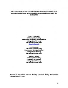
BIDIRECTIONAL UPDATE DEPENDENCY RELATION PATTERN
MERGE
DEVELOPMENT PHASE N TOOL A
DEVELOPMENT PHASE M TOOL B
TIME Fig. 4. Bidirectional Update Dependency Relation
6.1
Context
Application of the B ACKWARD U PDATE D EPENDENCY R ELATION pattern leads to problems if the original model has been evoluted concurrently with the development of the derived model. Updating of model artifacts of the original model with information from the derived model leads to information losses and is not possible. To put it differently, both models change their common artifacts. Hence, a form of synchronization is required to conjoin the enhancements of both models. 6.2
Problem
Concurrent development processes with mutual impacts on each other must lead to consistent result, regardless of sequential order, and mutual dependencies. 6.3
Forces
—Limited time-to-market and different required domain-expertise require a structuring to ensure concurrent working of departments. —Constraints affecting the system as a whole are too complex to be managed as a whole. —Cross-domain constraints cannot be separated and affect independent parts of the model. 6.4
Solution
Make data serving as basis for related models explicit. Change data in a concurrent model and trigger synchronization of other models. The B IDIRECTIONAL U PDATE D EPENDENCY R ELATION pattern shall be used for full concurrency development of mutually dependent models. Incorporate the F ORWARD U PDATE D EPENDENCY R ELATION pattern and the B ACKWARD U PDATE D EPENDENCY R ELATION pattern, including the synchronization of both. Figure 4 shows that both models are updated in parallel and change information on which they mutual dependent. As can be seen in the figure, this pattern also requires additional merging strategies to prevent from data corruption or race-conditions. Therefore, data serving as basis for concurrent models must be highlighted and made explicit. Changes of the data basis must be synchronized with the representation within the other model. Hence, synchronization Model Transformation and Synchronization Process Patterns — Page 9
techniques, such as diff and merge, are required. If a merging is not supported at least diff must be available to support the review of changes. For starting of concurrent development models, the data serving as basis for the models are used to generate the concurrent models and highlighted as shared data. The development of the two concurrent models can then be independent from another, as long as the shared data do not change. In case of a change of the shared data, a merging of the new information of both models is required. Supporting of such a synchronization is not easy and requires an adequate synchronization mechanism. Nevertheless, synchronization of the models is crucial and has to be managed with care. 6.5
Consequences
+ Splitting of work packages allows a separation of responsibilities and concurrent development of individual work-packages. + Divided responsibilities support optimized solutions of individual work-packages, due to working in expert groups with special-purpose models. + Split of responsibility of overall argumentation to domain experts for their sub-parts (possible due to splitting of models into special-purpose model). - Additional consolidation of the work-packages and overall system required (especially for system-wide features). - Individual optimal solutions may not result in the overall optimal solution (aka Vasa syndrome). - Requires additional merging activities of the work-packages (due to concurrent changing of models and to prevent from information losses). - Requires tracing of changes and change impact for merging activity (minor changes in one concurrent model may lead to major changes in the related models). 6.6
Known Uses
Classical approach of concurrent hardware and software development of embedded systems. Related patterns are: Cooperative Application Lifecycle Management pattern and Coordinative Application Lifecycle Management pattern. 6.7
Example
For example: A first design of the software architecture and its interface is done in context of system engineering to establish a hardware software interface document and enable concurrent development of HW and SW models. This SW architecture is transferred (e.g. application of F ORWARD U PDATE D EPENDENCY R ELATION pattern) into a more concrete model for SW development (such as Matlab/Simulink models). During SW development some SW interfaces change (e.g. signal resolution) in the concrete SW model (Matlab/Simulink model), while also in the original model (at system development) the SW architecture interfaces change due to some miss-alignment at HW level (e.g. signal is remapped to another pin). If B ACKWARD U PDATE D EPENDENCY R ELATION pattern would be used to update the original model the changes done in concurrency get lost or inconsistency occur. 7.
CONCLUSION
To sum up, the three presented patterns present concurrent workflows of the embedded system development domain. The pattern can be used to identify dependencies and consequences of concurrent workflows and thus, enable to cover the whole development life cycle using model-driven development approaches. This paper highlights these dependencies to enable the identification of such demands and overcome tool-breaks with adequate tool-bridging approaches. Model Transformation and Synchronization Process Patterns — Page 10
Acknowledgments The authors would like to express their thanks to our shepherd Johannes Koskinen who had a determining influence on the improvement of our paper and untiringly helped to improve the maturity of the paper in several iterations. REFERENCES A LEXANDER , C., I SHIKAWA , S., S ILVERSTEIN , M., J ACOBSON , M., F IKSDAHL -K ING , I., AND A NGEL , S. 1977. A Pattern Language. Oxford University Press, New York . A SPLUND, F., B IEHL , M., E L - KHOURY, J., F REDE , D., AND T HOERNGREN , M. 2012. Tool Integration, from Tool to Tool Chain with ISO 26262. In SAE Technical Paper. SAE International. B ROY, M., F EILKAS , M., H ERRMANNSDOERFER , M., M ERENDA , S., AND R ATIU, D. 2008. Seamless Model-based Development: from Isolated Tool to Integrated Model Engineering Environments. IEEE Magazin. E BERT, C. AND J ONES , C. 2009. Embedded Software: Facts, Figures, and Future. IEEE Computer Society 0018-9162/09, 42–52. G IESE , H., H ILDEBRANDT, S., AND N EUMANN , S. 2010. Model Synchronization at Work: Keeping SysML and AUTOSAR Models Consistent. LNCS 5765, pp. 555 –579. H OLTMANN , J., M EYER , J., AND M EYER , M. 2011. A Seamless Model-Based Development Process for Automotive Systems. ISO - I NTERNATIONAL O RGANIZATION FOR S TANDARDIZATION. 2011. ISO 26262 Road vehicles Functional Safety Part 1-10. L IGGESMEYER , P. AND T RAPP, M. 2009. Trends in embedded software engineering. IEEE Software 26, 3, 19–25. P ETRISSANS , A., K RAWCZYK , S., V ERONESI , L., C ATTANEO, G., F EENEY, N., AND M EUNIER , C. 2012. Design of Future Embedded Systems Toward System of Systems - Trends and Challenges. European Commission. R ASCHKE , W., Z ILLI , M., L OINIG , J., W EISS , R., S TEGER , C., AND K REINER , C. 2014. Patterns of Software Modeling. In On the Move to Meaningful Internet Systems: OTM 2014 Workshops, R. Meersman, H. Panetto, A. Mishra, R. Valencia-Garcia, L. de Silva, I. Ciuciu, F. Ferri, G. Weichhart, T. Moser, M. Bezzi, and H. Chan, Eds. Lecture Notes in Computer Science Series, vol. 8842. Springer Berlin Heidelberg, 428–437. S ALINGAROS , N. 2000. The Structure of Pattern Languages. Architectural Research Quarterly 4, 149–161. S CURO, G. 2012. Automotive industry: Innovation driven by electronics. http://embedded-computing.com/articles/automotive-industryinnovation-driven-electronics/.
EuroPloP ’XX, July xx - xx, 20xx, Irsee, Germany Copyright is held by the owner/author(s). Publication rights licensed to ACM. ACM xxx-x-xxxx-xxxx-x ...$xx.00. http://dx.doi.org/xx.xxxx/xxxxxxx.xxxxxxx Model Transformation and Synchronization Process Patterns — Page 11