JOSEPH LAYOUT
9/5/08
1:04 PM
Page 20
Modeling Middleboxes Dilip Joseph and Ion Stoica, University of California at Berkeley Abstract The lack of a concise and standard language to describe diverse middlebox functionality and deployment configurations adversely affects current middlebox deployment, as well as middlebox-related research. To alleviate this problem, we present a simple middlebox model that succinctly describes how different middleboxes process packets and illustrate it by representing four common middleboxes. We set up a pilot online repository of middlebox models and prototyped model inference and validation tools.
M
iddleboxes, like firewalls, NATs, load balancers, and intrusion-prevention boxes have become an integral part of networks today. There is great diversity in how these middleboxes process and transform packets, and in how they are configured and deployed. For example, a firewall is commonly connected inline on the physical network path and transparently forwards packets unmodified or drops them. A load balancer, on the other hand, rewrites packet headers and contents and often requires packets to be explicitly IP addressed and forwarded to it. There is currently no standard way to succinctly describe the complexity and diversity of middlebox packet processing and deployment mechanisms. Middlebox taxonomies like RFC 3234 [1] provide only a high-level classification of middleboxes. Details about middlebox operations and deployment configurations often are buried in different middlebox and vendor specific configuration manuals or simply are not documented clearly. Efforts like the Unified Firewall Model [2] and BEHAVE [3] provide models to describe the operations of specific middleboxes like firewalls and NATs. The lack of a concise and standard language to describe different middleboxes adversely affects current middlebox deployment, as well as hinders middlebox-related research. Correctly deploying and configuring a middlebox is a challenging task by itself. Without a clear understanding of how different middleboxes process packets and interact with the network and with other middleboxes, network planning, verification of operational correctness, and troubleshooting become even more complicated. In our own research experience of designing and implementing the policy-aware switching layer [4] — a new mechanism to overhaul the ad hoc manner in which middleboxes are deployed in data centers today — the non-availability of clear information about how some middleboxes process packets led to initial design decisions that were wrong and that later manifested as hard-to-debug errors while testing. In this article, we present a general model to clearly and succinctly describe the functionality of a middlebox and deployment configurations. Through sets of pre-conditions and processing rules, the model describes the types of packets expected by a middlebox and how it transforms them. Later, we provide more details of our model and illustrate it by representing four common middleboxes. The middlebox model provides a standard language to concisely describe different middleboxes. We are building an
20
0890-8044/08/$25.00 © 2008 IEEE
online repository of middlebox models at http://www.middlebox.org, which we envision as filled with models of various commonly used middleboxes. To ease model construction, we prototyped a tool that infers hints about the operations of a particular middlebox through black box testing. We also prototyped a tool that validates the operations of a middlebox against its model and thus helps detect unexpected behavior. We discuss these and other applications of our model later.
The Model RFC 3234 [1] defines a middlebox as “an intermediary device performing functions other than the normal, standard functions of an IP router on the datagram path between a source host and destination host.” We refine this high-level definition of a middlebox to construct a simple model that describes various aspects of middlebox functionality and operations. A middlebox in our model consists of zones, input pre-conditions, state databases, processing rules, auxiliary traffic, and the interest and state fields deduced from the processing rules. In this section, we describe and illustrate our model using four common middleboxes — firewall, NAT, layer-4 load balancer, and SSL-offload capable layer-7 load balancer. Table 1 describes the notations used.
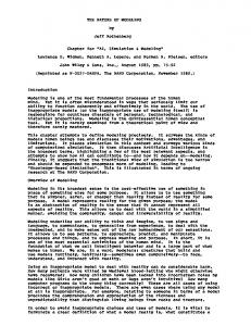
Interfaces and Zones Packets enter and exit a middlebox through one or more of its physical network interfaces. Each physical interface belongs to one or more logical network zones. A zone represents a packet entry and exit point from the perspective of middlebox functionality. A middlebox processes packets differently based on their ingress and egress zones. For example, the firewall shown in Fig. 1a has two physical interfaces, one belonging to the red zone that represents the insecure external network, and the other belonging to the green zone representing the secure internal network. Packets entering through the red zone are more stringently checked than those entering through the green zone. Similarly, the NAT in Fig. 1b has two different physical network interfaces, one belonging to the internal network (zone int) and the other belonging to the external network (zone ext). The source IP and port number are rewritten for packets received at zone int, whereas the destination IP and port number are rewritten for packets received at zone ext. Figure 1c shows a load balancer with a single physical network interface that belongs to two different zones — zone inet representing the
IEEE Network • September/October 2008
JOSEPH LAYOUT
9/5/08
1:04 PM
Page 21
∧
Logical AND operation
!
Logical NOT operation
sm
Source MAC (layer 2) address
dm
Destination MAC (layer 2) address
si
Source IP (layer 3) address
di
Destination IP (layer 3) address
sp
Source TCP/UDP (layer 4) port
dp
Destination TCP/UDP (layer 4) port
p
Packet
[hd]
Packet with header h and payload d
5tpl
Packet 5-tuple: si, di, sp, dp, proto
Xrev
Swaps any source-destination IP, MAC, or port number pairs in X
Z(A, p)
true if packet p arrived at or departed zone A
I (P, p)
Input precondition; true if packet p matches pattern P
C(p)
Condition specific to middlebox functionality
newflow?(p)
true if packet p indicates a new flow, e.g., TCP SYN
set(A, key → val)
Stores the specified key-value pair in zone A’s state database
S : get?(A, key)
Returns true and assigns val to S if key → val is present in zone A’s state database
n Table 1. Notations used in this article.
Internet and zone srvr representing the Web server farm. The load balancer spreads out packets received at zone inet to Web server instances in zone srvr. We assume that the mapping between interfaces and zones is pre-determined by the middlebox vendor or configured during middlebox initialization. Frames reaching an interface belonging to multiple zones are distinguished by their virtual local area network (VLAN) tags, IP addresses, and/or transport port numbers.
Input Preconditions Input preconditions specify the types of packets that are accepted by a middlebox for processing. For example, a transparent firewall processes all packets received by it, whereas a load balancer in a single-legged configuration processes a packet arriving at its inet zone only if the packet is explicitly addressed to it at layers 2, 3, and 4. Similarly, a NAT processes all packets received at its int zone, but requires those received at its ext zone to be addressed to it at layers 2 and 3. Input pre-conditions are represented using a clause of the form I (P, p), which is true if the headers and contents of packet p match the pattern P. For example, the firewall has the input precondition I (< * >, p), and the load balancer has I (< dm = MAC LB , di = IP LB , dp = 80 >, p) for its inet zone, where MAC LB and IP LB are the layer-2 and layer-3 addresses of the load balancer. Although I (< * >, p) is a tautology, we still explicitly specify it in the firewall model to enhance model clarity.
State Database Most middleboxes maintain state associated with the flows and sessions they process. Our model represents state using key-value pairs stored in zone-independent or zone-specific state databases. Processing rules (described next) record the state using the set primitive and query state using the get? primitive. Accurately tracking state removal is hard, unless explicitly specified by the del primitive in a processing rule. Although state expiration timeouts can be specified as part of the set primitive, inaccuracies in timeout values or in their fine-
IEEE Network • September/October 2008
grained measurement can cause discrepancies between the model predicted behavior of a middlebox and its actual operations. A middlebox behavior is predicted by the model. So the model predicted behavior of a middlebox may be better than its actual operations. As we illustrate in the next section, we use special processing rules to flag such possible discrepancies.
Processing Rules Processing rules model the core functionality of a middlebox. A processing rule specifies the action taken by a middlebox when a particular condition becomes true. For example, the processing of an incoming packet is represented by a rule of the general form: Z(A, p) ∧ I (P, p) ∧ C (p) ⇒ Z (B, T (p)) ∧ state ops The above rule indicates that a packet p reaching zone A of the middlebox is transformed to T(p) and emitted out through zone B, if it satisfies the input precondition I(P, p) and a middlebox-specific condition C(p). In addition, the middlebox may update state associated with the TCP flow or application session to which the packet belongs. We now present concrete examples of processing rules for common middleboxes. Firewall — First, consider a simple stateless layer-4 firewall that either drops a packet received on its red zone or relays it unmodified to the green zone. This behavior can be represented using the following two rules: Z(red, p) ∧ I(< * >, p) ∧ Caccept(p) ⇒ Z(green, p) Z(red, p) ∧ I(< * >, p) ∧ Cdrop(p) ⇒ DROP(p)
Since I(< * >, p) is a tautology, whether a packet is dropped or accepted by the firewall is solely determined by the Caccept and Cdrop clauses that represent the filtering functionality of the firewall. Common filtering rules can be represented easily using the appropriate Boolean expressions (e.g., Caccept(p) : p.di = 80 || p.si = 128.34.45.6). For more complex filtering rules, we leverage external middlebox-specific
21
9/5/08
1:04 PM
Page 22
Red zone (a)
Green zone
Insecure external network
External zone
(b) External network
Internal zone Internal network
NAT
Internet zone
Server zone
(c)
Internet
(iv), is keyed by [h.si, h.sp, h.di, h.dp] rather than by just [h.si, h.sp]. A symmetric NAT is also more restrictive than a full cone NAT. It relays a packet with header [IP s , IP NAT , PORTs, PORTd] from the ext zone only if it had earlier received a packet destined to IPs : PORTs at the int zone and had rewritten its source port to PORTd. This restrictive behavior is captured by keying the zone ext state set in rule (i) and retrieved in rules (iii) and (v) with [h.di, h.dp, newport] rather than with just newport. Other NAT types, like restricted cone and port restricted cone, can be easily represented with similar minor modifications.
Secure internal network
Web servers
JOSEPH LAYOUT
Switch
n Figure 1. Zones of different middleboxes: a) firewall; b) NAT; and c) load balancer in single-legged configuration. models like the Unified Firewall Model [2] to construct the appropriate C clauses. Rules for packets in the green → red direction are similar. NAT — Next, consider another very common middlebox — a NAT. Unlike the firewall in the previous example, a NAT rewrites packet headers and maintains per-flow state. We first describe the processing rules (rule box 1) for a full cone NAT and then, with minor modifications, change it to represent a symmetric NAT. Rule (i) describes how a full cone NAT processes a packet [hd] with a previously unseen [si, sp] pair received at its int zone. It allocates a new port number using a standard mechanism like random or sequential selection, or using a custom mechanism beyond the scope of our general model. It stores [si, sp] → newport and newport → [si, sp] in the state databases of zone int and zone ext, respectively. It rewrites the packet header h by applying the source NAT (SNATfwd) transformation function — the source medium access control (MAC) and IP addresses are replaced with the publicly visible addresses of the NAT, the source port with the newly allocated port number, and the destination MAC with the next hop IP gateway of the NAT. The packet with the rewritten header and unmodified payload is then emitted out through the ext zone. Rule (ii) specifies that the NAT emits a packet with a previously seen [si, sp] pair through zone ext, after applying SNATfwd with the port number recorded in rule (i). Rule (iii) describes how the NAT processes a packet reaching the ext zone. It retrieves the newport → [si, sp] state recorded in rule (i) using the destination port number of the packet, applies the reverse source NAT transformation function(SNATrev), and then emits the modified packet through zone int. Rule (iv) and Rule (v) flag discrepancies resulting from the inaccuracy of the model in tracking state expiration. The NAT may drop a packet arriving at its int or ext zone because the state associated with the packet expired without the knowledge of the model. Unlike a full cone NAT, a symmetric NAT allocates a separate port for each [si, sp, di, dp] tuple seen at its int zone, rather than for each [si, sp] pair. Thus, for a symmetric NAT, the zone int state set in rule (i) and retrieved in rules (ii) and
22
Layer-4 Load Balancer — Next, we present a layer-4 load balancer, which unlike the NAT in the previous example, rewrites the destination IP address of a packet to that of an available Web server (rule box 2). Rule (i) describes how the load balancer processes the first packet of a new flow received at its inet zone. The load balancer dynamically selects a Web server instance Wi for the flow and records it in the state database of the inet zone. It rewrites the destination IP and MAC addresses of the packet to Wi using the destination NAT (DNATfwd) transformation function and then emits it out through the srvr zone. It also records this flow in the state database of the srvr zone, keyed by the five-tuple of the packet expected there in the reverse flow direction. Rule (ii) specifies that subsequent packets of the flow simply will be emitted out after rewriting the destination IP and MAC addresses to those of the recorded Web server instance. Rule (iii) describes how the load balancer processes a packet received from a Web server. It verifies the existence of flow state for the packet and then emits it out through the inet zone after applying the reverse DNAT transformation — that is, rewriting the source IP and MAC addresses to those of the load balancer and the destination MAC to the next hop IP gateway. Although the Web server instance selection mechanism is beyond the scope of our general model, the load balancer model easily can be augmented with primitives to represent common selection mechanisms like least loaded and round robin. In the previous example, we assumed that the load balancer was set as the default IP gateway at each Web server. Other load balancer deployment configurations (e.g., direct server return or source NAT) can be represented with minor modifications. Layer-7 Load Balancer — We now present our most complex example, a layer-7 SSL offload-capable load balancer. This example illustrates how our model describes a middlebox whose processing spans both packet headers and contents and is not restricted to one-to-one packet transformations. The layer-7 load balancer is the end point of the TCP connection from a client (the CL connection). Because accurately modeling TCP is very hard, we abstract it using a black box TCP state machine tcp CL and buffer the data received from the client in a byte queue DCL. The I clauses are similar to those in the layer-4 load balancer and hence not repeated in rule box 3. Rule (i) specifies that the load balancer creates tcpCL and DCL and records them along with the packet header on receiving the first packet of a new flow from a client at the inet zone. Rule (ii) specifies how the TCP state and data queue of the CL connection are updated as the packets of an existing flow arrive from the client. Rule (iii), triggered when tcpCL has data or acknowledgments to send, specifies that packets from the load balancer to the client will have header hrev CL (with appropriate sequence numbers filled in by tcpCL) and payload read from the DLS queue, if it was already created by the firing of rule (iv). Rule (iv), triggered when the data collected in D CL is sufficient to parse the HTTP request URL and/or cookies, specifies that the load balancer selects a Web server instance Wi and opens a TCP connection to it, that is,
IEEE Network • September/October 2008
JOSEPH LAYOUT
9/5/08
1:04 PM
Z(int, [hd]) ∧ I(, [hd]) (i) ∧ IS : get?(int, [h.si, h.sp]) SNATfwd([sm, dm, si, di, sp, dp], PORT)
Page 23
Z(ext, [SNATfwd(h,newport)d]) ∧ set(int, [h.si, h.sp] – newport) ∧ set(ext,newport – [h.si, h.sp]) =[MACNAT,MACgw,IPNAT,di,PORT,dp]
Z(int, [hd]) (ii) ∧ I(, [hd]) Z(ext, [SNATfwd(h,S)d]) ∧ S : get?(int, [h.si, h.sp]) Z(ext, [hd]) ∧ I(, [hd]) ∧ S : get?(ext, h.dp)
Z(int, [SNATrev(h,S.si, S.sp)d])
SNATrev([sm, dm, si, di, =[MACNAT,MACIP,si,IP,sp,PORT] sp, dp], IP, PORT) Z(int, [hd]) DROP([hd]) (iv) ∧ I(, [hd]) ∧ WARN(inconsistent state) ∧ S : get?(int, [h.si, h.sp]) Z(ext, [hd]) ∧ I(, [hd]) ∧ S : get?(ext, h.dp)
DROP([hd]) ∧ WARN(inconsistent state)
n Rule box 1. creates tcp LS and DLS. It also installs a pointer to the state indexed by the DNATed header hLS in the state database of the srvr zone. Rule (v) shows how this state is retrieved, and its tcp LS and D LS are updated, on receipt of a packet from a Web server. Rule (vi) specifies the header and payload of packets sent by the load balancer to a Web server instance — hLS and data read from DCL. The rules listed above represent a plain layer-7 load balancer. By replacing the + and read data queue operations with +ssl and readssl operations that perform SSL encryption and decryption on the data, we can represent an SSL offloadcapable load balancer without disturbing other rules. Similar to the TCP black box, we abstract out the details of the SSL protocol.
Auxiliary Traffic In addition to its core functionality of transforming and forwarding packets, a middlebox can generate additional traffic, either independently or when triggered by a received packet. For example, a load balancer periodically checks the liveness of its target servers by making TCP connections to each server. It also can send an Address Resolution Protocol (ARP) request for the layer-2 address of the Web server assigned to a received packet. Such packets generated by middleboxes and their responses, which support middlebox functionality, are referred to as auxiliary traffic in our model. Auxiliary traffic is represented using processing rules, as well. For example, the auxiliary traffic associated with the load balancer can be represented in rule box 4. The PROBE function returns a set of packets to check the liveness of server W i. In the simple case, these are just the TCP hand-shake packets with the appropriate sm, dm, si, di, sp, and dp.
Interest and State Fields The interest fields of a middlebox identify the packet fields of interest, that is, the fields it reads or modifies. The state fields identify the subset of the interest fields used by the middlebox in storing and retrieving state. Although these fields can be deduced from the processing rules, they are explicitly presented in the model because they can highlight succinctly unexpected aspects of middlebox processing.
IEEE Network • September/October 2008
Utility of a Middlebox Model A middlebox model is useful only if it can easily represent many real-world middleboxes and has practical applications. In this section, we first describe how we constructed the models described in the previous section and then discuss the applications of our model in planning and troubleshooting existing middlebox deployments and in guiding the development of new network architectures.
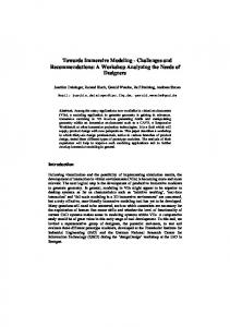
Model Instances The models for the firewall, NAT, and layer-4 and layer-7 load balancers illustrated in the previous section were constructed by analyzing generic middlebox descriptions and taxonomies (like RFC 3234 [1]), consulting middlebox-specific manuals, and observing the working of the following realworld middleboxes: • Linux Netfilter/iptables software firewall • Netgear home NAT • BalanceNg layer-4 software load balancer • HAProxy layer-7 load balancer Vmware appliance We prototyped a black box testing-based model-inference tool to aid middlebox model construction. The tool infers hints about the operations of a middlebox by carefully sending different kinds of packets on one zone and observing the packets emerging from other zones, as illustrated in Fig. 2. The following are some of the inferences generated by it: • The firewall does not modify packets; all packets sent by the tool emerge unmodified or are dropped. • The load balancers only process packets addressed to them at layers 2, 3, and 4. • The layer-4 load balancer rewrites the destination IP and MAC addresses of packets in the inet → srvr direction and the source addresses in the reverse direction. This inference was made by pairing and analyzing packets with identical payloads seen at the two zones of the load balancer. By using a relaxed payload similarity metric, the header rewriting rules for even the layer-7 load balancer were partially inferred. • The layer-4 load balancer caches source MAC addresses of packets processed by it in the inet → srvr direction and uses them in packets in the reverse direction. This inference was made by correlating rewritten packet header fields with values seen in earlier packets. Our inference tool is quite basic and serves only as an aid for model construction. It is not fully automated; for example, it requires the IP address and TCP port of the load balancer as input to avoid an exhaustive IP address search for packets
Z(inet, [hd]) ∧ I(,[hd]) ∧ newflow?([hd]) DNATfwd([sm, dm, si, di, sp, dp], W)
Z(srvr, [DNATfwd(h,Wi)d]) ∧ set(inet, h.5tpl – Wi) ∧ set(srvr, DNATfwd(h,Wi)rev.5tpl – true) = [SM,MACW,si,IPW,sp,dp]
Z(inet, [hd]) ∧ I(,[hd]) ∧ !newflow?([hd]) ∧ S : get?(inet, h.5tpl)
Z(srvr,[DNATfwd(h,S)d])
Z(srvr, [hd])^ I(,[hd]) ∧ S : get?(srvr, h.5tpl)
Z(inet,[DNATrev(h)d])
DNATrev([sm,dm,si,di,sp,dp]) = [MACLB,MACgw,IPLB,di,sp,dp]
n Rule box 2.
23
JOSEPH LAYOUT
(i)
9/5/08
1:04 PM
Z(inet, [hd]) ∧ I(...) ∧ newflow?([hd])
Z(inet, [hd]) ∧ I(...) (ii) ∧ !newflow?([hd]) ∧ S : get?(inet, h.5tpl)
Page 24
set(inet, h.5tpl – [tcpCL = TCP.new, DCL = Data.new, hCL = h])
S.tcpCL.rev(h) ∧ S.DCL+d
(iii) S.tcpCL.ready?
Z(inet, S.tcpCL.send(S.hrevCL,S.DLS.read))
(iv) S.DCL.url? Z(srvr, [hd])
S.hLS = DNATfwd(S.hCL, Wi) ∧ set(srvr,S.hrevLS.5tpl – S) ∧ S.DLS = Data.new ∧ S.tcpLS = TCP.new
(v) ∧ I(...) ∧ S : get?(srvr, h.5tpl)
S.tcpLS.recv(h) ∧ S.DLS+d
(vi) S.tcpLS.ready?
Z(srvr, S.tcpLS.send(S.hLS,S.DCL.read))
n Rule box 3. accepted by it. The inferred packet header transformation rules and state fields may not be 100 percent accurate and thus only serve to guide further analysis. For middleboxes like SSL offload boxes that completely transform packet payloads, the tool cannot infer the processing rules. We believe that completely inferring middlebox models through black box testing alone is impossible. If the source code for a middlebox implementation were available, we hypothesize that automatic white box software test-generation tools like directed automated random testing (DART) [5] can be adapted to infer middlebox model parameters. Automatically parsing middlebox configuration manuals to extract models is another open research direction. We envision an online repository containing models of common middleboxes. We set up a pilot version of such a repository at http://www.middlebox.org with the models described in this article. We hope that middlebox manufacturers and network administrators who use middleboxes will contribute additional models to the repository. We also prototyped a model validation tool that analyzes traffic traces collected from the different zones of a middlebox and verifies whether its operations are consistent with its model downloaded from the repository. Apart from flagging errors and incompleteness in the models themselves, the validation tool can be used to detect unexpected middlebox behavior, as we describe next.
Network Planning and Troubleshooting The middlebox model clearly describes how various middleboxes under different configurations interact with the network and with each other in a standard and concise format. This information aids in planning new middlebox deployments and in monitoring and troubleshooting existing ones. The input preconditions of a middlebox specify the types of packets expected by it and thus help a network architect plan the network topology and middlebox placement required to deliver the correct packets to it. The input preconditions and processing rules together help in analyzing the feasibility of placing different middleboxes in sequence. For example, because the right-hand sides of the firewall processing rules do not interfere with the conditions on the left-hand sides of the load balancer processing rules, the firewall can be placed in front of the load balancer with little scrutiny. However, placing the load balancer before the firewall requires more careful analysis as the destination address rewriting indicated by the processing rules of the load balancer may interfere with the Caccept and Cdrop clauses of the firewall. The middlebox processing rules specify the packets flowing in
24
PERIODIC
Z(srvr, PROBE(IPWi))
Z(inet,[hd]) ∧ S : get?(inet, h.5tpl) ∧ !S’ : get?(-,IPS)
Z(srvr, ARPREQ(IPS))
Z(srvr, ARPRPLY (IP, MAC)) set(-,IP – MAC)
n Rule box 4.
different parts of a network. This information can be used to statically analyze and detect problems with a middlebox deployment before actual network rollout. It also aids in troubleshooting existing middlebox deployments and enhances automated traffic monitoring and anomaly detection. For example, the model validation tool helped us detect unexpected NAT behavior in the home network of one of the authors. The author’s home NAT was not rewriting the source port numbers of the packets sent by internal hosts. The tool automatically flagged this behavior as a violation of rules (i) and (ii) of our NAT model. We expected the multiinterface home NAT to use source port translation to support simultaneous TCP connections to the same destination from the same source port on multiple internal hosts. The failure of such simultaneous TCP connections on further investigation confirmed the anomaly. Although a small example, this experience indicates that our middlebox model holds practical utility in detecting unexpected middlebox behavior.
Guide Networking Research Our middlebox model provides networking researchers with clear and concise descriptions of how various middleboxes operate. Such information is very useful for researchers, as well as companies involved in developing new network architectures, especially those that deal with middleboxes [6]. Not only does it provide hints to make a new architecture compatible with existing middleboxes, but it also helps identify middleboxes that cannot be supported. In retrospect, the availability of a middlebox model would have benefited our research greatly on designing the policyaware switching layer (PLayer) [4], alluded to earlier. The PLayer consists of enhanced layer-2 switches (pswitches) that explicitly forward packets to the middleboxes specified by a network administrator. In our original (erroneous) design, pswitches rewrote the source MAC addresses of packets processed by a transparent firewall to a unique dummy MAC address to mark packets that had already been processed by the firewall. Contrary to our expectation of the load balancer to use ARP, it cached the dummy source MAC addresses of packets in the forward flow direction and used them to address packets in the reverse direction. Such packets never reached their intended destinations. The presence of source MAC address in the interest and state fields of the load balancer would have helped us more quickly debug this problem. Moreover, it would have warned us against rewriting the source MAC address in our original design, thus avoiding a time-consuming redesign.
Limitations The model presented in this article is only a first step toward modeling middleboxes. Its three main limitations are: • The inability to describe highly-specific middlebox operations in detail • The lack of formal coverage proofs • The complexity of model specification The goal of building a general middlebox model that can describe a wide variety of middleboxes precludes our model from representing functionality that is very specific to a particular middlebox. We can extend our model easily using middle-
IEEE Network • September/October 2008
JOSEPH LAYOUT
9/5/08
1:04 PM
Page 25
Internet zone
Server zone
rower and more detailed focus on how middleboxes operate. Reference [10] uses detailed measurement techniques to evaluate the performance and reliability of production middlebox deployments. We plan to investigate how the techniques described in these papers can enhance our model inference and validation tools. Control Observe RFC 3234 [1] presents a taxonomy of middlepacket boxes. Our model goes well beyond a taxonomy sending and describes middlebox packet processing in Model inference tool more detail using a concise and standard language. In addition, our model can naturally induce a more fine-grained taxonomy on middleboxes n Figure 2. Middlebox model inference tool analyzing a load balancer. (e.g., “middleboxes that rewrite the destination IP and port number” versus “middleboxes operating at the transport layer”). Our model does not currently consider the middlebox failover modes and functional verbox-specific models like the Unified Firewall Model as sus optimizing roles identified by RFC 3234. described earlier, although at the expense of reducing model The Unified Firewall Model [2] and IETF BEHAVE [3] simplicity and conciseness. The desire for simplicity and conworking group characterize the functionality and behavior of ciseness also limits our model from capturing accurate timing specific middleboxes — firewalls and NATs in this case. Guidand causality between triggering of different processing rules. ed by these efforts, we construct a general model that applies On the other hand, our model may not be general enough to a wide range of middleboxes and enables us to compare to describe all possible current and future middleboxes. different middleboxes and study their interactions. FurtherAlthough we represented many common middleboxes in our more, these specific models can be plugged into our general model and are not aware of any existing middleboxes that model and alleviate the limitations of model generality. cannot be represented, we are unable to formally prove that our model covers all possible middleboxes. The model for a particular middlebox consists of a small Conclusion number (typically < 10) of processing rules. However, constructing the model itself is a non-trivial task even with support In this article, we presented a simple middlebox model and from our model inference and validation tools. We expect illustrated how various commonly used middleboxes can be models to be constructed by experts and shared through an described by it. The model guides middlebox-related research online model repository, thus making them easily available to and aids middlebox deployments. Our work is only an initial all, without requiring widespread model construction skills. step in this direction and calls for the support of the middlebox research and user communities to further refine the model and to contribute model instances for the many differRelated Work ent kinds of middleboxes that exist today. The middlebox model described in this article is placed at an interReferences mediate level in between related work on very general network [1] “Middleboxes: Taxonomy and Issues,” RFC 3234. communications models and very specific middlebox models. [2] G. J. Nalepa, “A Unified Firewall Model for Web Security,” Advances in An axiomatic basis for communication [7] presents a general Intelligent Web Mastering. network communications model that axiomatically formulates [3] “Behavior Engineering for Hindrance Avoidance”; http://www.ietf.org/ html.charters/behave-charter.html packet forwarding, naming, and addressing. This article presents [4] D. Joseph, A. Tavakoli, and I. Stoica, “A Policy-Aware Switching Layer for a model tailored to represent middlebox functionality and operData Centers,” Proc. SIGCOMM, 2008. ations. The processing rules and state database in our model are [5] P. Godefroid, N. Klarlund, and K. Sen, “DART: Directed Automated Random similar to the forwarding primitives and local switching table in Testing,” Proc. PLDI, 2005. [6] M. Walfish et al., “Middleboxes No Longer Considered Harmful,” Proc. [7]. As part of future work, we plan to investigate the integraOSDI, 2004. tion of the two models and thus combine the practical benefits [7] M. Karsten et al., “An Axiomatic Basis for Communication,” Proc. SIGof our middlebox model (e.g., middlebox model inference and COMM ’07. validation tools, model repository) and the theoretical benefits [8] T. Roscoe et al., “Predicate Routing: Enabling Controlled Networking,” SIGCOMM Comp. Commun. Rev., vol. 33, no. 1, 2003. of the general communications model (e.g., formal validation of [9] S. Kandula, R. Chandra, and D. Katabi, “What’s Going On? Learning Compacket forwarding correctness through chains of middleboxes). munication Rules in Edge Networks,” Proc. SIGCOMM, 2008. Predicate routing [8] attempts to unify security and routing [10] M. Allman, “On the Performance of Middleboxes,” Proc. IMC, 2003. by declaratively specifying network state as a set of Boolean Biographies expressions dictating the packets that can appear on various DILIP JOSEPH (
[email protected]) received his B.Tech. degree in computer science links connecting together end nodes and routers. This from the Indian Institute of Technology, Madras, in 2004 and his M.S. degree in approach can be extended to represent a subset of our midcomputer science from the University of California at Berkeley in 2006. He is currentdlebox model. For example, Boolean expressions on the ports ly a Ph.D. candidate at the University of California at Berkeley. His research interests and links (as defined by predicate routing) of a middlebox can include data center networking, middleboxes, and new Internet architectures. specify the input preconditions of our model and indirectly ION STOICA (
[email protected]) received his Ph.D. from Carnegie Mellon hint at the processing rules and transformation functions. University in 2000. He is an associate professor in the EECS Department at the From a different perspective, middlebox models from our University of California at Berkeley, where he does research on peer-to-peer netrepository can aid the definition of the Boolean expressions in work technologies in the Internet, resource management, and network architectures. He is the recipient of the 2007 Rising Star Award, a Sloan Foundation a network implementing predicate routing. Fellowship (2003), a Presidential Early Career Award for Scientists and EngiReference [9] uses statistical rule mining to automatically neers (PECASE) (2002), and the ACM doctoral dissertation award (2001). In group together commonly occurring flows and learn the under2006 he co-founded Conviva, a startup company to commercialize peer-to-peer lying communication rules in a network. Our work has a nartechnology for video distribution.
IEEE Network • September/October 2008
25