APPLIED PHYSICS LETTERS
VOLUME 73, NUMBER 10
7 SEPTEMBER 1998
Modeling of the ion mass effect on transient enhanced diffusion: Deviation from the ‘‘11’’ model Lourdes Pelaza) and G. H. Gilmer Bell Labs, Lucent Technologies, 700 Mountain Avenue, Murray Hill, New Jersey 07974
M. Jaraiz Universidad. de Valladolid, Campus Miguel Delibes s/n, 47011 Valladolid, Spain
S. B. Herner,b) H.-J. Gossmann, D. J. Eaglesham, G. Hobler,c) and C. S. Rafferty Bell Labs, Lucent Technologies, 700 Mountain Avenue, Murray Hill, New Jersey 07974
J. Barbolla Universidad. de Valladolid, Campus Miguel Delibes s/n, 47011 Valladolid, Spain
~Received 2 June 1998; accepted for publication 7 July 1998! The influence of ion mass on transient enhanced diffusion ~TED! and defect evolution after ion implantation in Si has been studied by atomistic simulation and compared with experiments. We have analyzed the TED induced by B, P, and As implants with equal range and energy: TED increases with ion mass for equal range implants, and species of different mass but equal energy cause approximately the same amount of TED. Heavier ions produce a larger redistribution of the Si atoms in the crystal, leading to a larger excess of interstitials deeper in the bulk and an excess of vacancies closer to the surface. For high-mass ions more interstitials escape recombination with vacancies, are stored in clusters, and then contribute to TED. TED can be described in terms of an effective ‘‘1n’’ or ‘‘plus factor’’ that increases with the implanted ion mass. © 1998 American Institute of Physics. @S0003-6951~98!01836-1#
Ion implantation plays a critical role for producing integrated circuits. However, the damage generated during ion implantation induces transient enhanced diffusion ~TED! in dopants that diffuse interstitially, and causes significant spreading of the dopant beyond the implanted region. This occurs during the anneal necessary to cure the damage and to activate the dopants electrically. In order to model TED, the ‘‘11’’ model has been used with satisfactory results in many cases.1 The idea behind the 11 model is that TED is mainly produced by the interstitial generated by the implanted ion as it becomes substitutional. The large number of Frenkel pairs created during ion implantation quickly recombine and do not contribute significantly to TED. This approach was shown experimentally to be accurate when P was implanted at different energies and tilt angles, producing different numbers of Frenkel pairs, with very similar distribution of the implanted ions.2 It was also found that for Si implants most of the TED occurs during the dissolution of the $311% defects, and the number of Si interstitials stored in them initially was found to be approximately equal to the implanted dose.3 Atomistic simulations have also shown that the main contribution to the enhanced diffusivity is due to the extra interstitial left once all the Frenkel pairs recombine.4 These results were obtained with P or Si, intermediate energies and doses below the amorphization threshold in the order of 531013 cm22. The 11 model along with random walk theory5 provides a!
Permanent address: Universidad de Valladolid, Campus Miguel Delibes s/n, 47071 Valladolid, Spain. Electronic mail:
[email protected] b! Present address: Applied Materials, Santa Clara, CA. c! Permanent address: University of Technology of Vienna, A-1040 Vienna, Austria.
a basic and intuitive understanding of TED. For dilute concentrations, TED is proportional to the number of Si interstitial hops per lattice position, which is a measure of the number of opportunities for a dopant atom to pair with a Si interstitial. Based on random walk arguments, the number of hops ~N! required for a single interstitial to move a distance R on average is proportional to (R/l) 2 , where l is the hop distance. If we assume that these hops are homogeneously distributed in a band extending from the surface to a depth that scales with R, the density of hops per unit volume is proportional to R. According to the 11 model the initial positions of the Si interstitials responsible for TED mirror the implanted ions. Then, as a first approximation, TED is proportional to the dose and to the distance of the implanted profile to the surface, where the Si interstitials are annihilated. It has been observed that for a given species of implanted ion and subamorphizing doses, TED increases with the energy of the ions,6,7 being approximately proportional to the range of the implanted ions,6 in agreement with the above model. It has also been found that, for a given energy, the resulting TED is approximately independent of the implant species.7,8 This observation contradicts the 11 model since, for a given energy, the range of heavier implanted ions is smaller and therefore, less TED is expected with increasing ion mass. In this letter, we will show that this situation arises from the fact that the 11 model includes only the interstitial generated by the implanted ion, and ignores the Frenkel pairs. The aim of this letter is to provide, through detailed atomistic simulations, a physical understanding of the dependence of TED on implanted species and to provide a simple
0003-6951/98/73(10)/1421/3/$15.00 1421 © 1998 American Institute of Physics Downloaded 13 Jan 2003 to 128.8.92.37. Redistribution subject to AIP license or copyright, see http://ojps.aip.org/aplo/aplcr.jsp
1422
Appl. Phys. Lett., Vol. 73, No. 10, 7 September 1998
Pelaz et al.
FIG. 2. ~a! Net profile of Si interstitials and vacancies as obtained from MARLOWE simulations. ~b! Si interstitial profile after recombination during annealing at 750 °C.
FIG. 1. Experimental time averaged B diffusivity ~from Ref. 7! and simulated total number of Si interstitial hops per lattice site for ~a! equal range implants ~R p ;45 nm: 15 keV B, 35 keV P, and 80 keV As! and ~b! equal energy implants ~35 keV!, after 120 min at 750 °C anneal.
and more accurate way to estimate TED for different implanted ions. For our study, we use a binary collision code, 9 MARLOWE, to generate the implantation cascades. The coordinates of all interstitials and vacancies are transferred to a Monte Carlo diffusion code to simulate room temperature diffusion and subsequent annealing at high temperature, following the scheme described in Ref. 4. Si interstitials and vacancies are moved randomly to neighboring sites according to their respective diffusivities until they recombine, are trapped, or annihilated at the front or back surface. The simulation box has an area of 45345 nm2 and a depth of 4000 nm to minimize the effect of the back surface. We consider uniform implants across the sample with B, P, As ions, 2 31013 ions/cm2 doses and annealing at 750 °C for 120 min, as in the experiment reported by Griffin et al.7 We analyze implants in which the energy has been chosen to provide approximately the same projected range for all species ~15 keV for B, 35 keV for P, and 80 keV for As! and also implants with the same energy ~35 keV!. In the experiment, the authors use a B marker layer of 1018 cm23, 200 nm wide at a depth of 400 nm to monitor the enhanced diffusion induced by the implanted ions. From the diffused B profile they extract a time average B diffusivity (D B) over the 120 min anneal and compare it to the B diffusivity without implantation (D B* ). Since B diffuses by the kick-out mechanism,10 the enhanced B diffusivity is proportional to the number of Si interstitial hops per lattice site. Figure 1 shows the enhanced B diffusivity as measured in the experiment7 compared with the total number of Si interstitial hops per lattice obtained in the simulation at 500 nm ~the average depth of the B marker layer in the experiment!. Simulations including all the Frenkel pairs generated
by MARLOWE, and by using the 11 model, are plotted. We implement the 11 model by placing a Si interstitial in the position of the implanted ion, without the Frenkel pairs. As described above, the 11 model predicts that TED is proportional to the projected range of the implanted ion, independent of the ion mass. However, this result differs significantly from the experimental results. The simulation results in which we include all the implantation damage agree with the experimental data:7 TED increases with ion mass for equal range implants, with As causing twice the diffusion of B. TED only changes 20% for the equal energy implants of B, P, and As, although the range decreases more than a factor of four going from B to As. An analysis of the damage profile indicates that different implanted species produce different amounts and distributions of the damage. Heavy ions produce more and denser damage because of the larger momentum and cross section of the implanted ion and because the electronic losses are less. However, overlapping Frenkel pairs do not contribute significantly to TED, since interstitials do not visit many lattice sites before recombination with nearby vacancies. What is important is that heavy ions transfer more momentum to the target atoms, and therefore there is a larger net displacement of Si atoms deeper in the crystal, leaving vacancies closer to the surface. This effect can be clearly observed when the net profile obtained by subtracting vacancies from interstitials is plotted, as shown in Fig. 2~a!. The number of interstitials per implanted ion that correspond to the interstitial-rich zone is 1.02 for B, 1.20 for P, and 1.95 for As. The net number of total interstitials minus vacancies is lower than unity due to the sputtered atoms.11 The spatial separation between interstitials and vacancies implies that on average, more interstitials have to diffuse a greater distance to recombine with vacancies, since the vacancies are located close to the surface and the interstitials are much deeper. Also, being closer to the surface, many of the vacancies reach the surface before recombination with the interstitials, leaving behind an excess of interstitials, as shown in Fig. 2~b!. The number of Si interstitials that survive recombination is also indicated by the number of interstitials stored in clusters, which increases with the mass of the implanted ion. Heavier ions produce a larger number of Si interstitials
Downloaded 13 Jan 2003 to 128.8.92.37. Redistribution subject to AIP license or copyright, see http://ojps.aip.org/aplo/aplcr.jsp
Pelaz et al.
Appl. Phys. Lett., Vol. 73, No. 10, 7 September 1998
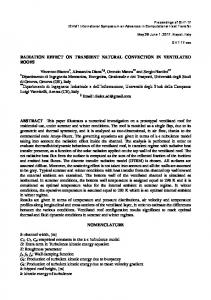
FIG. 3. Effective 1n vs ion mass. Symbols correspond to simulations with a constant dose of 1014 ions/cm2 and energy varying from 15 to 200 keV. The lines correspond to the empirical expression for 50, 100, and 200 keV.
stored in larger clusters. At 1 s, 2.3 interstitials per ion are still in interstitial clusters for As implants, while in the case of P there are only 1.14 interstitials and for B, only 0.84 interstitials per ion. The existence of a larger number of interstitials stored in clusters for heavier ion mass has been confirmed experimentally for Pb compared with Si implants.12 Since most of the TED occurs during the dissolution of the Si interstitial clusters, the number of Si interstitials stored in these clusters can give an idea of the expected TED. However, since this number evolves during the anneal, it is difficult to quantify TED based only on this observation. We define an effective plus-factor or ‘‘1n’’ as the ratio of the time integrated interstitial hops using the model with full damage to that from the 11 model. The 1n that we obtain by this method is 11.2 for 231013 cm22 dose and equal range implants for the case of B, 11.8 for P, and 12.7 for As. This 1n is larger than the net number of interstitials in the interstitial-rich zone for two reasons. First, the center of mass of the profile of the net interstitials is deeper than that of the implanted profile. Second, the interstitial diffusion occurring during the recombination of the overlapping damage adds to the interstitial hops. This contribution increases with lower doses since the concentration of interstitials and vacancies is more dilute and interstitials have to diffuse some distance before finding other vacancies.13 We have calculated the effective 1n for different ions, for energies between 15 and 200 keV, and, a dose 1014 cm22 ignoring amorphization. The value of the effective 1n increases with ion mass, as shown in Fig. 3. We have found an analytical expression which fits the simulation values of the 1n. This expression includes the 11 corresponding to the implanted ion, and an additional term that depends on energy and ion mass as the momentum of the implanted ion; n511
0.42 R 3/4 p
AEm ,
1423
where R p is the projected range, E is the kinetic energy, and m is the mass of the implanted ion. Equal energy implants produce approximately the same amount of TED, independent of the ion mass, as shown in Fig. 1, because the increase in the effective 1n approximately compensates the reduction in the range for heavier ion mass. Thus, for 35 keV implants, the product of the depth of the center of mass of the implanted ions times the effective 1n is 149 nm for B, 123 nm for P, and 128 nm for As, which is a variation of less than 20%, although the range changes by a factor of four, in agreement with the experiment of Griffing et al.7 In summary, we have shown that for heavy implanted ions the damage distribution has an important effect on TED and defect evolution. The larger momentum transfer to the target atoms produced by heavy ions causes a larger redistribution of the Si atoms, i.e., more Si atoms are displaced deeper in the crystal than vacancies. This fact reduces recombination effectiveness of Frenkel pairs and produces an increase of the number of interstitials that are stored in clusters and that contribute significantly to TED. The 11 model can be corrected by estimating an effective 1n that includes not only the implanted ion but also a term that accounts for the inefficient recombination of Frenkel pairs. We have found that for larger doses, the 1n follows a dependence on mass and energy, as shown in the previous equation. One of the authors ~L.P.! acknowledges partial financial support from Fundacion Ramon Areces, Spain.
M. D. Giles, J. Electrochem. Soc. 138, 1160 ~1991!. M. D. Giles, S. Yu, H. W. Kennel, and P. A. Packan, Mater. Res. Soc. Symp. Proc. 469, 253 ~1997!. 3 D. J. Eaglesham, P. A. Stolk, H.-J. Gossmann, and J. M. Poate, Appl. Phys. Lett. 65, 2305 ~1994!. 4 M. Jaraiz, G. H. Gilmer, J. M. Poate, and T. Diaz de la Rubia, Appl. Phys. Lett. 68, 409 ~1996!. 5 For example, chapter 7 from D. R. Olander, Fundamental Aspects of Nuclear Reactor Fuel Elements ~ERDA, Technical Information Center, Oak Ridge, Tennesee, 1976!. 6 A. Agarwal, H.-J. Gossmann, D. J. Eaglesham, L. Pelaz, D. C. Jacobson, T. E. Haynes, and Y. E. Erokhin, Appl. Phys. Lett. 71, 3141 ~1997!. 7 P. B. Griffin, R. F. Lever, R. Y. S. Huang, H. W. Kennel, P. A. Packan, and J. D. Plummer, Tech. Dig. Int. Electron Devices Meet., 295 ~1993!. 8 H. S. Chao, S. W. Crowder, P. B. Griffin, and J. D. Plummer, J. Appl. Phys. 79, 2352 ~1996!. 9 M. T. Robinson and I. M. Torrens, Phys. Rev. B 9, 5008 ~1974!. 10 P. M. Fahey, P. B. Griffin, and J. D. Plummer, Rev. Mod. Phys. 61, 289 ~1989!. 11 G. Hobler, Proc. Electrochem. Soc. 96-4, 509 ~1996!. 12 S. B. Herner, H.-J. Gossmann, L. Pelaz, G. H. Gilmer, M. Jaraiz, D. C. Jacobson, and D. J. Eaglesham, J. Appl. Phys. 83, 6182 ~1998!. 13 L. Pelaz, G. H. Gilmer, M. Jaraiz, H.-J. Gossmann, G. Hobler, C. S. Rafferty, D. J. Eaglesham, and J. Barbolla ~unpublished!. 1 2
Downloaded 13 Jan 2003 to 128.8.92.37. Redistribution subject to AIP license or copyright, see http://ojps.aip.org/aplo/aplcr.jsp