Proceedings of the World Congress on Engineering 2012 Vol III WCE 2012, July 4 - 6, 2012, London, U.K.
Modeling the Low Initial Engine Start Up Speed 1st Compression Ring EHL S. Adnan Qasim, Rashid Naseer, Abdul Ghafoor, M. Afzaal Malik.
Abstract—The 1st compression ring sustains the maximum thermal loads during the operation of an internal combustion engine. In the initial engine start up at a very low speed, the secondary displacements of the piston affect the lubrication of the 1st compression ring adversely in the absence of a fully developed elastohydrodynamic lubricating (EHL) film. The adverse effects may allow a physical contact and wear of the ring and the liner surfaces. This study develops the numerical models of the hydrodynamic and EHL of the 1st compression ring at a very low initial engine start up speed. Then the results are compared with those at the other two low speeds, considered separately. The secondary dynamics of the piston ring assembly and the barrel-face profile of the ring are incorporated in the models. The Reynolds equation is solved to generate the hydrodynamic pressures, developed over the circumferential length of the ring. The inverse solution technique is employed to study the rising EHL pressures and the EHL film profiles after incorporating the elastic surface displacements in the models. The simulation results show the hydrodynamic and EHL film thicknesses as the function of the 720 - degree crank rotation cycle. The simulation results show that a low engine start up speed affects the ring lubrication and the load carrying capacity of the film of a low-viscosity grade lubricant. The low engine start up speed is optimized based on the findings of the comparative analysis of the results to improve the ring lubrication for a few initial cycles.
Index Terms— EHL, 1st Compression Ring, Modeling, Initial Engine Start up.
I. INTRODUCTION In a few initial engine start up cycles an effective lubrication of the piston ring assembly has always been a challenging issue. The initial engine start up process is essentially transient in nature. Despite assuming oil flooding the engine start up wear cannot be avoided due to the initial transients and in the absence of a fully established elastohydrodynamic lubricating (EHL) film between the piston ring assembly and the cylinder liner [1]. The 1st compression ring experiences the most severe engine operating conditions and the time-dependent alternating loads. It has the barrel or the parabolic face profile with the wear resistant coating on it [2]. The parabolic profile is preferred because the ring tends to be self-perpetuating under wear and rocks inside its groove This work was sponsored by National University of Sciences and Technology (NUST), Islamabad, Pakistan. Financial support was provided by the Higher Education Commission of Pakistan. Syed Adnan Qasim is research associate at NUST College of Electrical and Mechanical Engineering, (email:
[email protected]) Rashid Naseer is graduate student at NUST School of Mechanical and Manufacturing Engineering, (email:
[email protected]) Abdul Ghafoor is Professor and Dean at NUST School of Mechanical and Manufacturing Engineering (email:
[email protected] ) M. Afzaal Malik is Professor at Department of Mechanical and Aerospace Engg, Air University. (email:
[email protected])
ISBN: 978-988-19252-2-0 ISSN: 2078-0958 (Print); ISSN: 2078-0966 (Online)
during the reciprocating movement. It causes the preferential wear of the edges of the ring [3]. In view of the crucial role assigned to the compression ring its lubrication has always fascinated the researchers. In one of the experimental studies, the measurements of the thickness of the film between the ring and the liner showed that the lubricant behavior was essentially hydrodynamic throughout the stroke at the different speeds and loads during the normal engine operation. The film thickness was found increased with the engine speed and the lubricant viscosity [4]. A comparison of the measured and the calculated thickness of the films between the ring and the liner showed that the measured film was considerably thicker than the one calculated from the theoretical results [5]. A follow up work explained that if the inlet region of the compression ring was kept fully flooded the film thickness obeyed the theoretical results [6]. The results of a related experimental investigation showed that the film thickness profile varied along the circumferential axis and peak to peak surface roughness decreased due to the time of the engine running [7]. Under the flooding conditions in a few low-speed initial engine start up cycles the thickness of the film is marginally low due to shear heating. It allows a physical contact between the piston assembly and the cylinder liner that causes wear of the interacting surfaces [8]. Based on the calculations the film thickness profiles are generated in the hydrodynamic lubrication model of the ring. The piezoviscous effects are introduced and incorporated in the EHL model by defining the pressure-viscosity relationship. The elastic displacements of the interacting ring and liner surfaces are incorporated to obtain the profiles of the EHL film and the rising pressures. The simulation results of the hydrodynamic and EHL models are compared with those at the other two speeds to analyze the effects of low speed on the film thickness and pressures in the hydrodynamic and EHL regimes. The following assumptions are considered in the models: 1. Newtonian lubricant with thermal effects neglected 2. Relative motion between ring and groove is neglected. 3. Surface waviness and roughness are neglected. 4. Pressure at the inlet of contact zone is zero. 5. Flow is laminar and turbulence effects are neglected. 6. Surfaces are oil-flooded at the time of engine start up. Table-1 (Input Parameters) Parameter Value Parameter Value
R
0.0415 m
Ɵ = 𝛉1 + 𝛉 2 l
L
0.0338 m
η
0.03187 Pa.S. 0.3
E1
200 GPa
0.295 kg
0.09 kg
R
0.0418 m
75 degree 0.133 m
WCE 2012
Proceedings of the World Congress on Engineering 2012 Vol III WCE 2012, July 4 - 6, 2012, London, U.K. ring inside the groove is ignored. The contact geometry as a function of the secondary piston displacements is [9]:
II. MATHEMATICAL MODEL A.
Governing Equations of Piston and Ring Motion
The mathematical relationships dealing with the secondary dynamics of the piston and the 1st compression ring are defined. The secondary eccentricities or displacements of the piston assembly along the direction perpendicular to the axis of cylinder are defined. For the constant crankshaft speed , the ring speed is the same as that of the piston, which is [8, 9]: (1) where
(2)
The piston and the ring assembly displace eccentrically in the transverse direction. The displacements or eccentricities are time-dependent and the second-order changes are anticipated. In view of this, the second-order secondary displacements of the piston and the ring in the transverse direction are calculated. The inertia of the piston assembly, the forces that act and the moments produced are considered in equilibrium conditions. These are incorporated in the form suggested by Zhu et al [8, 9]: (3)
(10) Neglecting the tilt of the ring, the barrel shaped ring face can be defined as a set of polynomials, given by [10, 11]: h1 x s1 ( x 2 2a1 x a12 ) h1 x 0.00; a1 x a 2 h1 x s 2 ( x 2 2a 2 x a 22 )
y ;b / 2 x a1 L y ; a2 x b / 2 L
where, (11) s1, s2 = 2.0(10)-6 a1 = Ring face geometric parameter = -0.4 a2 = Ring face geometric parameter = 0.4 b = Effective ring thickness in axial direction = 0.001 (m) The contact geometry of the 1 st compression ring is the time dependent film thickness determined as a function of the gas pressure and the mean hydrodynamic pressure. It is given by: h0 (t )
( pM p g ) r 2
(12)
Et r
where, pg = Internal gas pressure. pM = Mean hydrodynamic pressure. E = Young’s modulus of the ring (E = 113.79 GPa). tr = Ring radial thickness (0.0015 m)
(3a)
(3c)
After considering the secondary displacements of the piston assembly, the resultant film thickness of the 1st compression ring is the sum of the time-dependent film, the barrel-face profile of the ring and the radial clearance:
(3d)
h h ho t h1 x C
(3b)
(13)
B Reynolds Equation and Hydrodynamic Pressure
E. Film Thickness in EHL Regime
The Reynolds equation is solved numerically to determine the hydrodynamic pressures. The hydrodynamic pressures develop over the surface of the piston skirts as well as between the ring and the cylinder liner. The 2-D Reynolds equation is [9]:
In the EHL regime the bulk elastic displacement is considered. The EHL film thickness is [9]: (14) where f(θ ,y) defines the profile due to manufacturing imperfections and is neglected. The differential surface displacement is [11, 12]:
(4) Boundary conditions for the Reynolds equation are [9]:
(15)
;
where
(16) (17)
(5) The elastic displacement at a specific point is [11, 12]:
C. Hydrodynamic Forces and Shear Stress The hydrodynamic and the friction forces are [9]: =
(8) The total normal force acting on the piston skirts is [9]: (9) D. Film Thickness in Hydrodynamic Regime The compression ring displaces along with the transverse eccentric piston displacements, as the relative motion of the
ISBN: 978-988-19252-2-0 ISSN: 2078-0958 (Print); ISSN: 2078-0966 (Online)
(18)
(6) (7) III.
NUMERICAL RESULTS AND D ISCUSSION
Equation (3) defines the second-order changes in the secondary displacements of the piston and ring assembly. It is an initial value problem to solve a pair of non-linear equations numerically. The values of et, eb, ėt and ėb are guessed at a previous time step, which become the initial values for the current time step to solve the equations (10)
WCE 2012
Proceedings of the World Congress on Engineering 2012 Vol III WCE 2012, July 4 - 6, 2012, London, U.K. and (13), respectively. The solution provides the thickness of the hydrodynamic film at the current time step. The equations governing the second-order changes in the axial and transverse displacements of the piston and ring assembly are solved numerically. The 2-D Reynolds equation is discretized and solved numerically. An appropriate size finite difference mesh is generated to determine the hydrodynamic pressures for the piston and the 1st compression ring, separately. The pressures developed over the piston skirts surface are used to initialize the secondary displacements of the ring in order to define its contact geometry as a function of the 4-stroke cycle. Based on the convergence criteria for the iterative procedure the solution for the hydrodynamic pressures is achieved based on the discretized Reynolds and the oil film thickness equations. Then all the forces and moments in equation (3) are calculated and computed in the accelerations ёt, ёb to satisfy from the solution of the velocities ėt, ėb at the previous and present time steps. When the secondary velocities ėt, ėb are satisfied, the piston position at the end of the current time step is determined as [9]:
The convergence criteria of the periodic solution is based on 4π = 720 degrees crank angle. The solution should satisfy [9]:
In the EHL regime the film thickness is calculated by using the three basic numerical procedures. The Reynolds equation is integrated in the first procedure. The integration gives the hydrodynamic pressure distribution for a known film thickness. Then the approach suggested by Dowson [12] is adopted by seeking the inverse solution of the Reynolds equation. The solution yields the profile of the thickness of the film. The film profile would engender a specified pressure distribution. The third procedure is to calculate the elastic deformation of the interacting ring and the liner. A. Ring Motion in the 4-stroke Cycle The lateral displacements of the ring in the transverse direction produce the desired wedging action necessary for the development of hydrodynamic pressures. It implies the development of the hydrodynamic load-carrying capacity of the lubricant to sustain the thrust of combustion in the form of the thermal loading. The 1st compression ring is directly exposed to the combustion loads. It requires the most effective lubrication to cater for all forms of the dynamic loads experienced by the piston ring assembly. The 1 st compression ring has to act as an effective seal to prevent the loss of power during the 4-stroke cycle. The 1st compression ring forms part of the piston assembly and hence displaces with the same cyclic speed as is the case of the piston. At the top and the bottom dead-centers i.e., TDC and BDC, the cyclic speed of the ring is negligible. In the induction stroke it commences its journey at zero degree crank rotation angle, accelerates with the piston and attains a maximum cyclic speed at the mid-stroke. Then it decelerates from the mid-induction stroke until the completion of the stroke at BDC when the crankshaft has completed the 180 degree rotation. In the compression stroke the 1st compression ring moves from the BDC to the TDC with the same cyclic speed,
ISBN: 978-988-19252-2-0 ISSN: 2078-0958 (Print); ISSN: 2078-0966 (Online)
as before and travels a distance equivalent to another 180 degrees rotation of the crankshaft. Although the ring has the same cyclic speed in both the induction and the compression strokes but the operating conditions inside the combustion chamber are different for both the strokes. In the induction stroke the intake valve is open and the air-fuel mixture is sucked into the chamber at a very low gas pressure. In the compression stroke the intake and the exhaust valves are closed and the already inducted air-fuel charge is compressed by the piston. The piston travels through the swept volume and pushes the mixture into the very small clearance volume. The piston action of compressing the charge increases the amplitude of the gas pressure force manifold. The gas force of high amplitude acts over the piston crown and the 1 st compression ring and affects the lateral displacements. At very high compression pressure the piston ring commences its journey in the expansion stroke at 361 degree of crank rotation cycle. Combustion occurs at 372 degree of the crank rotation angle and an exponential rise in the amplitude of the gas force produces a corresponding thrust over the surface of the 1st compression ring. The direction of the lateral secondary displacements of the piston assembly changes and the 1st compression ring comes closer to the liner surface. In the second half of the expansion stroke the effects of the combustion thrust subsides as the piston assembly decelerates along with the 1st compression ring. In the exhaust stroke the gap between the ring and the liner does not vary in the absence of any external force and the 1st compression ring completes the 4-stroke cycle as an active part of the piston assembly. B.
Ring Hydrodynamic Film Thickness Profiles
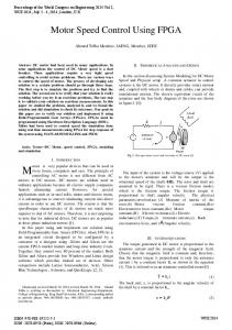
Figure 1 shows the maximum and the minimum film thickness profiles in the hydrodynamic regime at 600 rpm initial engine start up speed. The maximum film represents the thickness prior to the side leakage and the squeeze out of the lubricant. The minimum film is the thickness available after the leakages in the lateral and the longitudinal directions. The minimum film thickness represents the film, which actually carries the hydrodynamic load between the ring and the liner surfaces. In the hydrodynamic regime the lubricant flows between the 1st compression ring and the cylinder liner. At the same time it must establish a sufficiently thick film between the ring and the liner. The film profiles show the variations in the thickness of the film in all the 4-strokes of an engine cycle. The initially very thin film between the ring and the liner rises to around 4.5 microns at close to the mid-induction stroke. It drops instantaneously to a fraction of a micron as the ring decelerates after the mid-induction stroke. The film gets thicker as the ring commences its journey in the compression stroke. It drops swiftly due to the transverse displacement of the ring and the rising amplitudes of the gas force due to compression. The film gets thicker for the third time but this time it builds up gradually. The maximum and the minimum films attain the peak values prior to combustion. The thrust of combustion reduces the film thickness for the third time. However, it rises for the fourth time again during the second half of the expansion stroke as the effect of combustion subsides. If the initial engine start up speed increases to 700 and then 800 rpm, the thickness of the films changes in the induction and the exhaust strokes. The respective hydrodynamic film
WCE 2012
Proceedings of the World Congress on Engineering 2012 Vol III WCE 2012, July 4 - 6, 2012, London, U.K. profiles as the function of 720 degrees crank rotation cycle are shown in figures 2 and 3. C. Ring EHL Film Thickness Profiles The hydrodynamic pressures in the lubrication regime rise very high and resultantly the interacting ring and the liner line surfaces deform elastically. The sharply rising pressures compress the minimum film thickness and bring it to the level of a fraction of the micron thin. The thin film becomes thinner at the maximum hydrodynamic pressures prior to the deformation of the interacting line surfaces of the ring and the cylinder. The very thin film at the maximum pressures prior to the elastic line displacements is designated as the hpmax film and that after the elastic deformation is termed as the 'EHL Film'. The 'EHL Film ' is relatively thicker than the hpmax film due to the creation of the additional space because of the surface displacements at very high pressures. In the EHL regime the film thickness profiles at the three initially low engine start up speeds of 600, 700 and 800 rpm, respectively are shown in figures 4, 5 and 6. The profiles are generally similar but there are some noticeable differences. A significant difference in the profiles at the three speeds is observed in the expansion stroke. As the thrust load of combustion subsides in the second half of the expansion stroke an instantaneous spike is generated in all the three cases. The amplitude and the duration of the spike increase with the engine speed. Apart from the different instantaneous spikes the film profiles are generally similar in the expansion and the exhaust strokes. D.
4-stroke cycle. The six piston positions are selected where there are visible changes in the profiles and the shape of the gradients. The pressure fields may be compared with those at 700 and 800 rpm speeds as in figures 8 and 9, respectively. E
Pressure Rise in EHL Regime
The amount of energy transferred continuously from the ring to the liner and vice versa allows the build up and the accumulation of the gas force thrust at the greater proportions. The energy transfer rate allows the 1st compression ring to sustain the loads effectively. However, the excess loading over a period of time invites the elastic displacement of the ring and the liner. In view of the very high pressures rising over the line surface zone of the ring and the cyclic loading, the amplitude of the rising EHD pressures should be plotted graphically and analyzed. In view of this the figures 10, 11 and 12 show the extent of the EHD pressures rising over the circumferential length of the ring. The 3-D profiles are plotted for the better comprehension of the stated numerical results. The dimensionless pressure fields show that the maximum pressures rising over the ring are around 1.2 % at 600 rpm speed. If the engine start up speed is enhanced to 700 or 800 rpm, then the EHD pressures will also increase correspondingly. By increasing the start up speed to 700 rpm the peak EHD pressures rise to around 6%. If the speed is enhanced to 800 rpm then the pressures would rise further to around 8%. The intensities of the rising EHD pressures also change with the engine start up speed. It shifts the bias of pressures from one place to the other in the ring.
Hydrodynamic Pressures
The 1st compression ring has a circular shape and is placed conformal to the cylinder liner. Due to the wedging action the hydrodynamic pressures build up along the entire circumferential length of the ring. It enables the1 st compression ring to carry the hydrodynamic loads successfully and acts as an effective seal in the face of the tremendous thrust of combustion. The low hydrodynamic pressures build up in the induction and the exhaust strokes. It happens in the absence of any significant external force transferring energy for the subsequent hydrodynamic action. The hydrodynamic loading is essentially attributed to the secondary transverse displacements of the 1st compression ring alongside the piston assembly. In the compression and expansion strokes the primary source of energy transfer causing the hydrodynamic action is the action of the gas pressure force. The transverse displacements of the ring as a source of energy transfer take the secondary role. In the induction and the exhaust strokes the hydrodynamic pressures build up gradually over the entire 360 degree circumferential length of the ring. The low-intensity pressures have gentle slopes and rise to attain the peak values at the mid-zone of the circumferential axis of the ring. In the compression stroke the pressures intensify with steep gradients and pointed peaks drifting away from the central zone. The 1st compression ring experiences the maximum hydrodynamic loading just after combustion. Resultantly, the pressure gradients change rapidly to sustain the thrust of combustion. Figure 7 shows the hydrodynamic pressure fields at 600 rpm initial engine start up speed. The pressures are shown building up over the circumferential length of the ring at the six out of the 720 piston positions available in the
ISBN: 978-988-19252-2-0 ISSN: 2078-0958 (Print); ISSN: 2078-0966 (Online)
Fig:1 Film Profiles at 600 rpm in Hydrodynamic Regime
Fig:2 Film Profiles at 700 rpm in Hydrodynamic Regime
Fig:3 Film Profiles at 800 rpm in Hydrodynamic Regime
WCE 2012
Proceedings of the World Congress on Engineering 2012 Vol III WCE 2012, July 4 - 6, 2012, London, U.K.
(a)
(b)
(c)
Fig:4 Film Profiles at 600 rpm in Hydrodynamic & EHL
(d) (e) (f) Fig:8 At 700 rpm Dimensionless Hydrodynamic Pressures at Angle in degrees (a) 90 (b) 270 (c) 360 (d) 540 (e)630(f)720
Fig:5 Film Profiles at 700 rpm in Hydrodynamic & EHL (a)
(b)
(c)
(d) (e) (f) Fig:9 At 800 rpm Dimensionless Hydrodynamic Pressures at Angle in degrees (a) 90 (b) 270 (c) 360 (d)450 (e)630 (f)720 Fig:6 Film Profiles at 800 rpm in (a)Hydrodynamic (b) EHL
(a)
(b)
(c)
(d) (e) (f) Fig:7 At 600 rpm Dimensionless Hydrodynamic Pressures at Angle in degrees (a) 180 (b) 270 (c) 360(d) 450 (e) 540 (f)630
ISBN: 978-988-19252-2-0 ISSN: 2078-0958 (Print); ISSN: 2078-0966 (Online)
Fig:10 At 600 rpm Dimensionless EHL Pressures Rise
Fig:11 At 700 rpm Dimensionless EHL Pressures Rise
WCE 2012
Proceedings of the World Congress on Engineering 2012 Vol III WCE 2012, July 4 - 6, 2012, London, U.K.
Mfh = Moment about piston pin due to hydrodynamic friction Mh = Moment about pin due to hydrodynamic pressure R = radius of piston U = Piston Velocity
a
Fig:12 At 800 rpm Dimensionless EHL Pressures Rise IV. CONCLUSIONS In this paper, we have studied the effects of a low initial engine start up speed on the hydrodynamic and EHL of the 1st compression ring. A low-viscosity grade engine oil was used in modeling the EHL of the ring that involved the rigid and the elastohydrodynamic actions. A low engine start up speed of 600 rpm was considered. Then the ring lubrication models were extended to 700 and 800 rpm speeds for the comparative analysis. The following conclusions are drawn from the findings of the simulation results: 1. The hydrodynamic film thickness is adversely affected by the combustion process in the expansion stroke. 2. The secondary eccentricities of the piston assembly affect the lubricant film and improves its thickness. 3. The hydrodynamic film gets thicker with the speed in the induction and exhaust strokes. 4. The thickness of the hydrodynamic film decreases from a few to a fraction of a micron in the EHL regime. The thin film sustains the very high loads in the EHL regime and is vulnerable to rupture in case of starvation. 5. The thickness of the EHL film does not improve much by increasing the speed from 600 to 800 rpm. 6. The hydrodynamic pressures rise sharply with speed in the expansion stroke. It improves the load-carrying capacity of the lubricant. 7. The maximum amplitude of the rising EHD pressures increases with the engine speed. It implies an improved load-carrying capacity of the film. 8. An engine may start initially at an optimum speed of 800 rpm to avoid wear of the ring under stated conditions. Nomenclature C = radial clearance Cf = Specific heat of lubricant Cg = Distance from piston center of mass to piston pin Cp = Distance of piston-pin from axis of piston E1 = Young’s Modulus of the cylinder liner F = Normal force acting on piston skirts Ff = Friction force acting on skirts surface Ffh = Friction force due to hydrodynamic lubricant film FG = Combustion gas force acting on the top of piston Fh = Normal force due to hydrodynamic pressure in the film FIC = Transverse Inertia force due to piston mass = Reciprocating Inertia force due to piston mass FIP =Transverse Inertia force due to piston-pin mass = Reciprocating Inertia force due to piston-pin mass Ipis = Piston rotary inertia about its center of mass L = Piston skirt length M = Moment about piston-pin due to normal forces Mf = Moment about piston-pin due to friction force
ISBN: 978-988-19252-2-0 ISSN: 2078-0958 (Print); ISSN: 2078-0966 (Online)
= Vertical distance from piston skirt top to piston pin
b = Vertical distance from skirt top to center of gravity ёb = Acceleration term of piston skirts bottom eccentricities ёt = Acceleration term of piston skirts top eccentricities l = Connecting rod length mpis = Mass of piston mpin = Mass of piston pin p = Hydrodynamic pressure r = Crank radius
= Radius of piston = Lubricant velocity component along x direction = Lubricant velocity component along y direction = Shear stress = Crank angle = Viscosity at ambient conditions = Connecting rod angle = Crank rotation speed ט1, ט2 = Poisson’s ratio = Elastic deformation of piston skirts Ɵ = Piston skirts angle in degree
u v τ ψ η Φ ω
REFERENCES [1]
[2]
[3] [4]
[5]
[6] [7] [8]
[9]
[10]
[11]
[12]
M. A. Malik, S. Adnan Qasim, Badar R., S. Khushnood, “Modeling and Simulation of EHL of Piston Skirts Considering Elastic Deformation in the Initial Engine Start up,” Proc. 2004 ASME/STLE Int. Joint Tribol. Conf. Trib2004-64101. Simon C. Tung and Michael L. McMillan, 2004 “Automotive Tribology Overview of Current Advances and Challenges for the Future”, Tribol. International ,vol. 37, pp. 517-536. Gwidon W. Stachowiak and Andrew W. Batchelor, 2005, Engineering Tribology, Elsevier Butterworth-Heinemann, pp.103-219. G.M. Hamilton and S. L. Moore, 1974, “The Lubrication of Piston Rings--First Paper--Measurement of the Oil-Film Thickness Between the Piston Rings and Liner of a Small Diesel Engine” IMechE, Vol. 188, pp. 253-261. G.M. Hamilton and S. L. Moore, 1974, “Comparison between Measured and Calculated Thicknesses of the Oil-Film Lubricating Piston Ring”, IMechE, Vol 188, pp. 262-268. S. R. Brown and G.M. Hamilton, 1977, “The Partially Lubricated Piston Ring”, IMechE, Vol. 19, pp. 81-89. S. L. Moore andG. M.Hamiton, 1980, “The Piston Ring at Top Dead Center”, Pro IMechE, Vol. 194, pp.373-381. S. Adnan Qasim, M. A. Malik, M. A. Khan, R. A. Mufti, 2011, "Low Viscosity Shear Heating in Piston Skirts EHL in Low Initial Engine Start up Speeds", Tribol. International, Vol.44(10), pp. 1134-43. Dong Zhu, Herbert S. Cheng, Takayuki Arai, Kgugo Hamai, 1992, “A Numerical Analysis for Piston Skirts in Mixed Lubrication,” ASME J. Tribol., Vol. 114, pp. 553-62. A. Usman, M. A. Malik, S. Adnan Qasim, Riaz A. Mufti, 2010, Canada, “2-D EHL Fluid Flow Modeling of Piston Top Ring Considering Elastic Deformation in Initial Engine Start Up”, Proc. ASME IMECE 2010-38029. Dowson D., Higginson G.R., 1st ed. Pergamon Press, UK, 1966, “Elasto- Hydrodynamic Lubrication: The Fundamentals of Gear And Roller Lubrication”, pp 55-106. Qingmin Yang and Theo G. Keith, JR., “Two-Dimensional Piston Ring Lubrication—Part II: Elastic Ring Consideration”, PREPRINT No. 96-Am-3G-3
WCE 2012