are presented for cell migration with and without chemotaxis. .... For any function η defined on an open subset of R2 containing Î(t), we can define its tangential.
Modelling cell movement and chemotaxis using pseudopod-based feedback∗ M. Neilson‡ J.A. Mackenzie† S.D. Webb† R.H. Insall‡
Abstract A computational framework is presented for the simulation of eukaryotic cell migration and chemotaxis. An empirical pattern formation model, based on a system of non-linear reaction-diffusion equations, is approximated on an evolving cell boundary using an Arbitrary Lagrangian Eulerian surface finite element method (ALE-SFEM). The solution state is used to drive a mechanical model of the protrusive and retractive forces exerted on the cell boundary. Movement of the cell is achieved using a level set method. Results are presented for cell migration with and without chemotaxis. The simulated behaviour is compared with experimental results of migrating Dictyostelium discoideum cells. Keywords Reaction-diffusion, cell migration, chemotaxis, level set methods, ALE methods, Laplace-Beltrami. AMS Subject Classification 35K37, 35K61, 65M60, 92C17.
1
Introduction
Many problems in the applied and natural sciences require the numerical solution of partial differential equations (PDEs) on evolving surfaces. Applications areas include the transport of an insoluble surfactant on the interface between two fluids [16], diffusion-induced grain motion [9] and pattern formation on the surfaces of growing organisms [18]. The traditional approach to approximating the solution of these problems is to use triangulated surfaces. The main advantage of this approach is efficiency. A potential disadvantage is the need for surface grid generation which may be non-trivial especially for problems with moving surfaces. Alternatively, the PDE may be embedded within a higher dimension. A well-known technique falling into this category is the level set method (LSM) [25]. Other embedded methods include the closest point method [29] and the Eulerian evolving surface finite element method [11]. In [12] Dziuk and Elliott proposed an evolving surface finite element method (ESFEM) using a triangulated surface representation. The method is based on approximating the surface by an interpolated polyhedron consisting of a union of simplices whose vertices lie on the surface. The application of their method was shown to be very similar to that of the finite element method ∗
This work was supported by MRC grant G0802579 and core support from R.H. Insall. Department of Mathematics and Statistics, University of Strathclyde, Glasgow G1 1XH. ‡ The Beatson Institute for Cancer Research, Garscube Estate, Switchback Road, Glasgow, G61 1BD. †
1
applied to planar problems. Dziuk and Elliott assumed the existence of a velocity field (which is not necessarily normal to the surface) so that material points evolve with this velocity. In particular, the vertices of the triangulated surface also are assumed to move with this surface velocity. This, of course, may lead to a loss of mesh quality for long time simulations and the issue of remeshing may arise. In this paper we propose an Arbitrary Lagrangian-Eulerian finite element method for the solution of PDEs on evolving surfaces (ALE-SFEM). Traditionally, ALE methods have been used to solve problems on moving domains using a reformulation of the original problem with respect to an alternative reference frame rather than the standard fixed Eulerian frame. For fluid dynamics problems one could decide to use a Lagrangian transformation to follow the fluid flow. More generally however, there may be no obvious or preferred reference frame, and if the domain moves in time one may simply be satisfied with a transformation from a fixed stationary domain Γc onto the physically evolving domain Γ(t). The ALE formulation was introduced for this purpose and it has been used successfully to tackle a number of physical applications such as fluid-structure interaction systems (see [15, 10]). Originally ALE numerical schemes were mainly based on finite difference (ALE-FD) or finite volume methods (ALE-FV) as the application areas were compressible flow problems such as aeroelastics [17]. More recently, ALE methods have been developed within a finite element framework [13, 14, 3] and applied to fluid-structure interaction problems in haemodynamics [24]. The potential advantage of the ALE-SFEM method is the ability to accommodate arbitrary mesh movements which are not necessarily Lagrangian. This may help the robustness, accuracy and efficiency of the method with fewer instances of remeshing being required. As well as solving PDEs on surfaces, the computational modelling of an evolving surface is a highly non-trivial issue in its own right. Traditional marker particle techniques based on a Lagrangian formulation of the equation of motion can suffer stability problems and changes in topology of the interface can be problematic. Level set methods (LSMs) have recently become popular for simulating interface propagation problems [25]. These methods are based on an Eulerian description of the evolution of a level set function φ, where the location of the zero level set of φ identifies the evolving interface. The Eulerian framework of LSMs confers many well-known computational advantages such as the use of fixed Cartesian meshes and the ease of implementation of high resolution upwind finite volume methods. However, unless some form of narrow banding or adaptive grid strategy is used then it is also appreciated that the computational cost can be high especially for problems in three dimensions. We therefore propose a hybrid approach where an ALE-SFEM is used to solve systems of reaction-diffusion equations on the boundary of an evolving two-dimensional domain and a LSM is used to drive the movement of the domain boundary. Our motivation for the development of a hybrid LSM/ALE-SFEM method comes from the study of eukaryotic cell migration and chemotaxis, processes which are fundamental to cell growth, survival and death. Chemotaxis, in particular, is essential during embryonic development, immune cell function and cancer metastasis. Eukaryotic cells typically crawl by protruding pseudopods, which are dynamic structures based on actin fibres, at the front of the cell [7]. Actin is a globular protein which spontaneously polymerizes into linear filaments that make up a large fraction of the cytoskeleton. The key step limiting actin polymerization is the slow initiation of new filaments. Actin assembly can therefore be stimulated by “nucleating factors” which generate new actin filaments. In most cells, actin filaments are concentrated just beneath the cellular membrane, crosslinked into a relatively rigid cortex. Motor proteins such as myosin II bind to actin filaments in the cortex, crosslinking and contracting them, causing 2
cortical tension and mechanical resistance, which together are key determinants of cells’ overall behaviour. New actin polymerization occurs between the cortex and the membrane, giving rise to a pressure pushing the cell membrane outwards at the pseudopod; in other regions, cortical tension pulls along the remainder of the cell body. Together these processes lead to cell movement. A mathematical description of chemotaxis therefore requires a model to describe the cell’s ability to sense a gradient of ambient chemoattractant and its interaction with a physical model of cell migration. It is also now appreciated that it is important to model the feedback from the evolving cell shape and the intra- and extra-cell signaling pathways which lead to directed cell motion. The computational challenge therefore involves the solution of PDEs on evolving surfaces where the computed solution state is used to drive movement and changes in cell shape. A number of authors have used various techniques to address this complicated issue. In St´ephanou et al [31, 32] the boundary of the cell body is parameterised using a twodimensional polar coordinate system and a two-phase model is used to describe spontaneous cell dynamics. A polar coordinate system is also used in the method of Satulovsky et al [30] who use a local-activator-global inhibitor model to describe the cell dynamics. A major drawback of a polar coordinate system however is the lack of uniqueness of the radial coordinate when cell deformations are such that the radial line from the cell centroid intersects the boundary more than once. Recently, Nishimura et al [23] approximate the solution of a two equation model on a hexagonal lattice. To enhance efficiency their method uses coarse-grained rules for the dynamics of actin filaments, cortical factor and the feedback effect from the geometry of the evolving cell. Amoeboid and keratocyte-like cell motion can be obtained by the modification of the parameters in their model. The coarse-grained nature of their method however prevents detailed identification of fine grain structures such as pseudopodia which are known to be important features driving cell motion [1, 5]. Yang et al [35] use a LSM to simulate a viscoelastic model of the aspiration of a cell within a micro-pipette. They also apply a LSM to simulate the migration of amoeboid Dictyostelium cells towards a point source of chemoattractant by assuming that a protrusive force is generated whenever the local level of chemoattractant is above its mean value. Although they are able to predict the migration in response to a chemoattractant gradient, the simulated cell shape does not resemble that of experimentally chemotaxing cells. One reason the authors give for this discrepancy is the incorrect way that force generation is distributed along the cell membrane and this could be due to the very simple model used for the protrusive and retractive forces based on the local chemoattractant level and the lack of feedback from the evolving cell shape on the distribution of signalling molecules. In this paper we use an ALE-SFEM to solve a set of reaction-diffusion equations on an evolving cell boundary in two dimensions. An important property of the model used is the ability to spontaneously form localised activated areas that can be used as a signal to form pseudopods and that these pseudopods do not rely on additional external signals to drive their formation. A LSM is then used with a mechanical model to move the cell boundary. We show that such a pseudopod-centred model can be used to simulate both random cell movement and chemotaxis. The layout of this paper is as follows. In the next section we introduce the necessary notation for the description of conservation laws on evolving surfaces. We also present a weak ALE formulation which is discretised using a finite element method in Section 3. Movement of the cell boundary is achieved using a LSM in Section 4 and the coupling between the LSM and the ALE-SFEM method is given in Section 5. The coupled algorithm is applied to a model of cell migration in Section 6. Finally, we draw some conclusions and directions for further research in Section 7. 3
2
Reaction-diffusion equations on an evolving surface
For each t ∈ [0, T ], T > 0, let Γ(t) be a smooth closed curve in R2 and Γ0 = Γ(0). We consider time dependent material surfaces Γ(t) for which a material particle P located at X p (t) on Γ(t) ˙ p (t), which is not necessarily normal to the surface. Therefore, we assume that has a velocity X ˙ p (t) = u(X p (t), t). there exists a velocity field u so that points P on Γ(t) evolve with velocity X It is possible to represent Γ(t) by a smooth level set function φ = φ(x, t), so that Γ(t) = {x ∈ R2 | φ(x, t) = 0}. A popular choice of level set −d(x, Γ) d(x, Γ) φ(x, t) = 0
function is the signed distance function if if if
x ∈ S, x∈ / S, x ∈ Γ(t),
where S identifies the area occupied within the curve Γ(t) and d(x, t) is the distance from x to Γ(t). The orientation of Γ(t) is set by taking the normal n to Γ to be in the direction of increasing φ. Hence, we define a normal vector field by n(x, t) =
∇φ(x, t) . |∇φ(x, t)|
For any function η defined on an open subset of R2 containing Γ(t), we can define its tangential gradient on Γ(t) as ∇Γ η = ∇η − (∇η · n) n,
(1)
where x · y denotes the usual scalar product and ∇η denotes the gradient on R2 . The LaplaceBeltrami operator on Γ(t) is defined in terms of the tangential divergence of the tangential gradient: ∆Γ η = ∇Γ · ∇Γ η. Sobolev spaces on Γ are defined as standard. For a given Lipshitz surface Γ, we define � H 1 (Γ) = η ∈ L2 (Γ) |∇Γ η ∈ L2 (Γ)2 . Higher order Sobolev spaces are defined analogously if Γ is smooth enough. Reaction-diffusion systems of the type studied in pattern formation generally exclude crossdiffusion, and are only coupled by the reaction kinetics terms. Therefore, we can consider the behaviour of a single chemical species with a straightforward generalisation to a system of interacting chemicals. Before deriving the conservation law we will require the following formula for the differentiation of a time dependent contour integral. The proof of this lemma can be found in [12]. Lemma 2.1 Let Γ(t) be a closed contour and h a scalar function, then Z Z d h dx = (h˙ + h ∇Γ · u) dx, dt Γ(t) Γ(t) 4
(2)
where ( ˙ ) denotes the material derivative. The conservation law we wish to consider can be formulated over an arbitrary portion M(t) of Γ(t). We will assume diffusion occurs according to Fick’s law and hence for every M(t) Z Z d c dx = [µ∆Γ c + γf (c)] dx, dt M(t) M(t) where c(x, t) is the concentration at position x at time t, µ is the constant diffusivity, and γ is a constant reaction rate. Using (2), we have Z Z (c˙ + c∇Γ · u) dx = [µ∆Γ c + γf (c)] dx, M(t)
M(t)
and since M(t) was arbitrary we get the pointwise conservation law c˙ + c∇Γ · u = µ∆Γ c + γf (c).
(3)
Equation (3) is supplemented by appropriate initial conditions c(x, 0) = c0 (x) and since the boundary of Γ is empty, boundary conditions are not required.
2.1
Arbitrary Lagrangian Eulerian (ALE) formulation
When the domain is moving a common frame of reference adopted for numerical purposes is the Arbitrary Lagrangian Eulerian (ALE) frame. Let At be a family of bijective mappings, which at each t ∈ I, map points ξ of a reference or computational configuration Γc , to points x of the current physical domain Γ(t) so that At : Γc ⊂ R2 → Γ(t) ⊂ R2 ,
x(ξ, t) = At (ξ).
(4)
The computational configuration could simply be the initial physical domain Γ(0). If g : Γ(t) × I → R is defined on the fixed Eulerian frame, then the temporal derivative in the ALE frame is defined as ∂g ∂ˆ g ∂g : Γ(t) × I → R, (x, t) = (ξ, t), ξ = A−1 (5) t (x), ∂t ξ ∂t ξ ∂t where gˆ : Γc × I → R is the corresponding function in the ALE frame, that is gˆ(ξ, t) = g((x, t), t) = g(At (ξ, t)). Taking the time derivative of the ALE mapping defines the ALE velocity x˙ as ∂x ˙ x(x, t) = (A−1 (x), t). (6) ∂t ξ t It is important to note that the ALE velocity, x˙ will, in general, be different from the domain velocity u. When x˙ = u the ALE transformation will be purely Lagrangian in nature. To relate the time derivatives with respect to the ALE transformation to the material derivative we note that ∂c = c˙ + (x˙ − u) · ∇Γ c. (7) ∂t ξ 5
Rewriting the governing conservation law with respect to the ALE transformation we find that ∂c ˙ · ∇Γ c = µ∆Γ c + γf (c). + c∇Γ · u + (u − x) (8) ∂t ξ Note that the main difference between (3) and (8) is the appearance of an additional convectionlike term in the ALE formulation when x˙ 6= u.
2.2
Weak ALE formulation
To construct a weak formulation of (8) we consider a space of test functions vˆ ∈ H 1 (Γc ). The ALE mapping then defines the test space � H(Γ(t)) = v : Γ(t) → R : v = vˆ ◦ A−1 ˆ ∈ H 1 (Γc ) , t ∈ I. t , v A weak formulation of (8) can be obtained using the Reynolds transport formula which states that if ψ(x, t) is a function defined on Γ(t), and Vt ⊆ Γ(t) such that Vt = At (Vc ) with Vc ⊆ Γc , then ! Z Z d ∂ψ (9) + ψ∇Γ · x˙ dx. ψ(x, t) dx = dt Vt ∂t ξ Vt If functions vˆ ∈ H 1 (Γc ) do not depend on time, then for any v ∈ H(Γ(t)) we can establish from (9) that Z Z d v dx = v∇Γ · x˙ dx (10) dt Γ(t) Γ(t) and d dt
Z
Z vψ dx =
Γ(t)
v Γ(t)
! ∂ψ + ψ∇Γ · x˙ dx. ∂t ξ
(11)
A conservative weak formulation can then be obtained by multiplying (8) by a test function v ∈ H(Γ(t)), integrating over Γ(t) and then the use of (10) and (11) gives the weak form: find c ∈ H(Γ(t)) such that d dt
Z
Z v∇Γ ·[(u−x)c] ˙ dx+
cv dx+ Γ(t)
Z
Γ(t)
Z µ∇Γ c·∇Γ v dx =
Γ(t)
γf (c)v dx,
∀ v ∈ H(Γ(t)).
Γ(t)
(12) If the ALE transformation is chosen such that x˙ = u, then we get the simplified form Z Z Z d cv dx + µ∇Γ c · ∇Γ v dx = γf (c)v dx, ∀ v ∈ H(Γ(t)). dt Γ(t) Γ(t) Γ(t)
(13)
Note that in this case there is no need to explicitly calculate u since the effect of domain movement is taken care of implicitly in the first term on the left hand side of (13).
6
3
Finite element discretisation
We will assume that Γ(t) is approximated by the continuous piecewise linear curve Γh (t), +1 consisting of straight line segments joining the mesh points {xi }N i=1 . We will assume that the reference domain Γc is covered by a mesh Th,c of straight edge elements so that Γh,c =
N [
Iic ,
i=1
where each element Iic is a straight edge joining the computational mesh points ξ i to ξ i+1 . We will use the finite element space L(Γc ) = {ˆ vh ∈ H 1 (Γc ) : vˆh |Iic ∈ P(Iic ), i = 1, . . . , N },
(14)
where P(Iic ) is the space of linear polynomials on Iic . The ALE mapping will be discretised spatially using piecewise linear elements giving rise to a discrete mapping of the form xh (ξ, t) = Ah,t (ξ) =
N +1 X
xi (t)ϕˆi (ξ),
(15)
i=1
where xi (t) = Ah,t (ξ i ) denotes the position of node i at time t and ϕˆi is the associated nodal basis function in L(Γc ). The finite element mesh Th,tFEM is then the image of the reference mesh Th,c under the discrete ALE mapping Ah,t . Since the mapping is linear, then each It , which is the image of an element I ∈ Th,c , is also a straight line segment. The finite element approximation space on Γh (t) is defined as L(Γh (t)) = {vh : Γh (t) → R : vh = vˆh ◦ A−1 ˆ ∈ L(Γh,c )}. h,t , v
(16)
The finite element semi-discretisation of the conservative ALE formulation (12) then takes the form: find ch (t) ∈ L(Γh (t)) such that Z Z Z Z d ch vh dx + vh ∇Γ · [(u − x)c ˙ h ] dx + µ ∇Γ ch · ∇Γ vh dx = γf (ch )vh dx, dt Γh (t) Γh (t) Γh (t) Γh (t) ∀ vh ∈ L(Γh (t)). (17) To simplify the evaluation of the entries of the load vector we replace f (ch ) by its linear interpolant so that f (ch ) ≈
N +1 X
f (ci )ϕi ,
where ϕi = ϕˆi ◦ A−1 h,t .
i=1
If C(t) = {ci }N i=1 denotes the vector of nodal unknowns, we may express (17) as the system of ordinary differential equations d (M (t)C(t)) + µH(t)C(t) + A(t)C(t) = γM (t)F (C(t)), dt where Z [M (t)]ij =
ϕi (t)ϕj (t) dx Γh (t)
7
(18)
is the (time-dependent) mass matrix, while Z [H(t)]ij = (∇Γ ϕj · ∇Γ ϕi ) dx, Γh (t)
is the stiffness matrix, and Z Z ˙ j (t)ϕi (t)dx + [A(t)]ij = [∇Γ · (u − x)]ϕ Γh (t)
˙ · ∇Γ ϕj (t)]ϕi (t)dx [(u − x)
Γh (t)
accounts for the relative motion induced by differences between the ALE and domain velocities. The load vector [F (C(t))]i = f (ci ). Since the mass matrix M (t) is uniformly positive definite on [0, T ] and the other matrices are bounded, we get existence and uniqueness of the semi-discrete finite element solution. To obtain a temporal discretisation of (18) we subdivide [0, T ] into nT equal time intervals of size ∆t = T /nT and let tn = n∆t, n = 0, 1, . . . , nT . Assuming the existence of Ah,tn (ξ) and Ah,tn+1 (ξ) we use linear interpolation between time levels to define Ah,∆t (ξ, t) =
t − tn tn+1 − t Ah,tn+1 (ξ) + Ah,tn (ξ), ∆t ∆t
t ∈ [tn , tn+1 ).
(19)
The ALE velocity is therefore piecewise constant in time and is given by −1 x˙ n+1 ˙ n+1 where h,∆t (x, t) = x h,∆t (ξ) ◦ Ah,∆t (x), Ah,tn+1 (ξ, t) − Ah,tn (ξ, t) x˙ n+1 , t ∈ [tn , tn+1 ). h,∆t (ξ, t) = ∆t
(20)
The temporal discretisation of (18) is obtained using a semi-implicit approach where the linear diffusion and mesh movement terms are treated implicitly and the non-linear reaction terms are treated explicitly. Therefore, the vector of unknowns is found by solving the linear system (M n+1 + ∆tµH n+1 + ∆tAn+1 )C n+1 = M n (C n + ∆tγF (C n )).
(21)
For the cell migration problems considered later the non-linear reaction terms are non-stiff and their explicit treatment does not require excessively small time steps to maintain stability.
4
Moving the domain boundary
Movement of the domain boundary is achieved by solving a level set equation of the form ∂φ + [v(x) − λ(t)κ(x)]|∇φ| = 0, ∂t
(22)
where v(x) represents a normal velocity of the level set of φ(x, t), λ(t) is a time dependent but spatially constant parameter and κ(x) denotes the curvature of the local level set of φ(x, t). The solution of (22) is approximated using the package TOOLBOXLS [21] which is a collection of MATLAB routines implementing level set algorithms using fixed Cartesian grids for rectangular domains. First-order spatial derivatives are approximated using second-order accurate 8
Ω
Bmaxy
LS
Ω
Imax y
Cell
Γh (t)
∆x
Imin y
∆y
Bmin y Imaxx Bmaxx
Bmin x Imin x
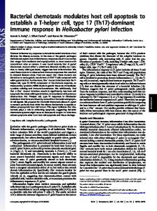
Figure 1: Moving bounding box ΩCell and level set domain ΩLS . essentially non-oscillatory (ENO) finite differences. Second-order derivatives are approximated using a standard second-order accurate central difference operator. Temporal integration is obtained using a second-order accurate explicit strong stability preserving (SSP) Runge-Kutta integrator. It is well known that an accurate numerical solution of (22) can only be obtained when a sufficiently dense mesh is used to resolve the radius of curvature of localised features of evolving curves. As we aim to simulate the migration of chemotaxing cells moving a distance of several cell diameters, the use of a fixed Cartesian mesh would be computationally expensive. To enhance the efficiency of the LS procedure we therefore have implemented a simple moving mesh strategy. Rather than cover the whole simulation domain with a fixed mesh, we instead only solve the level set equation (22) on a much smaller rectangular region, ΩLS , enclosing the cell, and we allow this box to move and change shape to follow the evolving cell. To do this, we proceed as follows: given the location of the curve Γh (t) we first enclose it within the bounding box (see Figure 1) ΩCell = [Iminx , Imaxx ] × [Iminy , Imaxy ]. The LS mesh ThLS covers the rectangular domain ΩLS = [Bminx , Bmaxx ] × [Bminy , Bmaxy ], using uniform mesh widths ∆x = ∆y. We next describe how we move the right-hand boundary Bmaxx as the other three boundaries are moved similarly. Given a user-specified tolerance εbox we compare Imaxx and Bmaxx . If the cell has moved sufficiently close to the right-hand boundary so that Imaxx > Bmaxx − εbox then we move the boundary such that Bmaxx = Bmaxx + ∆x. On the other hand, if the cell has moved to the left then it is possible that Imaxx < Bmaxx − 2εbox , in which case we move the boundary to the left such that Bmaxx = Bmaxx − ∆x. Otherwise, the right-hand boundary Bmaxx remains unaltered. After repeating this process for the other three sides we arrive at a new LS box and accompanying mesh. To complete the moving mesh process we re-initialise the level set function φ as a signed distance function over the new mesh.
9
5
Coupling the ALE-SFEM with the LSM
We next outline how we couple the ALE-SFEM to the LSM to solve problems on evolving curves that are dependent on the solution state on the surface. At the start of the time step FEM LS t = tn we have a finite element mesh Th,t and the level set mesh Th,t n n . The following steps n+1 are then carried to approximate the solution at time t = t . 1. UPDATE LS FUNCTION (a) Use the finite element solution ch to determine v(x) for x ∈ Γh (tn ). LS (b) For each grid-point (xi,j , yi,j ) ∈ Th,t n , find the closest node-point on the finite element FEM mesh Th,tn .
(c) For all LS grid points use zeroth-order extrapolation using the nearest-neighbour point to calculate v(x) and TOOLBOXLS to determine κ(x). (d) Use TOOLBOXLS to obtain an approximation of φ(x, tn+1 ). 2. UPDATE FE SOLUTION n+1 (a) Extract the contour ΓLS ) of the zero level set φ(x, tn+1 ). h (t
(b) Determine the finite element mesh at t = tn+1 . FEM – For each node xi of Th,t find the intersection of the straight line through xi n n in the direction u(xi , t ) with ΓLS h,tn+1 . FEM n+1 (c) Using the new mesh Th,t ,H n+1 , An+1 and update C n+1 by solving n+1 calculate M (21).
3. REGRID FEM MESH (if necessary) FEM (a) Replace Th,t n+1 by an equidistributed grid if either: FEM – The distance between any two adjacent points on Th,t n+1 is less than some userdefined tolerance. FEM – The distance between any two adjacent points on Th,t n+1 is greater than some user-defined tolerance.
(b) Use linear interpolation to define C n+1 at the equistributed mesh points. 4. MOVE LS BOX ΩLS (if necessary) (a) Decide whether or not we need to move ΩLS .
6 6.1
Numerical results Application to model problems
To investigate the convergence of the ALE-SFEM we consider the solution of the heat equation c˙ = ∆Γ c on the stationary unit circle. With c(θ, 0) = cos(θ) + cos(3θ) as the initial condition, the analytical solution c(θ, t) = e−t sin(θ) + e−9t sin(3θ). Figure 2 (a) shows the computed solution using N = 200 uniformly sized elements, where the approximate solution has been 10
200
−8 0
50
100
150
Node number
t = 0.2
t=1
200
2 −12
0
−14
1
1
−1 −2
−2
−1
0
c(x)
1
−10
150
log(||e||L2)
−2 100
Node number
2
50
2
0
c(x)
0
c(x)
−1
0 −2
−1
c(x)
−6
1
1
2
t = 0.1
2
t = 0.001
0
50
100
150
200
−8 0
Node number
50
100
150
200
Node number
(a)
−7
−6
−5 log(N
−4
−3
−2
)
−1
(b)
Figure 2: (a) Comparison of exact (−) and ALE-SFEM (×) solution of heat equation on a stationary unit circle. (b) Second-order convergence of ||e||L2 as the number of spatial elements N → ∞. plotted at every tenth grid node. We can see that the ALE-SFEM performs well for this value of N . To test the spatial rate of convergence of the ALE-SFEM, a suitably small time step is chosen such that the global error is dominated by its spatial component. Figure 2 (b) shows the error in the L2 norm at the final time T = 1. As expected, we observe second-order convergence with respect to the number of finite element mesh cells.
6.2
Application to cell migration problems
As mentioned earlier, we base our pseudopod-centred model on a system of reaction-diffusion equations that gives rise to a suitable spatio-temporal activator profile that can be used for the generation of pseudopods without the need for a driving external signal. The following set of equations are derived from a well established discrete model developed by Meinhardt [20]. The model describes the dynamic interaction between a local autocatalytic activator a, a rapidly distributed global inhibitor b and a local inhibitor c. Assuming that the cell boundary Γ(t) moves with velocity u, the equations take the form s(a2 /b + ba ) − ra a, (sc + c)(1 + sa a2 ) I ˙b + b∇Γ · u = Db ∆Γ b − rb b + rb a dx, |Γ(t)| Γ(t) c˙ + c∇Γ · u = Dc ∆Γ c + bc a − rc c.
a˙ + a∇Γ · u = Da ∆Γ a +
(23) (24) (25)
Here, ra , rb and rc denote decay rates of the local activator, global inhibitor and local inhibitor, respectively. The corresponding diffusion coefficients are Da , Db and Dc . In the non-linear 11
reaction term in the activator equation, sa is a saturation coefficient, sc is the Michaelis-Menten constant and ba is a basal production rate of the activator. The constant bc determines the growth of the local inhibitor c in the presence of the activator a. The effect of the external signal and random fluctuations are incorporated in the term s detailed below. It is well known that concentration differences of a few percent across a cell can be sufficient to allow chemotactic orientation [36]. An external signal and any external fluctuations are assumed to feed into the autocatalytic reaction term in the activator equation thus ensuring amplification of the external signal. In the original model of Meinhardt � � �� 2π|x − xc |Γ s(x, t) = ra 1 + dy cos (1 + dr RND), (26) |Γ(t)| where xc is the location on the cell membrane experiencing the highest concentration of chemoattractant and hence has the highest receptor occupancy. Here, dy and dr are positive parameters and 0 < RND < 1 is a uniformly distributed random number. A biological objection to using (26) is the need for a spatial cell-wide comparison of individual receptors to define xc and hence the direction towards the source of the chemoattractant. In addition, there is no justification for the use of a cosine function to describe the behaviour of the chemotactic signal term. Instead, we assume simple local ligand-receptor kinetics described by the reversible reaction k1 GGGGGG B C +RF G CR, k−1 where C denotes the local concentration of ligand (chemoattractant), R the concentration of membrane bound receptors and CR the concentration of the ligand-receptor bound complex. Assuming equilibrium conditions, the local receptor occupancy Ro =
CR C = , R + CR C + Kd
where Kd = k−1 /k1 is the disassociation constant. We therefore model the response to the external signal and the addition of random noise by the term noisy autocatalytic activation
s(x, t) = ra [
z }| { (1 + dr RND)
noisy chemotactic signal
z }| { + Ro (1 + dr RND)].
(27)
We have deliberately separated the two sources of noise to highlight the fact that they effect two different physical aspects of our model. The original Meinhardt model was proposed to generate the driving internal signal by amplification of external asymmetries. To our knowledge this signal has never been coupled with a mechanical model for the rearrangement of the cell cytoskeleton and this is what we propose next. We will assume that actin polymerization creates a protrusive force that pushes the cell membrane outwards in the normal direction. Recent detailed investigation of pseudopod formation suggests that this assumption is valid for cells migrating in the absence of external cues and in the presence of chemotactic gradients [5, 4]. We will assume that the rate of polymerization is proportional to the concentration of the local activator a. At rest, the cell experiences pressure from cortical tension, which maintains the spherical shape of the cell. Using a cortical shell-liquid drop model [8], the force generated by the cortical tension is assumed to act normal 12
to the cell membrane and depends on the local surface curvature κ. The protrusive velocity and the temporal cortical tension coefficient in (22) is given by v(x) = Kprot a(x),
and
dλ λ0 λ(A − A0 + dA/dt) = − βλ. dt A0 (λ + λ0 )
(28)
Here Kprot , λ0 and β are positive parameters and A0 is the initial prescribed area of the cell. The use of a time dependent cortical tension factor λ(t) controls the area of the evolving cell by allowing the area to possibly increase or decrease slightly from its initial value. Larger values of λ will increase the cortical tension which will eventually result in a decrease in the cell area. Conversely, by decreasing λ the cortical tension is weakened leading to an increase in cell area. There are many possible forms that a dynamic equation for λ could take but we have found through numerical experimentation that (28) works well and is robust to changes in the parameters involved. The equation describing the evolution of λ is approximated numerically using an explicit Euler method. From a biological viewpoint there are good reasons why the cell area is not exactly conserved. Experimental investigation of migrating cells in three dimensions suggest that, while the cell surface area can increase by up to 15%, the cell volume change is much more modest in the range of 1-2% [33]. Possible explanations for this behaviour are the exocytosis of internal membrane or the use of a reserve of folded surface membrane. 6.2.1
Migration in the absence of chemoattractant
Of fundamental importance to the current study of chemotaxis is the ability of the computational model to simulate cell motion in the absence of any chemoattractant. The following simulations were performed using the parameters found in Table 1 and a uniform time step ∆t = 0.1. The parameters in the Meinhardt model are identical to those used in his original paper [20]. The diffusion coefficients were chosen by experimentation with the restriction that Db � Da and Db � Dc to ensure that b acts as a global inhibitor. We have performed parameter studies which indicate that the simulations are robust with respect to changes in the values of the individual parameters, in the sense that these need to change by orders of magnitude to effect qualitatively different results. The mesh used with the ALE-SFEM has N = 200 elements and for the LSM we use a rectangular Cartesian mesh with ∆x = ∆y = 0.02. Simulations with finer grid densities indicate that the grid resolution used was sufficient to produce results to plotting accuracy. The initial conditions are assumed to be the homogeneous steady state corresponding to a circular cell of radius r = 0.1 located at the origin. Figure 3 shows the evolution of a simulated cell and plots of the corresponding local activator a, global inhibitor b and local inhibitor c. At time t = 1400 we can see the localisation of two activator peaks and their associated pseudopods. The arrows indicate growth of one of the pseudopods pulling the cell towards the right. At this time the second pseudopod is being retracted back into the cell body by cortical tension. We see the formation of two new “child” pseudopods around t = 1420 by splitting or bifurcation of their “parent” pseudopod. The two peaks in the activator profile at t = 1500 then move around the cell boundary in a traveling wave-like motion. Similar wave-like behaviour of shape regulating proteins has also been observed experimentally for migrating cells [34]. At t = 1650 we see that one of the peaks in the activator level eventually dominates and results in the formation of a “winning” pseudopod leading to a change in the cell’s direction. By t = 1700 we can see the retraction of a “losing” pseudopod and the splitting of the newly forming leading pseudopod. The simulated cycle of pseudopod splitting is remarkably similar to that observed across a wide range of cells 13
[1]. A global view of a typical migrating cell is shown in Figure 4 where we can see that the repeated cycle of the steps outlined above leads to persistent cell motion as the cell explores its local environment. Table 1:
Default parameter values for cell migration simulations.
Quantity
Symbol
Value
Decay rate of activator
ra
2 × 10⁻²
Basic production rate of activator
ba
1 × 10⁻¹
Saturation of activator autocatalysis
sa
5 × 10⁻⁴
Diffusion coefficient of activator
Da
4 × 10⁻⁷
Production & decay rate of global inhibitor
rb
3 × 10⁻²
Diffusion coefficient of global inhibitor
Db
4
Production rate of local inhibitor
bc
5 × 10⁻³
Decay rate of local inhibitor
rc
1.3 × 10⁻²
Diffusion coefficient of local inhibitor
Dc
2.8 × 10⁻⁶
Michaelis-Menten constant
sc
2 × 10⁻¹
Random fluctuation
dr
5 × 10⁻²
Kprot
1 × 10⁻⁵
Cortical tension factor
λ0
2 × 10⁻⁶
Cortical tension factor
β
1 × 10⁻⁶
Scaling of protrusive velocity
In the absence of any chemoattractant one would imagine that cells would move in random directions and exhibit a Brownian random walk. However, it has been observed that amoeboid cells move in random directions but with a high degree of persistence that keeps them moving in approximately the same direction [27, 5, 19]. It has been suggested that this search strategy greatly improves the cells chances of finding a target relative to performing a random walk [19]. Figure 5 shows the calculated trajectories of the centroids of 20 simulated cells. Each run was performed with a different initial seed in the random number generator used to introduce noise. The trajectories are compared with those of 10 wild type Dictyostelium cells [5]. We can see that the computational results qualitatively agree with the experimental data and that the cells exhibit a degree of persistency. To investigate the nature of the simulated random walks we also considered the evolution of the mean squared displacement (MSD) of a population of cells. We first calculate the squared displacement for each cell D2 (t) = |r(t) − r(0)|2 , where r(t) denotes the location of the cell centroid at time t. The mean squared displacement hD2 (t)i is then defined as the average of D2 (t) over the cell population. In Figure 6 we plot the MSD against time for a population of 1000 simulated cells. For an uncorrelated (Brownian) random walk the MSD should be a linear function of time which we can see does not fit the computed results close to t = 0. In fact, the simulated cells exhibit a persistent random walk which is well fitted by the distribution hD2 (t)i = 2v 2 [P t − P 2 (1 − e−t/P )],
(29)
where v is the speed of cell movement and P is the persistence time [5, 19]. For short time intervals the MSD varies quadratically in time indicating a straight line motion with constant 14
t = 1400
−0.5 −0.4 −0.3 −0.2 15
0.1
0.2
0.3
0.4
0.0
0.1
0.2
t = 1500
0.3
0.4
0.0
0.1
0.2
0.3
0.4
0
5
10
20
25
30
Interface location Activator level
0.0
t = 1420
0.0
0.2
0.4
0.6
0.8
1.0
0.0
0.2
0.4
0.6
0.8
1.0
0.0
0.2
0.4
0.6
0.8
1.0
Scaled Arc-length (arb)
t = 1650
−0.5 −0.4 −0.3 −0.2 15
0.1
0.2
0.3
0.4
0.0
0.1
0.2
t = 1700
0.3
0.4
0.0
0.1
0.2
0.3
0.4
0
5
10
20
25
30
Interface location Activator level
0.0
t = 1675
0.0
0.2
0.4
0.6
0.8
1.0
0.0
0.2
0.4
0.6
0.8
1.0
0.0
0.2
0.4
0.6
0.8
1.0
Scaled Arc-length (arb)
Figure 3: Simulated cell migration by pseudopod bifurcation in the absence of chemoattractant: (—) local activator, (− · −) global inhibitor and (− − −) local inhibitor.
15
Figure 4: Amoeboid-like migration in the absence of chemoattractant.
(a) Simulated
(b) Experimental
Figure 5: Trajectories of cell centroids in the absence of chemoattractant.
16
(a) Simulated
(b) Experimental 8000
2
< Displacement > ( µm )
6000
2
0.8
2
< Displacement > (arb)
1.0
0.6
0.4
4000
2000
0.2
0.0
0
0
1000
2000
3000
4000
5000
0
5
10
15
Time (min)
Time (arb)
Figure 6: Mean squared displacement of simulated and real cells in the absence of chemoattractant. velocity. For larger times the MSD varies linearly in time corresponding to a random walk. Figure 6 also compares the computational results with a plot of the MSD for Dictyostelium cells [5] where we can see that qualitative agreement with the experimental results is excellent.
6.2.2
Migration in the presence of chemoattractant
We next consider the migration of cells in the presence of a chemoattractant. In the first experiment we simulate cells moving upwards in a linear gradient of the concentration field. The simulations were performed by setting the concentration, C, at the bottom or back of the cell at y = −0.1 such that with Kd = 30, the receptor occupancy Rob = 0.15. The effect of different gradients was then tested by varying the signal strength Rof − Rob Rof − Rob = , σ≡ ∆y 0.2
(30)
where Rof denotes the receptor occupancy at the front or top of the cell. Figure 7 shows the simulation of migrating cells for various values of σ. In the absence of any signal, σ = 0, we observe persistent random migration as before. As the signal strength increases we find that cells are able to chemotax successfully and with increasing signal strength we observe better chemotactic efficiency with less dispersion of the cell trajectories. As a second experiment we simulate the chemotaxis of a single cell towards a point source of chemoattractant. Figure 8 (a) shows a cell migrating randomly before the introduction of the chemoattractant. Once the point source is introduced (b), we see that the cell quickly reorients itself and progresses accurately towards it. The movement towards the point source is observed to be driven by the biased generation of pseudopods at the front of the cell. At a later time the point source is moved (c), and we can see that the simulated cell successfully steers itself again by the biased generation of pseudopods at the front of the cell rather than by a sudden depolarisation of the cell. Similar behaviour is observed for real cells navigating in shallow chemotactic gradients [1]. Further detailed comparison between the predictions obatained using our computational model and experimental data can be found in [22].
17
σ=0
σ = 0.025
σ = 0.05
σ = 0.1
σ = 0.15
σ = 0.2
Figure 7: Trajectories of the centroids of cells migrating upwards in linear chemotactic gradients of varying strength.
(a)
(b)
(c)
Figure 8: (a) Random migration. (b) A point source of chemoattractant is introduced. (c) The point source is then relocated and the cell turns by the biased generation of pseudopods.
18
7
Conclusions
An ALE-SFEM has been introduced to solve reaction-diffusion equations on evolving curves. An advantage of the ALE formulation is its ability to accommodate the tangential movement of grid points and hence it could be used with methods that induce such motions to ensure good mesh quality [2]. Although we have concentrated in this paper on simulations in two dimensions, the ALE-SFEM method naturally extends to the solution of PDEs on evolving surfaces in three dimensions. To move the domain boundary a LSM was used. Although not presented here, this approach could be used to model cell deformation problems involving a change of topology such as cytokinesis where a single cell divides itself into two daughter cells [28]. The hybrid LS/ALESFEM requires the coupling of field variables defined on the finite element mesh to those on the Cartesian mesh used by the LSM. This coupling has been relatively easy to achieve and has worked well for the problems considered here but the extension of this procedure would certainly be more involved in higher dimensions. As an alternative we plan to investigate the use of a parameterised finite element approach for evolving the domain boundary for cell deformation problems that do not encounter a change of topology [2]. In this paper the model of Meinhardt has been used as the primary mechanism for the internal generation of signals for pseudopod formation. The model requires the introduction of a local inhibitor in addition to the standard two equation formulation involving a local activator and a global inhibitor. We have found through numerical experimentation that domain movement and shape changes play an important role in determining the spatio-temporal patterns obtained. It is well known that domain movement and shape changes can in fact regulate pattern formation [26] and hence further changes in the cell shape. We hypothesise that these geometrical feedback effects may obviate the necessity of a three component regulatory system [6]. From a biological viewpoint this would clearly be desirable by reducing the number of hypothetical biological entities. We are currently analysing the stability properties of the Meinhardt model under spatio-temporal domain perturbations to explore the necessity of the three equation formulation. Finally, the numerical simulations for cell migration problems provide compelling evidence of a pseudopod-centred view of eukaryotic chemotaxis. In the future we plan to use the developed computational framework to investigate other important cellular processes such as cell-cell signalling and the effect of substrate adhesions on cell movement and chemotaxis.
References [1] N. Andrew and R.H. Insall. Chemotaxis in shallow gradients is mediated independently of Ptdlns 3-kinase by biased choices between random protrusions. Nature Cell Biology, 9:193–200, 2007. [2] J.W. Barrett, H. Garcke, and R. N¨ urnberg. On the variational approximation of combined second and fourth order geometric evolution equations. SIAM J. Sci. Comp., 29:1006–1041, 2007. [3] D. Boffi and L. Gastaldi. Stability and geometric conservation laws for ALE formulations. Comp. Meth. Appl. Mech. Eng., 193:4717–4739, 2004.
19
[4] L. Bosgraaf and P.J.M. Van Haastert. Navigation of chemotactic cells by parallel signalling to pseudopod persistence and orientation. PLoS One., 4(8):e6842, 2009. [5] L. Bosgraaf and P.J.M. Van Haastert. The Ordered Extension of Pseudopodia by Amoeboid Cells in the Absence of External Cues. PLoS One., 4(4):e5253, 2009. [6] O. Brandman and T. Meyer. Feedback loops shape cellular signals in space and time. Science., 332:390–395, 2008. [7] D. Bray. Cell movements: from molecules to motility. Routledge, 2001. [8] J. Dai, H.P. Ting-Beall, R.M. Hochmuth, M.P. Sheetz, and M.A. Titus. Myosin I contributes to the generation of resting cortical tension. Biophys. J., 77(2):1168–1176, 1999. [9] K. Deckelnick, C.M Elliott, and V. Styles. Numerical diffusion induced grain boundary motion. Interfaces Free Boundaries, 3:393–414, 2001. [10] J. Donea, S.Giuliani, and J.P. Halleux. An Arbitrary Lagrangian-Eulerian finite element method for transient dynamic fluid-structure interactions. Comp. Meth. Appl. Mech. Engrg., 33:689–723, 1982. [11] G. Dziuk and C.M. Elliott. Eulerian finite element method for parabolic PDEs on implicit surfaces. Interfaces and Free Boundaries, 10:119–138, 2008. [12] G. Dzuik and C.M. Elliott. Finite elements on evolving surfaces. IMA Journal of Numerical Analysis, 27:262–292, 2007. [13] L. Formaggia and F. Nobile. A stability analysis for the arbitrary Lagrangian Eulerian formulation with finite elements. East-West Journal of Numerical Mathematics, 7:105–131, 1999. [14] L. Formaggia and F. Nobile. Stability analysis of second-order time accurate schemes for ALE-FEM. Comp. Meth. Appl. Mech. Eng., 193:4097–4116, 2004. [15] T.J.R. Hughes, W.K. Liu, and T.K. Zimmermann. Lagrangian-Eulerian finite element formulation for incompressible viscous flows. Comp. Meth. Appl. Mech. Engrg., 29:329– 349, 1981. [16] A.J. James and J. Lowengrub. A surfactant-conserving volume-of-fluid method for interfacial flows with insoluble surfactant. J. Comput. Phys., 201:685–722, 2004. [17] M. Lesoinne and C. Farhat. Geometric conservation laws for flow problems with moving boundaries and deformable meshes, and their impact on aeroelastic computations. Comput. Methods Appl. Mech. Engrg., 134:71–90., 1996. [18] C.H Leung and M. Berzins. A computational model for organism growth based on surface mesh generation. J. Comput. Phys., 188:75–99, 2003. [19] L. Li, S.F. Nørrelykke, and E.C. Cox. Persistent Cell Motion in the Absence of External Signals: A Search Strategy for Eukaryotic Cells. PLoS One., 3(5):e2093, 2008. [20] H. Meinhardt. Orientation of chemotactic cells and growth cones: models and mechanisms. Journal of Cell Science, 112:2867–2874, 1999. 20
[21] I.M. Mitchell. The Flexible, Extensible and Efficient Toolbox of Level Set Methods. J. Sci. Comput., 35:300–329, 2008. [22] M. Neilson, J.A. Mackenzie, S.D. Webb, P.J.M. Van Haastert, D. Veltman, and R.H. Insall. A simple pseudopod-based model efficiently explains multiple aspects of cell behaviour during chemotaxis, 2010. In preparation. [23] S.I. Nishimura, M. Ueda, and M. Sasai. Cortical Factor Feedback Model for Cellular Locomotion and Cytofusion. PLoS Computational Biology., 5(3):e10000310, 2009. [24] F. Nobile. Numerical approximation of fluid-structure interaction problems with application ´ to haemodynamics. PhD thesis, Department of Mathematics, Ecole Polytechnique F´ed´erale de Lausanne, 2001. [25] S. Osher and J.A. Sethian. Fronts propagating with curvature-dependent speed: algorithms based on Hamilton-Jacobi formulations. J. Comput. Phys., 79(1):12–49, 1988. [26] R. Plaza, F. Sanchez-Garduno, P. Padilla, R.A. Barrio, and P.K. Maini. The effect of growth and curvature on pattern formation. J. Dyn. Differ. Equ., 16(4):1093–1121, 2004. [27] M.J. Potel and S.A. Mackay. Preaggregative cell motion in Dictyostelium. J. Cell Sci., 36:281–309, 1979. [28] E.M. Reichl, J.C. Effer, and D.N. Robinson. The stress and strains of cytokinesis. Trends Cell Biol., 15(4):200–206, 2005. [29] S.J. Ruuth and B. Merriman. A Simple Embedding Method for Solving Partial Differential Equations on Surfaces. J. Comput. Phys., 227(3):1943–1961, 2008. [30] J. Satulovsky, R. Lui, and Y.L. Wang. Exploring the control circuit of cell migration by mathematical modeling. Biophys J., 94:3671–3683, 2008. [31] A. St´ephanou, M. Chaplain, and P. Tracqui. A mathematical model for the dynamics of large membrane deformations of isolated fibroblasts. Bull. Math. Biol., 66:1119–1154, 2004. [32] A. St´ephanou, E. Mylona, M. Chaplain, and P. Tracqui. A computational model of cell migration coupling the growth of focal adhesions with oscillatory protrusions. J. Theor. Biol., 325:701–716, 2008. [33] D. Traynor and R.R. Kay. Possible roles of the endocytic cycle in cell motility. J. Cell Sci., 120:2318–2327, 2007. [34] O.D. Weiner, W.A. Marganski, L.F. Wu, S.J. Altschuler, and M.W. Kirschner. An actinbased wave generator organizes cell motility. PLoS Biology., 5:e221, 2007. [35] L. Yang, J.C. Effler, B.L. Kutscher, S.E. Sullivan, D.N. Robinson, and P. A. Iglesias. Modeling cellular deformations using the level set formalism. BMC Systems Biology, 2:68, 2008. [36] S.H. Zigmond. Ability of polymorphonuclear leukocytes to orient in gradients of chemotactic factors. J. Cell Biol., 75:606–617, 1977.
21