The model contains neutral silanes, silylenes, silenes and silyl radicals as well as silyl and silylene anions. Reaction rates were estimated from available data.
J. Phys. D: Appl. Phys. 33 (2000) 2731–2746. Printed in the UK
PII: S0022-3727(00)14861-2
Modelling of silicon hydride clustering in a low-pressure silane plasma U V Bhandarkar†, M T Swihart‡, S L Girshick† and U R Kortshagen† † Department of Mechanical Engineering, University of Minnesota, 111 Church St SE, Minneapolis, MN 55455, USA ‡ Department of Chemical Engineering, State University of New York, Buffalo, NY 14260-4200, USA Received 21 June 2000 Abstract. A new silicon hydride clustering model was developed to study the nucleation of particles in a low-temperature silane plasma. The model contains neutral silanes, silylenes, silenes and silyl radicals as well as silyl and silylene anions. Reaction rates were estimated from available data. Simulations were carried out for typical discharge parameters in a capacitive plasma. It was shown that the main pathway leading to silicon hydride clustering was governed by anion–neutral reactions. SiH2 radical insertion was found to be important only in the initial stages of clustering, whereas electron-induced dissociations were seen to lead to dehydrogenation. Increased ion density (radiofrequency power density) leads to faster clustering due to increased formation of reactive radicals. (Some figures in this article are in colour only in the electronic version; see www.iop.org)
1. Introduction
Plasma enhanced chemical vapour deposition (PECVD) is widely used in the semiconductor industry to deposit layers of thin silicon films using silane or disilane precursor gases. This process suffers from gas phase nucleation of nanometresized particles. At present these particles are too small to be of any concern. However, according to the National Technology Roadmap for Semiconductors [1], device sizes will drop to such an extent in the future that by the year 2012, particles of diameter 16 nm will be one-third the feature sizes, thus deeming them ‘killer’ particles. Apart from this harmful aspect, nanoparticles of the desired chemical composition and size may be useful for their electro-optical and mechanical properties [2–5]. Amorphous Si:H films deposited under conditions at which nanometric particles can be observed in the films have also been shown to increase the performance of solar cells [6, 7]. An understanding of particle nucleation and growth will thus prove useful in suggesting methods not only to eliminate ‘bad’ particles but also to generate ‘good’ particles. An insight into the steps in particle generation can be obtained from the experiments performed by Bouchoule and co-workers [8–12]. The authors suggest that particles in a silane plasma grow in three steps: initial nucleation followed by coagulation of small particles followed by the growth of bigger particles due to surface deposition of radicals. The authors also noticed a marked decrease in electron concentration during the coagulation phase. A corresponding increase in the electron temperature from 2 to 8 eV to maintain sufficient ionization was also observed. Plasma parameters 0022-3727/00/212731+16$30.00
© 2000 IOP Publishing Ltd
thus changed drastically during particle growth. Models studying particle nucleation and growth in a plasma will have to account self consistently for the coupling between particle growth and changes of the plasma properties. In this paper we try to shed some light on the clustering process which leads to the nucleation of particles. The pathway for silicon hydride clustering in silane plasmas has been a contentious issue. Watanabe and co-workers [13–17] inferred from their experiments that short lifetime radicals like SiH2 play an important role in particle nucleation. By conducting experiments at various radio frequencies (RF) and observing the SiH2 and particle density profiles, the authors concluded that short lifetime radicals are involved in many steps of the polymerization chain. From these observations the authors inferred that clustering proceeds by SiH2 insertion reactions. However, other authors favour an anionic pathway over the neutral pathway proposed by Watanabe and co-workers. Since it is well known that anions in a plasma are trapped by the ambipolar potential, they are generally believed to be important in clustering due to their longer lifetime in the plasma. Hollenstein and coworkers [18, 19] studied the role of anions by measuring mass spectra and conducting partial depth modulation experiments on capacitive plasmas. The authors observed particle formation as long as the anions remained trapped in the plasma. However, no correlation was found between particle generation and neutral clusters. In fact, anionic clusters were found in greater sizes and concentration than neutral clusters. Positive clusters were seen to be restricted to clusters having six Si atoms or less. Positive ions were thus expected to play a negligible role in the cluster formation process, a 2731
U V Bhandarkar et al
fact also noted by other researchers [20, 21]. Based on their observations, Hollenstein and co-workers suggested a cluster formation pathway dominated by anion–neutral reactions. Apart from these reaction pathways for cluster formation, some authors also proposed that vibrationally excited species play an important role by providing energy for endothermic reactions [22] and by augmenting the dissociation process of silane [23]. 2. Model description
Our model for the clustering process in silane plasmas is based on the mechanism developed by Swihart and Girshick [24] and Girshick et al [25] for the clustering of neutral species in atmospheric pressure thermal CVD of silicon from silane. In this model, a group additivity scheme was used to predict the thermochemical properties of large silicon hydride clusters. Such a method has already been successfully implemented in predicting the thermochemistry of hydrocarbons [26]. For the silicon hydride clusters, twenty-six groups were defined and data were used from the ab initio calculations of Katzer et al [27]. The silicon hydrides were classified as silanes, silenes (the molecular formulae of these were suffixed with the letter A) and silylenes (molecular formulae suffixed with the letter B). The silanes are akin to alkanes in hydrocarbons. Silenes have a double bond between two silicon atoms and are physically similar to the double-bonded alkenes in hydrocarbons. The silylenes are isomers of silenes with two non-bonding electrons. A base reaction mechanism was incorporated from Ho et al [28] for neutral species containing one or two silicon atoms. For reactions between larger silicon hydrides, five reaction classes were defined [24]. The important premise used in determining the reaction rates was the fact that silylene insertions into Si–H and H–H bonds are known to be barrierless. The reverse elimination reactions were therefore assumed to have activation energies equal to the enthalpy of reaction. This scheme inherently takes care of structural differences of the reaction partners, i.e. whether cyclic or acyclic species are involved. Ring formation reactions were included as a separate class of reactions and equated to a reaction where a divalent Si atom inserts into an Si–H bond in the same molecule. The maximum cluster size considered in this mechanism was ten silicon atoms. All reactions leading to clusters with more than ten Si atoms were considered irreversible. These clusters with more than ten Si atoms were classified as ‘particles’. We have used the same approach in our model which is described below. The important reactions in our plasma model are the electron dissociation and attachment reactions, anion–neutral reactions, reactions involving silyl and H radicals and neutralization reactions. The silyl radicals are mono-radicals of the corresponding silanes and analogs of the alkyl radicals in hydrocarbons. The thermochemical data of the silyls have been obtained by the same group additivity method as used in [24]. The thermochemical data for silyls are given in table 1. Electrons are treated as a separate species having a temperature different from the surrounding gas species. The rate constants of electron-induced reactions depend on the electron temperature. Determining such a rate constant 2732
involves an integration of the energy dependent collision frequency over the electron energy distribution function (EEDF). In our current study we assume a Maxwellian EEDF although it should be noted that the EEDF often deviates significantly from a Maxwellian. By obtaining the rate constants at different electron temperatures, we can fit Arrhenius rate constant parameters to the data. Cross section data are available for the dissociation, ionization and attachment reactions of silane [29–35] and in some cases for disilane [36]. Reaction rate constants have been calculated in [37] for the following electron dissociation reactions of silane and hydrogen: SiH4 + e → SiH3 + H + e
(1)
SiH4 + e → SiH2 + 2H + e
(2)
H2 + e → 2H + e.
(3)
and The dissociation of silane is assumed to have a branching ratio of 1:5 in favour of SiH2 [35]. Since it is known that disilane has a dissociation cross section which is approximately twice that of silane [38], the pre-exponential for the electron dissociation of disilane is assumed to be twice that for silane. Disilane dissociates predominantly as follows [35] Si2 H6 + e → SiH3 + SiH2 + H + e.
(4)
We assume that acyclic silanes with dangling SiH3 groups are likely to dissociate by losing an SiH3 radical, similar to the dissociation of disilane. These dissociation reactions are thus assumed to lead to the loss of an SiH3 radical from the parent silane, for example, Si3 H8 + e → Si2 H4 B + SiH3 + H + e.
(5)
The pre-exponentials of the rate constants for these reactions are estimated by counting the number of dangling SiH3 groups in the cluster and multiplying the preexponential of the rate constant for disilane dissociation by this number. All other silicon hydrides are assumed to dissociate by elimination of a hydrogen atom, and the preexponential of the rate constant for such reactions is scaled on the basis of the number of hydrogen atoms in the cluster as compared to that in silane. The Arrhenius expressions for the rates of all the above reactions are noted in table 2. Reaction rate parameters for dissociative attachment to silane are calculated as mentioned earlier, using the corresponding cross section data obtained from Bordage [39]. These dissociative attachment reactions lead to the − formation of SiH− 3 and SiH2 anions. Reaction rates for electron attachment to larger silicon hydrides are calculated using the formula [35] −1
kA ≈ 5.3 × 10⁻¹⁰ Te 2 (eV)P (Torr)
300 (cm3 s−1 ) T (K)
(6)
where Te is the electron temperature, T is the gas temperature and P is the pressure. We assume nondissociative attachment when considering silyls and silylenes and dissociative attachment when considering silanes. This favours the formation of anionic radicals [18]. The formation
Modelling of silicon hydride clustering Table 1. Thermochemical data for silyl radicals.
Cp
Speciesa
�Hfo 298
So 298
300
400
500
600
800
1000
1500
Si3 H7 Si3 H5 Si4 H9 Si4 H7 Si5 H11 Si5 H9 Si5 H7 Si6 H13 Si6 H11 Si6 H9 Si6 H7 Si6 H5 Si7 H15 Si7 H13 Si7 H11 Si7 H9 Si7 H7 Si8 H17 Si8 H15 Si8 H13 Si8 H11 Si8 H9 Si8 H7 Si9 H19 Si9 H17 Si9 H15 Si9 H13 Si9 H11 Si9 H9 Si10 H21 Si10 H19 Si10 H17 Si10 H15 Si10 H13 Si10 H11 Si10 H9
63.60 98.94 70.25 88.78 81.21 86.64 114.84 87.86 90.77 119.31 151.80 184.54 94.51 97.42 117.17 141.89 174.38 105.77 105.56 115.03 116.21 164.54 177.72 112.15 112.21 119.16 120.10 162.16 175.11 118.77 120.65 123.29 118.97 136.25 172.97 198.23
85.56 75.67 101.51 87.24 115.23 99.93 87.81 131.18 111.60 104.76 94.95 84.84 147.13 127.55 117.45 106.22 96.41 160.59 141.80 130.14 112.89 107.19 92.80 177.86 157.75 141.81 125.20 120.52 106.28 192.75 171.80 153.48 132.20 127.34 118.97 106.46
26.86 23.21 35.58 31.75 45.39 40.48 36.22 54.11 50.22 45.35 41.87 38.20 62.83 58.94 54.08 50.22 46.74 72.60 68.32 62.81 58.15 55.10 50.89 81.12 77.04 72.55 66.87 62.81 58.55 90.08 86.44 82.29 78.24 70.69 67.28 64.50
31.54 26.90 41.83 37.22 53.02 47.67 42.40 63.31 58.91 53.13 48.44 43.68 73.60 69.20 63.58 58.69 54.00 84.91 79.98 74.03 68.58 64.18 58.98 94.94 90.27 85.27 78.72 73.53 68.36 105.37 101.18 96.51 91.57 83.45 78.81 74.92
35.19 29.55 46.67 41.17 58.94 52.83 46.64 70.42 65.21 58.51 52.70 46.82 81.90 76.69 70.17 64.25 58.44 94.25 88.57 81.83 75.49 69.94 63.78 105.52 100.05 94.21 86.80 80.53 74.40 117.13 112.03 106.59 100.76 91.80 86.06 81.13
38.17 31.62 50.64 44.24 63.73 56.88 49.85 76.20 70.28 62.66 55.89 49.10 88.67 82.75 75.30 68.49 61.72 101.83 95.52 87.94 80.79 74.24 67.21 114.13 107.99 101.34 93.10 85.79 78.81 126.70 120.84 114.74 108.18 98.14 91.45 85.60
42.78 34.79 56.72 48.88 71.12 62.96 54.66 85.06 77.75 68.83 60.67 52.50 99.00 91.69 82.91 74.75 66.59 113.43 105.85 96.99 88.65 80.64 72.38 127.27 119.79 111.78 102.41 93.69 85.44 141.28 134.01 126.57 118.85 107.60 99.52 92.35
46.04 37.04 60.99 52.12 76.27 67.18 57.97 91.22 82.86 73.09 63.96 54.84 106.17 97.81 88.15 79.05 69.92 121.45 112.92 103.21 93.99 84.98 75.81 136.35 127.87 118.89 108.66 99.03 89.87 151.35 143.00 134.57 125.91 113.98 104.93 96.80
50.54 40.16 66.88 56.57 83.36 72.97 62.49 99.70 89.73 78.91 68.45 58.01 116.04 106.07 95.31 84.88 74.42 132.51 122.47 111.71 101.24 90.84 80.39 148.85 138.81 128.47 116.99 106.23 95.78 165.20 155.21 145.23 135.10 122.59 112.18 102.75
a Enthalpies are in kcal mol−1 . Entropies and heat capacities are in cal mol−1 K−1 ). Enthalpy and entropy are at standard conditions of 298.15 K, 1 bar.
of negative ions of silanes may not be possible since ab initio calculations show that silanes have a negative electron affinity [40]. The H radical formed in equation (3) reacts with silane leading to hydrogen abstraction H + SiH4 � H2 + SiH3 .
We thus write the following reactions Sin+j H2m+2k−2 � Sin H2m−1 + Sij H2k−1 Sin H2m−1 + Sij H2k−1 → Sin+j H2m+2k−2
(n + j � 10) (8) (n + j � 11). (9)
(7)
The reaction rate constant for this reaction is available in [37]. This hydrogen abstraction reaction is possible for all larger silicon hydrides, and as a first estimate we use the same rate parameters for these reactions as for reaction (7). These rate parameters are noted in table 2. Both the electron dissociation of silanes and hydrogen abstraction from silanes create the highly reactive silyl species. The recombination reaction between two silyls is assumed to be barrierless. Following the same principle used for silylene insertion reactions in the neutral mechanism, we calculate the activation energy of the reverse reaction from the enthalpy of the reaction. Any reaction leading to a cluster with more than ten silicon atoms is considered irreversible.
2.1. Anions Anions are formed from neutral clusters via attachment reactions discussed above. Unfortunately, there is little information about the thermochemical properties of anions. However, since the anions differ from the corresponding neutrals by an extra electron, we can assume that the presence of the electron will not add any significant vibrational or other excitation modes to the neutral and hence the specific heat of the anion can be assumed to be close to that of the neutral. The enthalpy of the anion will be smaller than that of the neutral by an amount equal to the electron affinity of the neutral, since the neutral loses this energy by attaching the electron. The entropy of the anion is assumed to be equal to that of the neutral. Electron affinity data for all silicon 2733
U V Bhandarkar et al Table 2. Reaction mechanism. Forward rate constants are expressed in the form kf = AT β exp(−Ea /RT ).
Reaction Base mechanism 1. SiH4 (+M) � SiH2 + H2 (+M) High-pressure limit Low-pressure limit 2. Si2 H6 (+M) � SiH4 + SiH2 (+M) High-pressure limit Low-pressure limit 3. Si2 H6 (+M) � H2 + Si2 H4 B (+M) High-pressure limit Low-pressure limit 4. Si3 H8 (+M) � SiH2 + Si2 H6 (+M) High-pressure limit Low-pressure limit 5. Si3 H8 (+M) � SiH4 + Si2 H4 B (+M) High-pressure limit Low-pressure limit 6. Si2 H4 B (+M) � Si2 H4 A (+M) High-pressure limit Low-pressure limit 7. Si2 H4 B + H2 � SiH2 + SiH4 Reverse 8. Si2 H4 B + SiH4 � Si2 H6 + SiH2 Reverse 9. Si2 H4 B (+M) � Si + SiH4 (+M) High-pressure limit Low-pressure limit 10. Si + Si2 H6 � SiH2 + Si2 H4 B 11. SiH2 + M � Si + H2 + M 12. H + SiH4 � H2 + SiH3 13. SiH2 + SiH2 � Si2 H2 + H2 14. H + Si2 H6 � SiH4 + SiH3 15. H + Si2 H6 � Si2 H5 + H2 16. SiH3 + SiH3 � SiH2 + SiH4 17. SiH4 + SiH3 � Si2 H5 + H2 18. SiH4 + SiH � Si2 H3 + H2 19. SiH2 + H � SiH + H2 20. SiH3 (+M) � SiH + H2 (+ M) High-pressure limit Low-pressure limit 21. Si2 H4 B (+M) � Si + SiH4 (+ M) High-pressure limit Low-pressure limit 22. SiH + SiH4 � Si2 H4 B + H 23. Si + Si2 H6 � SiH2 + Si2 H4 B 24. SiH3 + H � SiH2 + H2 Hydrogen elimination (33 reactions) 25. Sin H2m � Sin H2(m−1) B + H2
2734
A (cm3 s−1 mol−1 )
β
Ea (cal mol−1 )
3.12 × 10⁹ 5.21 × 1029
1.7 −3.54
54 710 57 550
1.81 × 10¹⁰ 5.09 × 1053
1.7 −10.37
50 203 56 034
9.09 × 10⁹ 1.94 × 1044
1.8 −7.77
54 197 59 023
6.97 × 10¹² 1.73 × 1069
1.0 −15.07
52 677 60 491
3.73 × 10¹² 4.36 × 1076
1.0 −17.26
50 850 59 303
2.54 × 10¹³ 1.1 × 1033 9.41 × 10¹³ 9.43 × 10¹⁰ 1.73 × 10¹⁴ 2.65 × 10¹⁵
−0.2 −5.76 0.0 1.1 0.4 0.1
5 381 9 152 4 092.3 5 790.3 8 898.7 8 473.4
2.42 × 10¹³ 2.35 × 1042 1.3 × 10¹⁵ 9.1 × 10²⁰ 1.47 × 10⁸ 6.51 × 10¹⁴ 6.69 × 10¹¹ 1.30 × 10¹² 1.80 × 10¹³ 1.77 × 10¹² 1.45 × 10¹² 1.39 × 10¹³
0.54 −7.42 0.0 1.76 1.9 0.0 0.0 0.0 0.0 0.0 0.0 0.0
57 548 60 957 12 600 38 241 2 190 0.0 0.0 0.0 0.0 4 400 2 000 0.0
4.47 × 10¹⁴ 1.98 × 1026
−0.6 −3.1
44 698 44 770
1.42 × 10¹³ 2.35 × 1042 3.00 × 10¹⁴ 1.3 × 10¹⁵ 1.5 × 10¹³
0.5 −7.4 0.0 0.0 0.0
57 548 60 958 9 012 12 600 2 500
Reference
Comment
[28] [28] [28] [28] [28] [28]
[28] [28] [28] [28] [28]
[28] [28] [37] [37] [37] [37] [37] [37] [37] [37] [37] [37]
[37] [37] [37]
2.0 × 10¹⁵
0.0
�Hrxn, 500 K
[24]
Silylene elimination from silanes (149 reactions) 2.0 × 10¹⁵ 26. Sin H2m � Sij H2k B + Sin−j H2(m−k)
0.0
�Hrxn, 500 K
[24]
Silylene elimination from silenes (163 reactions) 27. Sin H2m A � Sij H2k B + Sin−j H2(m−k) A 2.0 × 10¹⁵
0.0
�Hrxn, 500 K
[24]
Silylene to silene isomerization (33 reactions) 28. Sin H2m B � Sin H2m A
1.0 × 10¹³
0.0
Ring opening/formation (28 reactions) 29. Sin H2m � Sin H2m B (n � 3)
2.0 × 10¹⁵
0.0
Silyl formation by H radical (36 reactions) 30. H + Sin H2m � Sin H2m−1 + H2
1.47 × 10⁸
1.9
2 190
Silyl additions to give higher silanes (113 reactions) 31. Sin H2m−1 + Sij H2k−1 � Sin+j H2m+2k−2 2.0 × 10¹⁵
0.0
�Hrxn,500 K
7 500 �Hrxn, 500 K
[24] [24] [37] est.
Modelling of silicon hydride clustering Table 2. (Continued)
Reaction
A (cm3 s−1 mol−1 )
Irreversible particle formation (807 reactions) 32. Sin H2m + Sij H2k B → particle 1.6 × 10¹³ (n + j � 11) 33. Sin H2m A + Sij H2k B → particle 1.6 × 10¹³ (n + j � 11) 34. Sin H2m−1 + Sij H2k−1 → particle 1.6 × 10¹³ (n + j � 11) Electron dissociation of silane 35. SiH4 + e → SiH3 + H + e 36. SiH4 + e → SiH2 + 2H + e
1.1 × 10²¹ 5.4 × 10²¹
Electron dissociation of hydrogen 37. H2 + e → 2H + e
1.02 × 10²¹
Electron dissociation of higher silanes (38 reactions) 38. Straight chain silane + e (NSiH3 )10.8 × 10²¹a → silyl + silylene + H + e e.g. Si3 H8 + e → Si2 H4 B + SiH3 + H + e 39. Cyclic silane + e → H + silyl + e (NH /4)5.4 × 1021b
Ea (cal mol−1 )
β
Reference
0.5
0.0
[24]
0.5
0.0
[24]
0.5
0.0
Comment
est.
−1.0 −1.0
245 430 245 430
[37] [37]
0.0
238 356
[37]
−1.0
245 430
est.
−1.0
245 430
est.
Dissociative attachment to silane by electrons 40. SiH4 + e → SiH− 2.269 × 10²³ 3 +H 41. SiH4 + e → SiH− + 2H 2.269 × 10²³ 2
−1.627 −1.627
190 540 190 540
calc. calc.
Electron attachment to silicon hydrides (196 reactions) 42. Sin Hm + e → Sin H− 1.55 × 10¹³ m
0.0
0.0
Negative silylene with silane (209 reactions) Langevin × 0.1 43. Sin H2m B− + Sij H2k � Sin+j H2m+2k−2 B− + H2
calc.
Negative silylene with silylene (192 reactions) 44. Sin H2m B− + Sij H2k B Langevin × 0.1 � Sin+j H2m+2k−2 B− + H2 Charge exchange between negative silylene and silyl (1330 reactions) 45. Sin H2m B− + Sij H2k−1 Langevin × 0.1 � Sin H2m B + Sij H− 2k−1
calc. calc.
Negative silyl with silane (570 reactions) Langevin × 0.1 46. Sin H− 2m−1 + Sij H2k � Sin+j H− 2m+2k−3 + H2 Negative silyl with silylene (531 reactions) Langevin × 0.1 47. Sin H− 2m−1 + Sij H2k B � Sin+j H− 2m+2k−3 + H2 Negative silyl with silyl (217 reactions) 48. Sin H− 2m−1 + Sij H2k−1 � Sin+j H2m+2k−4 B− + H2
Langevin × 0.1
Neutralization of anions (196 reactions) + 49. Sin H− m + SiH3 → Sin Hm +SiH3
1.74 × 10¹⁶
a b
calc.
calc. calc.
calc.
0.0
0.0
calc.
NSiH3 is the number of dangling SiH3 groups in the cluster. NH is the number of hydrogen atoms in the cluster.
hydride clusters with up to seven silicon atoms have been calculated using ab initio methods by Swihart [40], and our model includes these data. These electron affinities are given in table 3 [40]. Swihart [40] has fit the calculated electron affinity data of acyclic silicon hydrides to curves which can be extrapolated to calculate the electron affinities of clusters having eight or more Si atoms. For reactions involving anions, we consider both clustering as well as neutralization reactions. Extrapolating from known ion–neutral reactions of small silicon hydrides [35], we consider the following reactions Sin H2m B− + Sij H2k � Sin+j H2m+2k−2 B− + H2
(10)
Sin H2m B− + Sij H2k B � Sin+j H2m+2k−2 B− + H2
(11)
− Sin H2m B− + Sij H2k−1 � Sin H2m B + Sij H2k−1
(12)
− − + Sij H2k � Sin+j H2m+2k−3 + H2 Sin H2m−1
(13)
− Sin H2m−1
(14)
+ Sij H2k B �
− Sin+j H2m+2k−3
+ H2
− + Sij H2k−1 � Sin+j H2m+2k−4 B− + H2 . Sin H2m−1
(15)
Usually, reaction rates for these reactions are calculated using Langevin rates [35], but we have used Langevin rate constants reduced by an order of magnitude, as Langevin rates are known to overestimate the actual rates by an order 2735
U V Bhandarkar et al Table 3. Electron affinities.
Species
Calc. [40]
Si 1.32 SiH 1.25 SiH2 1.16 SiH3 1.41 SiH4 −1.30 Si2 2.09 SiHSi 2.17 SiSiH 2.18 H2 SiSiH2 1.31 H3 SiSiH 1.67 H3 SiSiH2 1.82 H3 SiSiH3 −0.43 1-Si3 H7 1.96 2-Si3 H7 2.12 Si3 H6 A 1.51 1-Si3 H6 B 1.84 2-Si3 H6 B 2.07 2.20 Si3 H5 Si3 H4 A 1.61 Si3 H4 B 2.07 1-i-Si4 H9 2.14 2-i-Si4 H9 2.36 1-n-Si4 H9 2.11 2-n-Si4 H9 2.26
Exp. [35]
Species
Calc. [40]
Species
Calc. [40]
1.39 1.28 1.12 1.41
1-i-Si4 H8 A 1-n-Si4 H8 A 2-n-Si4 H8 A 1-i-Si4 H8 B 1-n-Si4 H8 B 2-n-Si4 H8 B Si4 H7 Si4 H6 A Si4 H6 B Si5 H11 1-Si5 H10 A 2-Si5 H10 A Si5 H10 B Si5 H9 Si5 H8 A Si5 H8 B Si5 H7 Si5 H6 A Si5 H6 B 1-Si6 H13 2-Si6 H13 Si6 H12 A Si6 H12 B Si6 H11
1.68 1.64 1.68 1.96 1.94 2.18 2.15 1.43 2.10 2.24 1.72 1.80 2.08 2.34 1.62 2.22 2.56 1.97 1.54 2.25 2.42 1.80 2.14 2.38
Si6 H10 A Si6 H10 B Si6 H9 Si6 H8 A Si6 H8 B Si6 H7 Si6 H6 A Si6 H6 B 1-Si7 H15 2-Si7 H15 Si7 H14 A Si7 H14 B Si7 H13 Si7 H12 A Si7 H12 B Si7 H11 Si7 H10 A Si7 H10 B Si7 H9 Si7 H8 A Si7 H8 B Si7 H7 Si7 H6 A Si7 H6 B
1.77 2.30 2.41 1.96 1.93 2.50 1.88 1.37 2.33 2.56 1.89 2.16 2.57 1.89 2.13 2.51 1.63 2.06 2.56 2.28 1.76 2.52 1.90 1.88
2.20
of magnitude or two. Langevin rate constants (kL ) are calculated as follows [35], �
π kL = e �o
�1/2 �
α mr
�1/2 .
(16)
In this equation α refers to the polarizability of the neutral atom or molecule (in Å3 ) and mr is the reduced mass (in amu) of the two reacting species. The polarizability is given by a scaling law [35] α(Sin H2n+1 ) ≈ α(SiH4 )[1 + 0.8(n − 1)] = 4.62(0.2 + 0.8n)(Å3 )
(17)
where the polarizability of SiH4 of 4.62 (Å3 ) is used. Since in the above reactions both directions represent ion–molecule reactions, it is not clear a priori which direction has to be taken as the forward direction. We have assumed that the exothermic reaction is the forward direction always. In this way we ensure that the reaction rate constants for both forward and backward reactions are smaller than the Langevin rate. This is physically reasonable since the Langevin rate is an upper bound for the actual reaction rate. For the neutralization reactions, we assume that SiH+3 is the most abundant positive ion [19], and we neglect larger positive ions for simplicity. Based on available information [30, 41], any reaction involving an anion with fewer than four Si atoms is assumed to result in charge exchange, whereas reactions with larger anions lead to a larger neutral cluster. However, our calculations of the change in free energy show that clustering is the favourable reaction in all cases. The reaction leading to charge exchange leads to a large positive change in free energy and thus should be unfavourable. Thus all the neutralization reactions are written as follows − Sin Hm + SiH+3 → Sin+1 Hm+3 .
2736
(18)
The reaction rate coefficient for these reactions is calculated from [35]. Although these reactions have a weak dependence on the gas temperature and the size of reaction partners, we currently are using a constant reaction rate coefficient (kn ) of 1.74 × 1016 cm3 s−1 for these reactions, representative of a gas temperature of 500 K. We expect variations due to size and temperature to be within a factor of two [42]. Electron detachment from anions is currently neglected. 3. Solution procedure
The reaction mechanism consists of more than 300 species and 5500 reactions (with more than 3000 reversible reactions) and is solved for a zero-dimensional system using a modified version of SENKIN [43]. We currently are not able to treat transient gas heating or different temperatures for different species due to exothermic reactions. Instead, we consider the gas temperature as constant. This code uses a system of rate equations for the molar concentrations of the species involved. We have modified the code by introducing an additional loss term into the balance equations to account for diffusion losses. The rate equations have the general form, dXk = S˙k dt
(19)
where Xk is the molar concentration of species k and S˙k is a source or sink term, which is split as follows ˙ + SkD ˙ . S˙k = SkR
(20)
˙ is the source/sink term due to reactions and has the form SkR ˙ = SkR
I � i=1
� � � K K � � �� �� � (νki − νki ) kf i [Xk ]νki − kri [Xk ]νki (21) j =1
j =1
Modelling of silicon hydride clustering
where we sum over all reactions from i = 1 to I . The terms � �� and νki represent the stoichiometric coefficients of the νki species k in the respective reactions. The forward and reverse rate constants of the reaction i are represented by kf i and kri respectively. The superscript K represents the total number of species. The concentration of the species k is represented by [Xk ]. ˙ is simply the The diffusion loss term represented by SkD product of the diffusion frequency νDk for the species k and its concentration ˙ = νDk [Xk ]. (22) SkD The diffusion frequency is given by Dk /'2 where Dk is the diffusion coefficient of species k in the surrounding gas and ' is a typical diffusion length. With the exception of the discussion of the impact of the sticking probability at the end of the paper, we assume that the species stick to the walls with a probability of one. However, if a non-unity sticking coefficient is assumed, then the effective diffusion length is increased. This is calculated by assuming a cosine profile for the density of the species and finding the length where the density goes to zero if a particular sticking coefficient is assumed at the walls. The diffusion coefficient of each species is calculated on the basis of Chapman–Enskog theory [44] for binary gas systems. We consider the diffusion of all species in a background of SiH4 gas since it is the most abundant species at any time. The diffusion loss term is applied only to the neutral clusters and not to anions since these are assumed to be trapped in the plasma. We assume that a continuous influx of SiH4 into the reactor replenishes the SiH4 lost to clustering and diffusion (film growth). Hence we assume a constant SiH4 concentration. For capacitive RF discharges the positive ion density can be assumed to be roughly proportional to the RF power density. Thus we use the positive ion density as an input parameter synonymous with the RF power density and ˙ equals zero for we keep it constant. The diffusion term SkD ˙ anions, and the entire term Sk equals zero for silane (SiH4 ) as well as for the positive ion (SiH+3 ) species. The electron concentration is calculated at each time step by using plasma quasi-neutrality,
and kr has the value of 2.8 × 10⁻¹⁴ (m3 s−1 ) [35]. +i is the positive ion diffusion flux density to the walls. The positive ion diffusion coefficient Da+ in an electronegative plasma is approximately given by [45] Da+ ≈ D+
1 + γ + 2γ α 1 + γα
(26)
where D+ is the positive ion free diffusion coefficient, γ (=Te /Ti ) is the ratio of electron temperature to ion temperature (which is equal to the surrounding gas temperature) and α (=nn /ne ) is the ratio of negative ion to electron density. 4. Results and discussion
where ki is the ionization rate constant and kr the recombination rate constant. The term ng denotes the number density of neutrals, V is the volume of the reactor and A the surface area. The ionization coefficient ki (in units of m3 s−1 ) for ionization of SiH4 is given by [37]
Simulations were carried out for a pressure of 100 mTorr, gas temperatures of 500 K and 650 K, and four different values of ion density in the range 3 × 109 cm−3 to 1 × 1011 cm−3 . The initial electron concentration is set equal to the positive ion concentration. The system is allowed to develop for a period of one second and the species concentrations as well as the electron temperature and density are obtained at various time intervals in between. Figures 1 and 2 show the results for clusters with up to ten silicon atoms for ion densities of 3 × 109 cm−3 and 1 × 1011 cm−3 , respectively. For reasons of clarity, the concentrations of all species having an equal number of silicon atoms are summed and represented by a single line. The gas temperature in both figures is 500 K. To emphasize their different behaviour, neutral and anionic clusters have been plotted separately. The electron concentration is plotted with the anions. From the plot for anions, we note that the electron concentration drops as more and more negative clusters are produced. At the lower ion density (see figure 1), except for clusters with five or eight silicon atoms, neutral clusters with more than three silicon atoms reach approximately the same concentrations. We also notice that all anionic clusters have nearly the same concentrations except for clusters with four and seven silicon atoms, respectively. As will be shown in the section discussing the reaction pathway, anion–neutral reactions determine the clustering rate and these reactions have nearly the same rates for all cluster sizes. This leads to the anionic clusters having nearly equal concentrations. The neutral clusters are seen to be formed due to neutralization of the anions. Since the neutralization rate constant has been assumed to be the same for all reactions, the neutral clusters with more than three silicon atoms are all produced at the same rate. This results in nearly equal densities for all neutral clusters with more than three silicon atoms. We can now explain why the anionic clusters with four and seven silicon atoms have higher concentration than the rest. Two separate chains of anion–neutral reactions form the dominant clustering chains. One of the chains involves an anionic silyl reacting with SiH4 to give a larger anionic silyl, and the other involves an anionic silylene reacting with SiH4 to give a larger anionic silylene. There are two bottlenecks in the anionic silyl clustering chain. The reactions
ki = 3.06 × 10⁻⁸ Te−1.3 e−184820/Te
− + H2 Si4 H9− + SiH4 → Si5 H11
ne = np − (nn
(23)
where ne , np and nn denote the number densities of electrons, positive ions and negative ions, respectively. The electron temperature is recalculated every time the electron concentration changes by one per cent. The ion balance equation is used to compute the electron temperature. Equating the source terms for the ions with the loss terms gives us the following equation ki ng ne V = kr np nn V + +i A
(24)
(25)
(27) 2737
10
18
1018
10
16
1016
1014
Concentration (cm-3)
Concentration (cm-3 )
U V Bhandarkar et al
1012 10
10
10
8
106 104 10
electrons
4
7
1 2 3 4 5
2 0
7
10 -6 10
(a)
10
10-5
10-4
10-3 Time (s)
10-2
10-1
10
14
10
12
1
2
1010
8
108 10
6
10
4
10
2
3
10
5
100 -6 10
100
(b)
4
10-5
10-4
10-3 Time (s)
10-2
10-1
100
10
18
1018
10
16
1016
10
14
10
14
10
12
1012 10
10
10
8
106
electrons
Concentration (cm-3)
Concentration (cm-3 )
Figure 1. Clustering phenomena at 500 K and ion concentration of 3 × 109 cm−3 : (a) anions and (b) neutrals.
7
4
1 2 3 4 5
104 10
2
7
(a)
10
0
10 -6 10
10-5
10-4
10-3 Time (s)
10-2
10-1
100
1
2
8
1010 108 10
6
10
4
10
2
3 4 5
100 -6 10
(b)
10
10-5
10-4
10-3 Time (s)
10-2
10-1
100
Figure 2. Clustering phenomena at 500 K and ion concentration of 1 × 1011 cm−3 : (a) anions and (b) neutrals. Table 4. Comparison of �G values in the anion–neutral chains.
�G (kcal mol−1 )
Reaction Silyl anion–neutral reaction: 1. Si2 H5− + SiH4 ↔ Si3 H7− + H2 2. Si3 H7− + SiH4 ↔ Si4 H9− + H2 − + H2 3. Si4 H9− + SiH4 ↔ Si5 H11 − − + SiH4 ↔ Si6 H13 + H2 4. Si5 H11 − − + SiH4 ↔ Si7 H15 + H2 5. Si6 H13 − − + SiH4 ↔ Si8 H17 + H2 6. Si7 H15 − − + SiH4 ↔ Si9 H19 + H2 7. Si8 H17 − − + SiH4 ↔ Si10 H21 + H2 8. Si9 H19
−7.138 −6.515 7.077 −5.209 −4.414 9.400 −7.875 0.113
−0.31 −0.29 0.31 −0.23 −0.19 0.41 −0.34 0.005
Silylene anion–neutral reaction: −6.442 9. Si2 H4 B− + SiH4 ↔ Si3 H6 B− + H2 10. Si3 H6 B− + SiH4 ↔ Si4 H8 B− + H2 −4.326 11. Si4 H8 B− + SiH4 ↔ Si5 H10 B− + H2 0.742 12. Si5 H10 B− + SiH4 ↔ Si6 H12 B− + H2 1.091 13. Si6 H12 B− + SiH4 ↔ Si7 H14 B− + H2 0.125 14. Si7 H14 B− + SiH4 ↔ Si8 H16 B− + H2 −1.062 15. Si8 H16 B− + SiH4 ↔ Si9 H18 B− + H2 2.313 16. Si9 H18 B− + SiH4 ↔ Si10 H20 B− + H2 0.586
−0.28 −0.19 0.03 0.05 0.005 −0.046 0.10 0.03
and − − + SiH4 → Si8 H15 + H2 Si7 H15
(28)
are both energetically unfavourable since they lead to a positive change in free energy (�G), whereas the other reactions in the chain lead to a negative change in the free energy. The 2738
�G (eV)
�G of the reactions in the chain are tabulated in table 4. Consequently these reactions are extremely slow compared to other reactions in the chain. Hence the concentrations − of Si4 H− 9 and Si7 H15 increase. The neutralization reactions provide an alternative pathway for the removal of Si4 H− 9 and
Modelling of silicon hydride clustering
10
16
10
14
10
12
1018 1016
1
2
8
1010 10
8
10
6
10
4
10
2
Concentration (cm-3)
Concentration (cm-3)
1018
3 4 5
100 -6 10
(a)
10
10-5
10-4
10-3 Time (s)
10-2
10-1
100
10
14
10
12
1
2 8
1010 108 10
6
10
4
10
2
3 4 5
100 -6 10
(b)
10
10-5
10-4
10-3 Time (s)
10-2
10-1
100
Figure 3. Clustering plot of neutrals for an ion concentration of 1 × 1011 cm−3 : (a) at Tgas = 500 K and (b) Tgas = 650 K. 1012 Ni = 1 x 10 11/cc
1010
Concentration (cm -3 )
Si7 H− 15 . Since the neutralization reactions lead to the formation of Si5 H12 and Si8 H18 , the concentrations of these two species increase to a value more than that of other neutral clusters having more than three silicon atoms. For neutral clusters with less than three silicon atoms, clustering via SiH2 insertion is significant and hence these clusters show higher density. SiH2 insertion reactions are thermally driven reactions and become important at higher gas temperatures. For the larger silicon hydrides these reactions are significant only at temperatures above 1000 K. At the temperatures considered in the present simulations (500 K and 650 K) these reactions are not significant for neutral clusters with more than three silicon atoms. For the case of higher positive ion density (figure 2), we note again that anionic clusters with four and seven silicon atoms have a higher density than other anionic clusters. Comparing both plots, we also observe that an increase of positive ion density leads to faster clustering. ‘Particles’ are produced at the rate of 10−10 mol cm−3 s−1 in the higher positive ion density case as compared to 10−13 mol cm−3 s−1 in the lower ion density case. The ion density is also seen to affect the ratio of neutral to anionic clusters. For the case of higher positive ion density we observe that the neutral clusters have a higher number density than the anions, whereas the opposite is true for the case of lower positive ion density. If we consider the clusters with more than three silicon atoms, then in the lower ion density case, anionic clusters have a concentration roughly seven times that of the neutral clusters, whereas in the higher ion density case, the concentration of the neutral clusters is nearly four times that of the anionic clusters. The faster clustering at higher positive ion density can be explained by the fact that the corresponding higher electron density leads to an increased production of reactive radicals and anions. The concentrations of neutral clusters are higher in the case of higher positive ion density because the reaction rates for neutralization are faster. Using the higher gas temperature of 650 K does not affect the temporal evolution of concentration profiles significantly. Essentially the SiH2 insertion rate into neutral clusters increases, especially that of SiH2 insertion into Si3 H8 to give Si4 H10 . However the anion–neutral clustering mechanism slows down mostly due to the lower SiH4 density at the higher
Ni = 3 x 10 9/cc
10
8
106
104
10
2
100 -6 10
10
-5
10
-4
-3 10 Time (s)
10
-2
10
-1
10
0
Figure 4. ‘Particle’ concentration plotted versus time at different ion concentrations (Tgas = 500 K).
gas temperature. This leads to a slower clustering rate at the higher gas temperature, but this change is too small to be noticeable. Figure 3 shows the neutral cluster concentrations for gas temperatures of 500 K and 650 K and at a positive ion density of 1 × 1011 cm−3 . The plots look similar except that the concentrations of neutral clusters with more than three silicon atoms at 500 K are nearly 1.5 times higher than those in the 650 K case. It should be noted that we have also carried out calculations for the same conditions but with the electron dissociation and attachment reactions turned off. We have observed no clustering in these simulations, which demonstrates the importance of electron-induced reactions for the gas temperatures found in typical PECVD systems. 4.1. ‘Particle’ concentration Figure 4 shows the lumped concentration of all clusters which are formed irreversibly in our mechanism and which we call ‘particles’. The plot is for a gas temperature of 500 K and for the different ion densities used. The increase in clustering as a result of increased ion density is noticeable. The higher gas temperature of 650 K does not significantly affect the ‘particle’ concentration (figure not shown here). At the higher tem2739
U V Bhandarkar et al +
Neutralization with SiH 3
Silylene to silane isomerisation
Charge exchange with neutral silylene to silene isomerisation SiH 2 addition/elimination (in neutrals) SiH 4 addition with H 2 elimination (anions)
Additions/elimination of bigger silylenes (neutrals) H 2 abstraction
Addition of larger silane with H 2 elimination (anions)
SiH 3 addition/elimination (longer arrows imply addition of larger silyls) (neutrals) SiH 3 addition with H 2 elimination (anions) H abstraction Electron dissociation
Figure 5. Meaning of various arrows shown in reaction pathways in figures 6 to 9. increases
Si (n) 2
3
decreases
H
4
Si3 H 8
0.11 Si2 H 5
Si4 H 10
0.12 Si3 H 7
5
6
7
Si5 H 12
Si6 H 14
Si7 H 16
9
10
11
Si8 H 18
Si9 H 20
Si10H 22
Si11H 24
Si8 H 17
Si9 H 19
Si10H 21
Si11H 23
123
68.4 Si4 H 9
8
Si5 H 11
0.11
Si6 H 13
Si7 H 15
0.25
0.13
Neutrals
0.89
0.16
0.14
0.17
Anions
0.12
2n + 1
- 253
Si2 H 5
.
253
Si
. Si
169
Si2 H 4B
Si.
253
.
.
Si
Si
179
29.3
0.22
8.8
.
.
-
10.3 169
5.1
2n (B)
.
Si
.
253
Si.
Si.
253
17.2 . Si
258
.
Si.
258
.
Si.
258
.
.
Si
29.3
-
Si
46.5
46.5
Si11H 23
-
-
Si12H 25
Si13H 25
- Si H B 12 24
Si13H 26B
0.37 .
. 266
Si.
.
Si.
Si.
266
266
Si11H 22B
-
Figure 6. Dominant anionic reaction pathways at steady-state (Tgas = 500 K, Ni = 3 × 109 cm−3 ); the numbers indicate net reaction rates in units of 10−15 mol cm−3 s−1 .
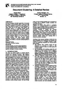
perature the particle growth seems to start later, but reaches the same concentration as at the lower temperature. It must be noted that we have not included coagulation and surface growth in our model. The ‘particle’ concentration will drastically change in the presence of coagulation. Also as bigger particles are formed, surface growth will result in the depletion of the smaller reactive species. This will slow down the clustering reactions and hence the production rate of particles. 4.2. Reaction pathways This section discusses the dominant pathways in the reaction mechanism. Figure 5 is a legend showing what various arrows denote in the figures depicting the reaction pathway. In figures 6–9, we plot the most prominent reactions for a 2740
given set of conditions at a time when steady state is reached. Again the anionic and neutral pathways are plotted separately for clarity. Figure 6 shows the anionic pathway for Tgas = 500 K and an ion density of 3 × 109 cm−3 . Only reactions with a net rate greater than 10−16 mol cm−3 s−1 are shown. We observe two main anionic clustering pathways, which involve silyl and silylene negative clusters, respectively. Both reaction chains are based on a negative silylene or silyl reacting with a neutral SiH4 molecule and eliminating H2 . These are reactions 43 and 46 in table 2 with i = 1 and j = 2. Consequently, the most prominent ‘particles’ formed are − Si11 H− 23 and Si11 H22 B anions, which are produced at the rate −14 −3 −1 of 10 mol cm s and 10−13 mol cm−3 s−1 , respectively. The silyl anion chain is similar to the simple sequence
Modelling of silicon hydride clustering Si (n) decreases
H
increases 2
3 -
0.11
Si3 H 7
Si2 H 4B
-
2n + 2
0.12
Si3 H 6B
0.11
5
4 -
Si2 H 5
-
Si4 H 9
-
Si4 H 8B
6 -
68.4
-
7 -
Si5 H 11 Si5 H 10B
-
-
Si7 H 15
Si6 H 12B
-
9
8 -
Si6 H 13
Si7 H 14B
-
123
Si8 H 16B
10 -
Si8 H 17
-
Si9 H 18B
11 -
Si9 H 19
Si10H 21
-
Si10H 20B
Anions
-
5.8
9.6 0
38.6
2n + 1
Neutrals
Si11H 24
Si2 H 6
.36
.
0.46
0.25
0.17 0.12
Si
Si2 H 5
0.13
.
.
Si
.
.
Si
.
Si
Si
.
Si
0.14
0.16
0.89
Si11H 23
.
Si
Si
0.26
2n (B)
0.13
.
Si.
Si2 H 4B
.
Si.
0.14
2n (A)
0.26 Si2 H 4A
2n
Figure 7. Dominant neutral reaction pathways at steady-state (Tgas = 500 K, Ni = 3 × 109 cm−3 ); the numbers indicate net reaction rates in units of 10−15 mol cm−3 s−1 . Si (n)
increases 2
3
decreases
H
4
Si3 H 8
Si4 H 10
6.7
5
6
7
Si5 H 12
Si6 H 14
8
Si7 H 16
9
10
11
Si8 H 18
Si9 H 20
Si10H 22
Si11H 24
Si11H 23
3.3
Si2 H 5
Si3 H 7
Si4 H 9
Si5 H 11
Si6 H 13
Si7 H 15
Si8 H 17
Si9 H 19
Si10H 21
Si2 H 4B
Si3 H 6B
Si4 H 8B
Si5 H 10B
Si6 H 12B
Si7 H 14B
Si8 H 16B
Si9 H 18B
Si10 H20 B
Neutrals 2.1
0.66 7.5
2n + 1
.
.
-
Si2 H 5
17.9
Si
17.5
.
Si
.
.
Si
0.52
Anions
3.4 .
Si
Si
.
Si
Si
8.1
0.8
3.4
.
Si
3.3
-
-
Si11H 23
-
Si12H 25
Si13H 25
1.3 2.8
2n (B)
Si2 H 4B
20.2
.
. Si. 20.1
. Si. 19.7
Si.
.
21.5
. Si.
21.7
0.7
. Si.
21.76
.
Si.
.
Si.
20
Si.
19.7
20.2
Si11H 22B
-
Si12H 24B
-
Si13H 26B
-
1.13
Figure 8. Dominant anionic reaction pathways at steady-state (Tgas = 500 K, Ni = 1 × 1011 cm−3 ); the numbers indicate net reaction rates in units of 10−11 mol cm−3 s−1 (all unlabelled reaction rates are of the order 10−12 mol cm−3 s−1 ).
hypothesized by other authors [18, 22, 46, 47]. The anionic silylene chain has nearly a constant reaction rate. However in the anionic silyl chain, we note that the chain slows down − in the conversion from Si4 H− 9 to Si5 H11 and further in the − − conversion from Si7 H15 to Si8 H17 . These reactions (involving silane addition and corresponding H2 elimination) have �G values of 7 kcal mol−1 and 9.4 kcal mol−1 , respectively, which are higher than the other reactions in this chain. Si8 H17 and Si5 H12 have a relatively smaller electron affinity than the other silyls due to their structure. In both cases, the radical rests on a silicon atom at the end of a chain, whereas for other silyls it rests on a silicon atom that is attached to at least two − other silicon atoms. The formation of Si5 H− 11 and Si8 H17 is thus relatively unfavourable compared to other silyl anions − and leads to the increase in concentration of Si4 H− 9 and Si7 H15 as discussed before. There are also Si2 H4 B insertions due to reactions with Si2 H6 and corresponding H2 eliminations. However, these
reactions are nearly three orders of magnitude slower than the chains mentioned above where the neutral reaction partner is SiH4 . This is due to the smaller concentrations of Si2 H6 − compared to SiH4 . The reactions of Si4 H− 9 and Si7 H15 with Si2 H6 (with corresponding H2 elimination), leading to the − formation of Si6 H− 13 and Si9 H19 , respectively, are faster due − to the relatively high concentrations of Si4 H− 9 and Si7 H15 . These reactions are favourable due to a negative change in free energy. Thus, these two reactions are noticeable in the reaction pathway shown. The main loss mechanism for anions is the neutralization reactions, which are all assumed to have the same rate constant. The rates of neutralization reactions are smaller than the dominant clustering pathway. However, as discussed − earlier the higher concentrations of Si4 H− 9 and Si7 H15 increases the neutralization rates of these two species. There are also other routes which lead to the removal of − Si4 H− 9 and Si7 H15 , as seen from the figure. These involve a 2741
U V Bhandarkar et al Si (n) decreases
H
increases 2
3 -
Si2 H 4B
Si3 H 7
-
5
4 -
Si2 H 5
Si4 H 9
Si3 H 6B
-
-
Si4 H 8B
6 -
-
6.7
7 -
Si5 H 11
Si6 H 13
-
Si5 H 10B
Si7 H 15
Si6 H 12B
-
9
8 -
Si7 H 14B
3.3 -
-
Si8 H 16B
10 -
Si8 H 17
-
11 -
Si9 H 19
Si10H 21
Si9 H 18B
-
Si10H 20B
-
Anions
31
2n + 2
46.8 1.4
2n + 1
Si2 H 5
3.2
2n (B)
Si11H 24
Si2 H 6
Si2 H 4B
0.37 .
Si
0.66 . Si
.
. Si
Si
2.1
.
Si
.
Si
0.32 .
Si
.
.
Si.
Si
.
.
Si.
.
Si.
Si.
1.08
1.2
Si2 H 4A
Si.
.
. Si.
.
Si.
Neutrals
0.25
Si11H 22
2n
2n - 1
.
Si.
.
Si
.
2n - 2 (B)
0.76 Si11H 23
1.03
2.3 . Si.
184.3
2n (A)
1.2
.
Si.
Si
.
Si
.
0.11
Si
.
Si
.
Si
Si11H 21
.
Si.
Figure 9. Dominant neutral reaction pathways at steady-state (Tgas = 500 K, Ni = 1 × 1011 cm−3 ); the numbers indicate net reaction rates in units of 10−11 mol cm−3 s−1 (all unlabelled reaction rates are of the order 10−12 mol cm−3 s−1 ).
reaction with SiH3 or Si2 H5 with H2 elimination. This leads to the formation of bigger anionic silylenes. Figure 7 shows that none of the neutral clustering reactions are as fast as the ion–neutral reactions. There are some fast clustering reactions involving SiH2 insertions into small neutral silicon hydrides. Large neutral clusters are mainly produced through neutralization reactions which involve the recombination of the anions with SiH+3 . Due to the increase in Si8 H18 production from the neutralization reaction discussed above, we see that further electron dissociation and ring formation reaction rates also increase. These lead to the formation of Si7 H14 B and Si7 H14 respectively. Figures 8 and 9 show the anion and neutral clustering pathways at the higher positive ion density of 1 × 1011 cm−3 . Here the most prominent ‘particle’ formation reactions have a reaction rate of the order of 10−10 mol cm−3 s−1 . The figure shows all reactions which have a rate faster than 10−12 mol cm−3 s−1 . We see that the clustering pathways remain the same but have a rate which is faster than that for the case of an ion density of 3 × 109 cm−3 . As noted before, the clustering chain involving anionic silyls shows − a bottleneck at the conversion from Si4 H− 9 to Si5 H11 and − − from Si7 H15 to Si8 H17 . Reactions with Si2 H6 again provide a − feasible alternative for the removal of Si4 H− 9 and Si7 H15 . The neutralization reactions also provide an alternative pathway − for Si4 H− 9 and Si7 H15 removal. In fact the increased positive ion density leads to an increase in reaction rates of all neutralization reactions, which leads to creation of more neutral species. Significant amounts of Si11 H23 and Si11 H24 are formed as a consequence. In addition, the increased formation rates of Si8 H18 and Si5 H12 due to neutralization of − Si7 H− 15 and Si4 H9 leads to an increase in their density. This 2742
increases the reaction rate for the corresponding electroninduced dissociation to Si7 H14 B and Si4 H8 B, respectively, and further ring formation reactions. Subsequent electroninduced dissociation reaction of Si7 H14 leads to the formation of Si6 H11 . Thus, dehydrogenation and formation of cyclic silicon hydrides are strongly enhanced compared to the case with a positive ion density of 3 × 109 cm−3 . Mass Spectra In figures 10—12 we plot histograms of the cluster mass distribution for the steady state system. These diagrams can be considered as theoretically predicted mass spectra. The anions and neutrals have been plotted separately for clarity. In figure 10, the histograms are for an ion density of 3 × 109 cm−3 and a gas temperature of 500 K. For all anionic clusters, only two different species are observed in significant numbers within a size group (i.e. with same number of Si atoms). These are always the most hydrogenated silylene and silyl anion of a particular size. Consequently among neutral clusters with more than three silicon atoms, the corresponding products of neutralization (a silane and a silyl respectively) show the maximum concentration. As observed earlier, among clusters with more than three silicon atoms, the concentration of anionic clusters is larger than that of neutral clusters. Figure 11 shows a similar plot but at an ion density of 1×1011 cm−3 . The presence of more dehydrogenated clusters than in figure 10 is obvious. In some cases, dehydrogenated clusters are more abundant than fully saturated ones. This is especially true for neutral clusters. Also, the concentration of the neutral clusters is larger than that of the anions as observed
Modelling of silicon hydride clustering
Anions
Concentration(cm - 3)
1014
10
12
10
10
108
10
6
104
100
Mass (amu)
200
300
200
300
Neutrals
Concentration(cm - 3 )
1014
10
12
10
10
108
10
6
104
100
Mass (amu)
Figure 10. Predominant species at steady-state (Tgas = 500 K, Ni = 3 × 109 cm−3 ).
earlier. We can qualitatively compare this with the results of Hollenstein et al [48], who have obtained mass spectra of silicon hydride clusters in their experiments with RF plasmas using pure silane or silane mixed with oxygen. The authors have used a reactor uniformly heated to 473 K. In their experiments, they observed anionic species which were more dehydrogenated than those predicted by our mechanism. The authors proposed a model wherein a silyl anion radical chain propagates, similar to our reaction chain where a negative silyl ion reacts with SiH4 with H2 elimination. To explain the increased dehydrogenation observed in their experiments, the authors assumed that some of these reactions lead to elimination of two H2 molecules. The elimination of two H2 molecules should however be a less important reaction, since such reactions would require more energy to proceed. The presence of a bottleneck in the silyl anion clustering chain also makes this chain slower than the silylene anion clustering chain. Hollenstein et al [48] also observed an exponential decrease in the number density of anions for bigger clusters whereas our simulations indicate that all anionic clusters with more than five silicon atoms (except for anionic clusters with seven silicon atoms) show nearly equal density. However, in these discussions we should bear in mind that mass spectra predicted by our simulations and those observed by Hollenstein et al [48] correspond to different situations. Our model predicts the spectra in an active steady state discharge whereas Hollenstein et al [48] had to observe
their mass spectra in the afterglow of a pulsed discharge. The measured mass spectra are likely to be modified by electron attachment, which becomes very efficient in the cold afterglow of a plasma. Also, the plots by Hollenstein et al [18, 46] are uncorrected for any mass-dependent falloff in the sensitivity of the spectrometer, which may lead to discrepancies at higher masses in the spectrum. The experimental mass spectra may also reflect the influence of different transport properties of different size clusters. Besides, it should be noted that our mechanism currently does not account for vibrational excitation of species which may enhance certain reactions [22]. We have also not included any coagulation or surface growth mechanisms in our model. The cluster concentrations from our simulations may look different in the presence of these mechanisms. 4.3. Role of SiH2 species According to Watanabe and co-workers [16, 17], SiH2 is the major growth species in the clustering observed in silane plasmas. SiH2 insertion was also noted as a prominent reaction in the thermal reaction mechanism [24]. We find that SiH2 insertions do indeed play an important role in the formation of smaller silicon hydride clusters. These reactions have a reaction rate on the order of ion–neutral clustering reactions, but only up to clusters with three silicon atoms. At larger sizes we do not observe any important reactions 2743
U V Bhandarkar et al
Anions
Concentration(cm - 3)
1014
10
12
10
10
108
10
6
104
100
Mass (amu)
200
300
200
300
Neutrals
Concentration(cm - 3 )
1014
10
12
10
10
108
10
6
104
100
Mass (amu)
Figure 11. Predominant species at steady-state (Tgas = 500 K, Ni = 1 × 1011 cm−3 ).
involving SiH2 . It must be mentioned that the reaction rate constants for SiH2 insertions into smaller neutral clusters (having one or two silicon atoms) were obtained directly from the literature, while those for the larger clusters were estimated (as discussed in the model description). However SiH2 insertion is largely a thermal reaction driven by the temperature of the gas, and we notice that this insertion rate into bigger clusters increases by nearly an order of magnitude while going from 500 K to 650 K. Thus, we expect these reactions to be important for the larger clusters only at higher gas temperatures. In summary we observe that clustering predominantly occurs via the anionic pathway, though neutral reactions are important for the smaller clusters. At present, our model suggests that dehydrogenation and formation of cyclic structures results mainly from electron-induced dissociation of neutrals. Reactions leading to dehydrogenation are present also in the anion–neutral mechanism, but the predominance of SiH4 in the gas leads to fast reactions only between anions and SiH4 , which preserve the degree of dehydrogenation. In fact clustering via this route is at least three orders of magnitude faster than any competing neutral pathway. In essence, we expect that larger linear clusters are formed in the anionic system, while dehydrogenation and ring formation occur among the neutral clusters. 2744
4.4. Role of wall sticking coefficients In all the above calculations, we have assumed that neutrals diffusing to the wall stick with a probability of unity. Sticking coefficients (γ ) on polycrystalline silicon are known for reactive radicals like SiH2 , SiH3 , Si2 H4 B and Si2 H5 . For disilane, γ is known to be less than 10−3 [28, 49, 50]. Data for larger clusters are unavailable. To study the effect of wall sticking coefficients, we have also carried out calculations (Ni = 3 × 109 cm−3 and Tgas = 500 K) assuming γ to equal unity for radicals containing one or two silicon atoms. For disilane and all larger clusters, we have assumed γ to be 10−3 . Subsequently, the slower diffusion of neutral clusters, compared to the cases where the sticking coefficient is assumed to be unity for all species, leads to an accumulation of neutrals. This longer residence time also leads to an increased probability of dehydrogenation of the neutrals, and we observe higher concentrations of dehydrogenated species among the neutrals, as can be seen from figure 12. The ion–neutral clustering rate still remains much faster than the neutral clustering rate. This picture is perhaps a better representation of the clustering mechanism, as it accounts for the fast clustering as well as the dehydrogenation observed in experiments [48]. It should be mentioned that the neutral clustering pathway becomes comparable to the anionic pathway only
Modelling of silicon hydride clustering
Anions
Concentration(cm - 3)
1014
10
12
10
10
108
10
6
104
100
Mass (amu)
200
300
200
300
Neutrals
Concentration(cm - 3 )
1014
10
12
10
10
108
10
6
104
100
Mass (amu)
Figure 12. Predominant species at 1 s (Tgas = 500 K, Ni = 3 × 109 cm−3 , γ = 0.001 for neutral clusters with three or more silicon atoms).
if γ is assumed to be 10−3 for SiH2 and SiH3 , since this increases the reaction rate of SiH2 and SiH3 insertion reactions. However, since γ is known to be closer to one for these species, the predominance of anionic clustering seems to be more realistic.
Acknowledgments
This work was supported by NSF under grant ECS 9731568, by the University of Minnesota Supercomputing Institute, and by the University at Buffalo (SUNY) Center for Computational Research.
5. Conclusion
The process of clustering in low-pressure silane plasmas was studied by developing a detailed reaction mechanism that included both thermal and plasma chemistries. The thermochemical properties of all clusters were calculated using group additivity rules. Reactions were defined and their reaction rates were estimated based on known rates of reactions of small molecules. Langevin rates reduced by an order of magnitude were used for anion–neutral reactions. It was found that increasing ion density (i.e. RF power density) leads to faster clustering and more dehydrogenated clusters. The anionic pathway was found to be the main pathway for silicon hydride clustering. SiH2 insertion in neutral clusters was found to be important only among the small silicon hydrides with up to three or four silicon atoms. Dehydrogenation and ring formation mostly occur through neutral reactions. In the future we plan to add coagulation of clusters and surface chemistry to the model and then to extend it to a two-dimensional system. In the long term we plan to couple this model to a self-consistent plasma model.
References [1] Semiconductor Industry Association 1997 The National Technology Roadmap for Semiconductors Technical Report (unpublished) see http://notes.sematech.org/ NTRS/PubINTRS.nsf/pages/97pelec.htm/ [2] Scholz S M, Carrot G, Hilborn J, Dutta J, Valmalette J-C, Hoffman H and Luciani A 1998 Surface controlled nanoscale materials for high added value application Mater. Res. Soc. (Warrendale, PA: Materials Research Society) pp 79–84 [3] Itoh T 1997 Rev. Laser Eng. 25 738 [4] Milewski P D, Streiffer S K, Kingon A I, Shmagin I K, Kolbas R M and Krishnankutty S 1998 J. Soc. Inform. Display 6 143 [5] Somasundaran P and Chen T 1998 Surface controlled nanoscale materials for the high-added-value applications Mater. Res. Soc. (Warrendale, PA: Materials Research Society) pp 161–72 [6] Longuead C, Kleider J P, Roca i Cabarrocas P, Hamma S, Meaudre R and Meaudre M 1998 J. Non-Cryst. Solids 227–230 96 [7] Meaudre M, Meaudre R, Butte R, Vignoli S, Longeaud C, 2745
U V Bhandarkar et al
[8] [9] [10] [11] [12] [13] [14] [15] [16] [17] [18] [19] [20] [21] [22] [23] [24] [25] [26] [27] [28] [29]
2746
Kleider J P and Roca i Cabarrocas P 1999 J. Appl. Phys. 86 946 Boufendi L, Plain A, Blondeau J Ph, Bouchoule A, Laure C and Toogood M 1992 Appl. Phys. Lett. 60 169 Boufendi L, Bouchoule A, Porteus R K, Blondeau J Ph, Plain A and Laure C 1993 J. Appl. Phys. 73 2160 Bouchoule A and Boufendi L 1993 Plasma Sources Sci. Technol. 2 204 Bouchoule A and Boufendi L 1994 Plasma Sources Sci. Technol. 3 292 Boufendi L and Bouchoule A 1994 Plasma Sources Sci. Technol. 3 262 Shiratani M, Kawasaki H, Fukuzawa T and Watanabe Y 1994 Appl. Phys. Lett. 65 1900 Kawasaki H, Fukuzawa T, Tsuruoka H, Yoshioka T, Shiratani M and Watanabe Y 1994 Japan. J. Appl. Phys. 33 4198 Watanabe Y, Shiratani M, Kawasaki H, Singh S, Fukuzawa T, Ueda Y and Ohkura H 1996 J. Vac. Sci. Technol. A 14 540 Watanabe Y, Shiratani M, Fukuzawa T, Kawasaki H, Ueda Y, Singh S and Ohkura H 1996 J. Vac. Sci. Technol. A 14 995 Fukuzawa T, Obata K, Kawasaki H, Shiratani M and Watanabe Y 1996 J. Appl. Phys. 80 3202 Howling A A, Sansonnens L, Dorrier J-L and Hollenstein C 1993 J. Phys. D: Appl. Phys. 26 1003 Courteille C, Dorrier J-L, Hollenstein C, Sansonnens L and Howling A A 1996 Plasma Sources Sci. Technol. 5 210 Mandich M L, Reents W D and Kolenbrander K D 1990 J. Chem. Phys. 92 437 Raghavachari K 1992 J. Chem. Phys. 96 4440 Fridman A A, Boufendi L, Hbid T, Potapkin B V and Bouchoule A 1996 J. Appl. Phys. 79 1303 Sansonnens L, Howling A A, Hollenstein C and Dorrier J-L 1994 J. Phys. D: Appl. Phys. 27 1406 Swihart M T and Girshick S L 1999 J. Phys. Chem. B 103 64 Girshick S L, Swihart M T, Suh S-M, Mahajan M R and Nijhawan S 2000 J. Electrochem. Soc. 147 2303–11 Benson S 1976 Thermochemical Kinetics (New York: Wiley) ch 2, pp 18–54 Katzer G, Herst M C, Sax A F and Kalcher J 1997 J. Phys. Chem. A 101 1942 Ho P, Coltrin M E and Breiland W 1994 J. Phys. Chem. 98 10 138 Potzinger P and Lampe F W 1969 J. Phys. Chem. 73 3912
[30] Haaland P 1990 J. Chem. Phys. 93 4066 [31] Srivastava S K, Krishnakumar E and DeSouza A C 1991 Int. J. Mass Spectrom. Ion Proc. 107–115 83 [32] Tanaka H, Boesten L, Sato H, Kimura M, Dillon M A and Spence D 1990 J. Phys. B: At. Mol. Opt. Phys. 23 577 [33] Tronc M, Hitchcock A and Edard F 1989 J. Phys. B: At. Mol. Opt. Phys. 22 L207 [34] Chatham H, Hils D, Robertson R R and Gallagher A C 1984 J. Chem. Phys. 81 1770 [35] Perrin J, Leroy O and Bordage M C 1996 Contrib. Plasma Phys. 36 1–3 [36] Krishnakumar E, Srivastava S K and Iga I 1991 Int. J. Mass Spectrom. Ion Proc. 103 107 [37] Meeks E, Larson R S, Ho P, Apblett C, Han S M, Edelberg E and Aydil E S 1998 J. Vac. Sci. Technol. A 16 544 [38] Perrin J, Schmitt J P M, De Rosny G, Drevillon B, Huc J and Lloret A 1982 Chem. Phys. 73 383 [39] Bordage M C 1997 Personal communications [40] Swihart M T 2000 Phys. Chem. A 104 6083–7 [41] Hickman A P 1979 J. Chem. Phys. 70 4872 [42] Gallagher A 2000 A model of particle growth in silane discharges Phys. Rev. E 62 2960–706 [43] Lutz A E, Kee R J and Miller J A 1996 SENKIN: A Fortran Program for Predicting Homogeneous Gas Phase Chemical Kinetics with Sensitivity Analysis (Sandia National Laboratories) [44] Reid R C, Prausnitz J M and Sherwood T K 1977 The Properties of Gases and Liquids vol 3 (New York: McGraw-Hill) ch 11 [45] Lieberman M A and A J Lichtenberg 1994 Principles of Plasma Discharges and Materials Processing (New York: Wiley) ch 10 [46] Hollenstein C, Schwarzenbach W, Howling A A, Courteille C, Dorrier J-L and Sansonnens L 1996 J. Vac. Sci. Technol. A 14 535 [47] Girshick S L 1997 J. Chem. Phys. 107 1948 [48] Hollenstein C, Howling A A, Couteille C, Dorrier J-L, Sansonnens L, Magni D, and Muller H 1998 Amorphous and microcrystalline silicon technology Mater. Res. Soc. vol 507 (Warrendale, PA: Materials Research Society) pp 547–57 [49] Coltrin M E, Kee R J and Miller J A 1986 J. Electrochem. Soc. 133 1206 [50] Buss R J, Ho P, Breiland W G and Coltrin M E 1988 J. Appl. Phys. 63 2802