IEEE TRANSACTIONS ON NUCLEAR SCIENCE, VOL. 54, NO. 4, AUGUST 2007
935
Models and Algorithmic Limits for an ECC-Based Approach to Hardening Sub-100-nm SRAMs Michael A. Bajura, Member, IEEE, Younes Boulghassoul, Member, IEEE, Riaz Naseer, Student Member, IEEE, Sandeepan DasGupta, Student Member, IEEE, Arthur F. Witulski, Senior Member, IEEE, Jeff Sondeen, Scott D. Stansberry, Jeffrey Draper, Member, IEEE, Lloyd W. Massengill, Fellow, IEEE, and John N. Damoulakis
Abstract—A mathematical bit error rate (BER) model for upsets in memories protected by error-correcting codes (ECCs) and scrubbing is derived. This model is compared with expected upset rates for sub-100-nm SRAM memories in space environments. Because sub-100-nm SRAM memory cells can be upset by a critical charge ( crit ) of 1.1 fC or less, they may exhibit significantly higher upset rates than those reported in earlier technologies. Because of this, single-bit-correcting ECCs may become impractical due to memory scrubbing rate limitations. The overhead needed for protecting memories with a triple-bit-correcting ECC is examined relative to an approximate 2X “process generation” scaling penalty in area, speed, and power. Index Terms—Error correction coding, memory fault tolerance, radiation effects.
I. INTRODUCTION N OVER FIVE decades of aggressive scaling, CMOS transistor technology has rapidly progressed towards nanotechnology-scale feature sizes. However, this continuous shrinking of device dimensions has also strongly affected device and circuit radiation sensitivity [1]. SRAM circuits in particular have experienced a steady decrease in cell nodal capacitances and operating voltage margins [2]. This trend has reduced both the crit[3] and corresponding linear energy transfer ical charge (LET) threshold [4] capable of corrupting a stored bit. This has drastically increased the candidate population of ionizing particles which can affect memory cells, both directly and indirectly [5], and therefore also the likelihood of bit upsets. The frequency of single-bit upsets (SBUs), and more recently multi-bit upsets (MBUs), is now a major reliability concern in commercial electronics [1] (Sun Microsystems), [2] (Texas Instruments), [3] (Virage Logic Corporation), [6], [7] (Intel), [8] (Cypress Semiconductor), [9] (IBM).
I
Manuscript received October 6, 2006; revised December 20, 2006. This work was supported by the Defense Advanced Research Projects Agency (DARPA) Microsystems Technology Office under Award No. N66001-04-1-8914. Any opinions, findings, and conclusions or recommendations expressed in this publication are those of the author(s) and do not necessarily reflect the views of DARPA/MTO or the U.S. Government. The U.S. Government is authorized to reproduce and distribute reprints for Governmental purposes notwithstanding any copyright notation that may appear hereon. M. Bajura, Y. Boulghassoul, R. Naseer, J. Sondeen, S. Stansberry, J. Draper, and J. Damoulakis are with the University of Southern California Viterbi School of Engineering Information Sciences Institute, Marina Del Rey, CA 90292 USA (e-mail:
[email protected];
[email protected];
[email protected];
[email protected];
[email protected];
[email protected];
[email protected]). S. DasGupta, A. Witulski, and L. Massengill are with the Institute for Space and Defense Electronics, Vanderbilt University, Nashville, TN 37235-1553 USA (e-mail:
[email protected];
[email protected];
[email protected]). Digital Object Identifier 10.1109/TNS.2007.892119
The issue of SRAM soft-error vulnerability, mainly caused by the single-event upset (SEU) and single-event transient (SET) phenomena [10], [11], has prompted the development of two general hardening approaches, both aimed at reducing SRAM bit error rates (BERs), measured in number of errors/bit-day, to within acceptable reliability margins. In a circuit-based hardening approach, both the individual memory cell and control structure designs of a memory array are hardened through the use of circuit and layout radiation-hardening-by-design (RHBD) techniques and/or custom radiationhardened foundry processes [12], [13]. In this case, the BER of the SRAM is largely dictated by the physical, or individual, BER of the memory cell and system design. However, the area, power and speed penalties associated with hardening individual memory cells may negate the expected technological gains from process generation scaling [14], [15]. In a system-based hardening approach, error-correcting codes (ECCs) and periodic memory scrubbing (i.e., checking a memory for errors) are used to improve the effective BER of a system over its underlying physical BER. This approach requires finding a careful balance between physical cell BERs, SEU-inducing mechanisms, ECC redundancy (which requires extra memory cells), and scrubbing rate which can increase power usage. The approach advanced here is a hybrid design which hardens only the ECC and control circuitry of a memory array using RHBD circuit and layout techniques, while leaving the commercial density, technological scaling, and intrinsic physical BER of the memory cells intact. ECCs, bit interleaving, and memory scrubbing are used in conjunction to achieve a low overall effective BER without requiring the use of custom radiation-hardened foundry processes. This general approach has been proposed by many authors including Baumann [2] as “the most effective method of dealing with soft errors in memory” and by Slayman [1] and Saleh [16] in similar wording. This approach may yield improved, denser hardened SRAM arrays than either a circuit-oriented or a system (ECC)-oriented approach alone, and may also continue to scale with technology improvements. Three goals are defined for this hardening approach study: 1) It applies to 90 nm and smaller semiconductor process technologies. 2) It achieves an effective BER of errors/bit-day in space applications. 3) It does not incur more than “one process generation penalty” (approximately 2X scaling in area, speed, and power) when compared to similar nonhardened SRAMs designed in the same technology. The feasibility of reaching these goals is suggested by the observation that, by adding up to 100% redundancy to a
0018-9499/$25.00 © 2007 IEEE
936
IEEE TRANSACTIONS ON NUCLEAR SCIENCE, VOL. 54, NO. 4, AUGUST 2007
memory array, relatively strong ECC codes may be employed, e.g., the triple-bit-correcting Golay code, which have better error-correcting properties than common codes such as the single-error-correct/double-error-detect (SEC/DED) Hamming encoding or the Triple Modular Redundancy (TMR) encoding which requires 200% area overhead. The remainder of this paper proceeds as follows. Section II analyzes the effectiveness of differing ECC strengths versus both scrubbing rate and physical BER derived from an operational model. It is shown that even with strong ECC codes, to maintain a target system BER, the scrubbing rate must increase linearly with the physical BER. If practical upper bounds on scrubbing rate are also considered, a maximum allowable physical BER is established. Section III, based on computer simulations of modeled 90-nm SRAMs, quantifies the sensitivity of a dense six-transistor (6T) commercial memory cell through the . From this, the expected determination of its critical charge physical BER of the 90-nm SRAM cell is computed for several space-radiation environments using the CREME96 code [17]. Given the physical BERs computed in Section III, Section IV discusses optimal combinations of ECC strength and scrubbing frequency needed to obtain a errors/bit-day reliability goal in a 90-nm SRAM in space applications. For physical BERs above a certain threshold, single-bit error correcting codes appear to become impractical as they may require too high of a scrubbing rate. Finally, Section V compares the overhead of implementing an ECC-protected memory based on a triple-bit-correcting algorithm versus a baseline case and a 2X scaling design goal. II. HARDENING WITH ERROR-CORRECTING CODES AND SCRUBBING To preserve the flow of argument, the results of this section are presented here, and the reader is referred to the Appendix for the detailed mathematical derivations and assumptions concerning Figs. 1, 2, and 3.
memory overhead to be able to correct for one single-bit error in a three-bit word. Another code, the (24, 12, 8) Golay code, has a 100% memory overhead but can correct for triple-bit errors and detect quadruple-bit errors in a 24-bit word. The complexity of an ECC code is related to the number of bits it can correct, which also relates to the processing required to implement it. Finding optimal solutions to coding density and ease of implementation is an entire field of study in itself and the reader is referred to many textbooks on the subject [23]. For clarity in the rest of this paper, effective BERs are given in terms of the total size of an ECC-protected memory, and not in terms of the amount of data stored. The effective BER can be normalized in terms of to include the overhead of the , which ranges from 1 to extra memory by multiplying by 3 for the ECCs discussed here. B. ECC Model Assumptions The effectiveness of an ECC code in a memory system is evaluated by calculating the probability of getting an uncorrectable error within a word. An uncorrectable error occurs when the number of upset bits (or words) exceeds what can be corrected by the ECC between consecutive memory scrubbing or other access cycles. Using this expression, a system’s worst-case effective BER is calculated as the product of the probability of getting an uncorrectable error between scrubbing cycles times the scrubbing cycle rate. The input parameters needed are the physical cell BER, the type of ECC code used, and the scrubbing cycle rate, or scrubbing rate. The assumption of uncorrelated bit errors, on which this analysis is based, is invalidated by the occurrence of MBUs within the same ECC word. Such events are most often caused by a large area of photo-generated charge following the impact of a high mass ion [24]; from an ion strike at grazing angle affecting multiple memory cells [25]; from byproducts of a nuclear spallation having occurred in overlaying materials [26]; or from strikes on the memory control circuitry that result in the corruption of an entire word line [27].
A. ECC Parameters and Coding Density The essential parameters of an ECC are denoted by or , where is the total number of bits (words) used, is the number of bits (words) and, usually for bit-oriented codes, is the number of bit-differences, or Hamming distance, between valid codewords within a code. In any error-correcting code, is always greater than , such that the difference represents the amount of redundancy in a particular code. A common code in computer memories is the (72, 64, 4) singleerror-correct/double-error-detect (SEC/DED) code [18]–[22]. It uses 72 total bits (9 bytes) to encode 64 bits (8 bytes), with a Hamming distance of four between codewords. It is a SEC/DED code because a single-bit error can be correctly mapped back to its original codeword, or corrected, while a double-bit error, being two bit differences from two or more valid codewords, can be detected but not uniquely mapped back to a valid codeword. In a memory-hardening application, the difference between and represents the additional overhead required for a particular ECC code. The familiar hardening technique of Triple-Modular Redundancy (TMR), whereby three memory cells are used to store one bit, implements a (3, 1, 3) ECC code: it needs a 200%
C. Mitigations for Model Assumptions A commonly-accepted approach to mitigating MBU memory strikes is bit interleaving [1], [2], [8], whereby successive bits in the same logical ECC word are physically separated by interposing bits which are mapped to other logical ECC words. In this way, every MBU of physically adjacent memory cells is transformed into multiple SBUs in different ECC-protected memory words. These SBUs appear to be uncorrelated events relative to the ECC algorithm used. As memory cell sizes have been shrinking, the number of adjacent cells affected by MBUs has been growing, and thus, too, the minimum interleaving distance, measured in memory cell spacings, needed to mitigate MBU effects. Baumann [2] generally recommends a minimum of four to eight bits of interleaving, while Radaelli [8] reports a minimum of six cells in a 150-nm SRAM technology, Maiz [7] six or more in 130-nm and 90-nm technologies, and Meaney [9] reports using a “by 64” interleaving scheme for an L2 cache design in IBM’s z990 processor. Interleaving is also common using words at the board level, e.g., the (144, 128) S4EC SSC/DSD “chip kill” encoding which can correct for memory
BAJURA et al.: MODELS AND ALGORITHMIC LIMITS FOR AN ECC-BASED APPROACH TO HARDENING SUB-100-nm SRAMS
937
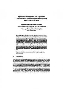
Fig. 1. P(ECC failure) per scrub cycle versus (scrubbing rate/physical BER) ratio for 22-bit word single, double, and triple-bit-correcting ECCs and TMR.
Fig. 2. Effective BER reduction factor over physical BER versus (scrubbing rate/physical BER) ratio for 22-bit word single, double, and triple-bit-correcting ECCs and TMR.
errors in case an entire 4-bit memory chip becomes “killed” or inoperable. While such chip kill codes are somewhat stronger than a simple single-bit-correcting block code, they still behave similarly to single-bit-correcting codes in the analysis of the following section. Two or more uncorrelated errors are likely to break such a code, and grouping data into nibbles or larger words does not provide significant additional protection from MBU effects, when bit interleaving is considered. Depending on memory layout and ECC mapping, in structures such as SRAM caches, SET strikes on memory control circuitry can affect an entire word line and potentially cause simultaneous MBUs within the same ECC-protected memory word [27]. In these cases, memory control circuitry must be hardened sufficiently to ensure that the BER associated with the memory control circuitry is lower than the desired effective BER of the memory system. Similarly the circuitry associated with ECC encoding and decoding must be sufficiently hardened so that it also does not limit system performance. The exact cross section of various structures can be dependent on both operating frequency and SRAM architecture. Common control circuitry, such as ECC encode and decode circuits, would likely show a cross-sectional frequency dependence, but not a device size dependence, since SEU strikes only affect the current operations of these circuits. Structures such as word drivers, in which SEEs could affect many bits and memory words simultaneously, could need stronger protection to reduce their cross-sections which normally scale according to the number of bits affected. However, in an architecture which interleaves ECC codewords across multiple banks, the cross section of a word-driver would not directly scale with the number of bits affected since a failure would not, by itself, defeat the ECC. The reader is referred to part D of the Appendix for models incorporating frequency-dependent read errors.
also as a function of the ratio of the scrubbing rate to the physical BER. Curves are shown for a 22-bit (22,16,4) single-bit-correcting ECC, Single; two hypothetical ECCs which can correct for double-bit and triple-bit errors in a 22-bit word, Double and Triple; and (single-bit-correcting) TMR, TMR. Note that both figures are in log-log scaling. Note also that in cases where the physical BER is known to within a particular confidence level (e.g., 95% certain that the true BER lies between and ), the upper bounds of this interval should be used both in Fig. 2 and in the following analysis instead of the estimated BER to assure stated operation with the same confidence level. Fig. 1 shows that when the scrubbing rate is significantly greater than the physical BER, there are inverse quadratic, cubic, and quartic reductions in the probability of getting an error on a scrub cycle with increasing scrubbing rate for single, double, and triple bit-correcting ECCs, respectively. For scrubbing rates less than the physical BER, the probability of an ECC failure on a scrubbing cycle is nearly 100%. Fig. 2 shows that when the scrubbing rate is significantly greater than the physical BER, there are inverse linear, quadratic, and cubic reductions a system’s effective BER, when compared with its physical BER, with increasing scrubbing rate for single, double, and triple bit-correcting ECCs, respectively. This trend does not begin until the scrubbing rate exceeds the physical BER by a certain threshold. Below this threshold, which is a function of the number of bits in an ECC word, there appear to be more errors in the effective BER, when compared with the physical BER, apparently caused by scrubbing! This paradox is because the ECC algorithm must invalidate entire codewords even though only a small number of bits within a particular codeword may be upset. This is illustrated by the shift between the two single-bit-correcting codes: TMR, with three-bit words; and Single, with 22-bit words. Their asymptotic slopes are both inverse linear, but their offsets are different with Single having a significant extent above the “no reduction” line indicating no reduction in effective BER. As an example, interpreting Fig. 2 to reduce the effective below the physical BER, by looking for the interBER by , we sections of the ECC curves with the reduction factor read that scrubbing must occur at a rate approximately ,
D. Analysis of ECC Strength Versus Scrubbing Rate Under the assumption of statistically uncorrelated cell upsets, Fig. 1 shows the probability of getting an error within an ECC-protected word as a function of the ratio of the scrubbing rate to the physical BER. Fig. 2 shows the relative reduction (improvement) in the effective BER compared to the physical BER,
938
IEEE TRANSACTIONS ON NUCLEAR SCIENCE, VOL. 54, NO. 4, AUGUST 2007
Fig. 3. Scrubbing rate versus physical BER needed to achieve 10 effective BER for 22-bit word single, double, triple-bit-correcting ECCs and TMR.
, , and times the physical BER using the ECCs represented by Single, TMR, Double, and Triple, respectively. We note here that the stronger 22-bit triple-bit correcting code, Triple, requires a rate of scrubbing four orders of magnitude less than that needed for the 22-bit, single-bit correcting code, Single. It also bests the commonly-accepted hardening approach TMR by two orders of magnitude. The two key points of Fig. 2 are: 1) stronger codes, in terms of number of bits corrected, have steeper slopes on log-log charts, meaning that to achieve a given level of effective system error rate improvement, stronger codes can require significantly lower scrubbing rates, and 2) the selection of word size only shifts, but does not alter the overall error-correcting strength, or slope, of an ECC. In other words, in some cases using a multi-bitcorrecting ECC with a larger word size may be better than using TMR. Fig. 3, derived from Fig. 2, shows the combinations of scrubbing rate, physical BER, and ECCs required to achieve an effec, also in log-log scaling. The curves Single, tive BER of TMR, Double, and Triple represent solutions of constant effective BER system performance for each of the codes described for Figs. 1 and 2. The two key points of Fig. 3 are: 1) at some point operating at increasingly faster scrubbing rates becomes impractical as scrub scrubbing an entire memory more frequently than cycles/day, or approximately once every 10 seconds, is a practical upper limit in most main memory systems. For memories with high physical BERs, it may be necessary to switch to a stronger ECC instead of trying to scrub faster, and 2) past a certain physical BER of approximately 0.3 errors/bit-day, even triple-bit-correcting codes, such as the code represented by the effeccurve Triple, may be inadequate to achieve a target tive BER due to the upper bound of scrubbing rate. III. INVESTIGATION OF COMMERCIAL 6T MEMORY CELL SENSITIVITY A. Simulation Setup Single-event upset investigations were performed on a 6T SRAM memory cell using the CADENCE tool suite environ-
ment. The simulated SRAM was based on an actual 90-nm commercial process design following foundry-provided high-density SRAM layout rules. To simulate the SRAM cell, it was first laid out using the Virtuoso Layout editor and a netlist was extracted using Mentor’s Calibre tool and a foundry-provided design rule deck. The netlist was then converted to equivalent subcircuit calls in order to use the appropriate transistor models provided in the manufacturer’s process design kit (PDK). Next, Hspice software was used for circuit simulation of the SRAM’s radiation response. Charge collection from heavy-ion strikes was modeled by double-exponential current sources added across the terminals of the “hit” node in the memory cell. Although time-dependent current sources present a simplified model of charge deposition and collection from ion strikes, they still accurately model the effects of a low LET ion strike, as shown below by comparisons with 3-D TCAD mixed-mode simulations. Fig. 4(a) and (b) presents a series of current pulse profiles for NMOS and PMOS transistors, respectively, resulting from 3-D TCAD mixed-mode simulations of heavy ion strikes ranging over LETs of 0.25 to 1 MeV cm /mg. The simulations were performed using ISE-TCAD 10.0’s Dessis. Both transistors’ 3-D models were calibrated for both high and low V over a range of 0 to 1.2 V to reproduce the electrical DC transistor characteristics as defined in the PDK within a 5% error margin. The characteristic parameters of the TCAD pulses, including rise times, fall times, and peak amplitudes, were then used to define double exponential pulses for both NMOS and PMOS simulated ion strikes. These pulses were injected as current stimuli inputs in the Hspice circuit simulations. The amplitude of the fitted double-exponential pulses was then modulated to find the upset/no-upset boundary for each of the radiation-sensitive transistors in the investigated SRAM cell. It should be noted that while this approach is useful in electrically estimating the critical charge needed for cell upset, it does not directly estimate the process parameters of the target technology which are not shared freely by the vendor. As such, multiple TCAD transistor models can have similar terminal electrical characteristics while presenting variations in their structure (doping profile, junction depths, buried layer location, etc.), potentially impacting parameters relevant to radiation effect studies. In our case, the initial calibrated TCAD model estimated the collection depth to be 1 m, but in our analysis we also presented results for two other candidate charge collection depths, 0.5 m and 0.25 m, indicative of technology scaling trends. B.
Simulation Results and Analysis
Fig. 4 plots the smallest double-exponential current profiles which can induce a bit-flip in the 90-nm 6T dense SRAM cell. The minimal-sized SEU-inducing pulses, when applied to the drains of the “off” NMOS and “off” PMOS transistors, have total integrated charges of 1.1 fC and 2.4 fC, respectively. The difference in minimum injected total charge required for a bit upset to occur is due to the design of the 6T cell. The cross-coupled inverters are highly asymmetric with the pull-down NMOS transistors having much stronger drive strength than the PMOS pull-ups. Under normal operating conditions, this asymmetric design improves the speed at which the SRAM can flip states.
BAJURA et al.: MODELS AND ALGORITHMIC LIMITS FOR AN ECC-BASED APPROACH TO HARDENING SUB-100-nm SRAMS
939
Fig. 5. Voltage characteristics of the 6T cell depicting the upset of the Bit and Bit internal nodes following a strike on the drain of the off NMOS.
earth radii [29], a steep increase in the physical BER may therefore be expected when compared to the previous generation of SRAM cells. IV. ECCS AND SCRUBBING RATE PROJECTIONS
Fig. 4. Charge collection photocurrent profiles (plain lines) resulting from 3-D mixed-simulations of heavy-ion strikes on (a) an NMOS transistor, and (b) a PMOS transistor. The dashed curve is the smallest fitted double-exponential pulse that induces an upset in the SRAM following a strike on (a) the “off” NMOS, and (b) the “off” PMOS.
However, it is also more sensitive to upsets, since the ability of the PMOS to provide restoring current following a strike on the drain of the off NMOS is diminished, making it more likely to . Fig. 5 shows typical flip at a lower critical charge and Bit SEU voltage characteristics following a strike on the “off” NMOS. of 1.1 fC to its corresponding Converting the minimal LET value by considering hypothetical charge collection depths of 1.0 m [28], 0.5 m, and 0.25 m, we find that the 90-nm 6T commercial cell can be upset due to ionizing particles with LETs as low as 0.11, 0.21, and 0.44 MeV cm /mg, respectively. These extremely low LET thresholds suggest that sub-100-nm SRAM cells may be sensitive to direct ionization from populations of particles previously considered as having LETs insufficient to cause SEUs. Hence, it is not excluded that in the near future, with each new with the continuing aggressive scaling of technology generation [3], the population of trapped protons, with its associated SEU concerns so far limited to secondary spallation and fractionation particles, may play an increasingly important role in BER calculations. Because of the very high p/cm s at population of trapped protons, with fluxes up to
simulations and on area informaBased on the above tion extracted from the cell layout, the CREME96 code [17] was used to calculate the physical BER of a 90-nm SRAM in a GEO orbit under solar quiet conditions at solar minimum (maximum galactic cosmic rays (GCRs)), in a GEO orbit under solar flare conditions using the worst week model (“99% worst case” environment), and in an equatorial orbit at 3000 km (apogee and perigee) using the AP8MIN trapped proton model and quiet magnetic weather conditions. All BER calculations used an into , assumed 100 mils of tegral LET spectrum for aluminum shielding, and did not include nuclear reactions from protons. Due to the uncertainty of the exact collection depth in this particular fabrication process, BER values are presented here for three possible collection depths and therefore should not be considered as “absolute”, but rather as trend estimates for comparing the effects of various space radiation environments. Table I shows the estimated scrubbing rates needed to mainsystem BER for each of the selected radiation entain a vironments over a range of charge collection depths and associated LET thresholds. The LET thresholds are used to extrapolate physical BERs for each environment. Assuming the hybrid hardening approach described here and the ECC codes depicted in Fig. 3, the scrubbing rates necessary to maintain the target system BER are tabulated for each ECC. For all three charge collection depths, the GEO solar flare environment has BERs several orders of magnitude higher than the GEO solar quiet/maximum GCR environment. In contrast, for the 3000 km equatorial orbit, the BER shows a strong dependence on the collection depth, particularly between the 0.5 m and 1.0 m depths. This demonstrates the importance of accurate charge collection depth measurements since they weight heavily the spectrum of trapped protons relevant to BER calculations. The effectiveness of the triple-bit-correcting ECC is seen in the significantly-reduced scrubbing rates needed when compared to the other ECCs. In many cases (denoted in
940
IEEE TRANSACTIONS ON NUCLEAR SCIENCE, VOL. 54, NO. 4, AUGUST 2007
TABLE I PREDICTED SCRUBBING RATES NEEDED TO ACHIEVE A 10 BER FOR A 90-NM SRAM MEMORY WITH 1.1 FC CRITICAL CHARGE ( ) AS A FUNCTION OF CHARGE COLLECTION DEPTH AND SPACE RADIATION ENVIRONMENT, FOR 22-BIT WORD SINGLE, DOUBLE, AND TRIPLE-BIT-CORRECTING ECCS AND TMR. BOLD VALUES INDICATE IMPRACTICALLY HIGH SCRUBBING RATES ( 10 SCRUB CYCLES/DAY)
Q
>
bold), the scrubbing rates required for the Single, TMR, and Double codes are impractical because they exceed the practical scrub cycles/day, or approximately scrubbing rate limit of once every 10 seconds. In the 3000-km equatorial orbit, the triple-bit-correcting code requires a very modest scrubbing rate of one/day to maintain a low effective BER in the worst case charge collection depth, while the TMR and Single codes /day and /day, respeccan require scrubbing rates of tively. In the very conservative solar flare condition regardless of the collection depths examined, single-bit-correcting and double-bit-correcting ECCs represented by TMR, Single, and Double, the required scrubbing rate exceeds once every 10 seconds and becomes impractical, suggesting higher-strength ECC are required. Alternatively, the transition to a higher-strength ECC can be “delayed” by increasing the shielding thickness of the spacecraft, with the goal of reducing the number of SEU-inducing particles able to reach the memory chip. However, this method can only modulate the low-energy portion of the ionizing particle spectrum ( 10 MeV/nuc), hence it is not equally effective for all space environments. To illustrate this issue, we simulated an increase in shielding thickness from 100 mils to 1000 mils (1 inch) and observed the variation in BERs as a function of the space environment. The 1- m collection depth case showed a 45X improvement in the equato torial orbit physical BER, by decreasing it from 9 , hence bringing the scrubbing rate below the system 2 scrubs/day. However, while the same increase in limit of thickness brings a 100X improvement in the GEO solar flare to 4 , physical BER, by decreasing it from 4 it is still above the maximum scrubbing rate limit. So, while shielding may be a valid option to reduce the physical BER by up to two orders of magnitude, our analysis shows that the use of higher-strength ECCs can reduce a system’s effective BER by four orders of magnitude or more without requiring the logistical overhead of heavy shielding. V. MEETING THE “ONE PROCESS GENERATION” 2X PENALTY GOAL Given the above conclusion that a stronger-than-single-bitcorrecting ECC may be needed, we consider the construction of an ECC-protected SRAM-based memory using the triple-bit-
correcting, quadruple-bit-detecting (24,12,8) Golay code which closely follows the performance of the hypothetical triple-bitcorrecting (22, ,7) code represented by Triple, versus our original approximately 2X area, speed, and power design goal. A. Area The area overhead is broken down into estimates for three separate structures: the SRAM cell array, the SRAM control circuitry, and the additional ECC circuitry. The SRAM cell array size is doubled for a given amount of memory storage, because the (24,12,8) Golay code requires 24 bits for every 12 bits of data stored, or 100% overhead. The SRAM control circuitry is approximately tripled in size by use of the TMR RHBD technique, and then again doubled because of the doubling of the memory storage for a total of six times its original size. The size of the additional ECC circuitry can be negligible because, since a triple-bit-correcting ECC requires such a modest scrubbing rate, a single ECC circuit can be incorporated into the system memory controller and/or cache controller and amortized over a large number of SRAM chips and/or cache memory banks. Table II estimates the total area overhead for a hardened oneMbit memory, using as a baseline the relative area percentages of area for control structures and memory cells from an unhardened 1-Mbit SRAM generated by IBM’s 90-nm SRAM compiler. The total area estimate for the hardened memory is 2.5X that of the unhardened baseline memory. Although it exceeds our 2X design penalty goal, it is still definitely below the 3X penalty of a naive TMR memory design. However, by using 24 banks and interleaving bits at the memory bank level instead of at the column level, e.g., a 24-Mbit SRAM composed of 24 1-Mbit banks, there could be enough savings to reduce the total area overhead much closer to 2X. This is because it would be unnecessary to harden each memory bank’s row circuitry against causing ECC-word failures, reducing the decoder area penalty from 6X from 2X. B. Speed (Access Time) In practice, the access time of the hardened memory would be very similar to that of an unhardened one, with effectively no additional delay penalty, or an 1X scaling penalty. The application of single-bit-correcting ECC algorithms [21], [22]
BAJURA et al.: MODELS AND ALGORITHMIC LIMITS FOR AN ECC-BASED APPROACH TO HARDENING SUB-100-nm SRAMS
941
TABLE II AREA PENALTY ESTIMATES
is already common in memory controllers [9], [18] and cache memories [9], [19], [20], [30], [31] to increase resilience both to soft errors and to manufacturing defects [6]. The delay of computing ECC checksums and correcting errors is hidden by pipelining [6], [9], [30], whereby uncorrected data is immediately returned and interrupts, or traps, are generated in later cycles only when errors are detected. Since errors are relatively rare, the average delay incurred is negligible. The delay in computing ECC check bits and syndrome bits can be estimated by comparing the depth of the logic trees needed for computing each, using both a common single-bit-correcting code and the Golay code. Assuming a two-input gate structure, Hsiao’s optimized (72,64,4) gate delays [22], [23], SEC-DED code requires while the worst case for the Golay code is gate delays [23]. Both of these are below the approximate 10 gate delays per clock cycle seen in current system architectures [32]. Once an error is detected from a nonzero syndrome, the Golay code may require additional cycles to decode the syndrome, possibly with use of a lookup table. This could add additional latency when errors are detected, but would not add significantly to system complexity since error traps could still be initiated after one clock cycle and wait states could be added during syndrome decoding. C. Power Total power is commonly estimated as the sum of static, or leakage power; and dynamic, or switching, power. As feature sizes have shrunk below 100 nm, nonideal scaling effects have caused transistor leakage power, which was negligible in earlier technologies, to become comparable to dynamic power [32]–[34]. This parity is due to a balancing of the speed improvements associated with lowering transistor threshold and gate oxide thicknesses with the leakage voltages savings associated with increasing them [32]–[34]. Since SRAM cache memories represent a majority of the chip area in current processors [30], [35], they represent a significant portion of a processor’s power budget due to leakage power and are an active research area, e.g., [34]–[37]. To first order, the amount of leakage power used by an SRAM memory, or cache, is proportional to its active area, or size, which, from the area estimates above, represents a 2.5X scaling penalty. For dynamic power, since the scrubbing rate needed for a triple-bit-correcting code is very low compared to normal memory access rates, the amount of extra power needed for active scrubbing is negligible. The power associated with the additional circuitry needed for a hardened ECC circuit (compared to the ECC circuitry already common in memory
systems) is also small relative to both the static power dissipation of a large cache, and/or the energy costs of going between chips in a main memory system. The dynamic cost of reading and writing memory is thus 2.5X, corresponding to the increase in memory word size and active area. D. Area, Speed, and Power Overhead Summary The overhead summary then for implementing a ECC-protected memory system with a triple-bit-correcting Golay code is 2.5X area, 1X latency, and 2.5X power. VI. CONCLUSIONS AND FUTURE DIRECTIONS For memories protected by ECCs and scrubbing, a mathematical model shows an improvement in the effective BER over the physical BER with increasing scrubbing rate. This improvement varies exponentially with the number of bits an ECC can correct. However, in the optimal case of a multiple-bit-correcting ECC, the scrubbing rate must still increase linearly when the physical BER increases, in order to maintain a target effective BER. The effectiveness of scrubbing is limited by maximum practical scrubbing rates of approximately once every 10 seconds set by system architecture, and also by the read error probability (see the Appendix). In systems targeting an effective BER errors/bit-day, this upper limit of scrubbing rate imof plies a maximum allowable physical BER of approximately 0.3 upsets/bit-day for individual memory cells assuming that control structures are sufficiently hardened such that memory cell upsets remain the dominant source of errors. SRAM cell trends show a decrease in the critical charge required to upset memory cells in sub-100-nm technologies, estimated to be 1.1 fC in 90-nm bulk CMOS. This may greatly increase the physical upset rate of SRAMs in space applications. When considered as part of an ECC and scrubbing-protected memory, the expected BERs in proton-rich environments may require scrubbing rates in excess of what is practical using single-bit-correcting ECCs. The overhead of protecting memories with a stronger triple-bit-correcting ECC is approximately 2.5X in area and power, and approximately 1X in overall latency when compared with nonhardened memories. It is expected this scaling will continue to apply at smaller sub-100-nm technologies. A second trend associated with scaling is expected to be statistical variablitity in device radiation response due to variations in parameters such as dopant concentration and implantation depth control. The ECC-based approach described here may be able to adapt gracefully as these effects emerge, simply by varying scrubbing rate and/or modifying ECCs and SRAM device architecture. In contrast, the approach of hardening individual memory cells may not
942
IEEE TRANSACTIONS ON NUCLEAR SCIENCE, VOL. 54, NO. 4, AUGUST 2007
scale as well since cells must be designed using worst-case parametric variations to ensure performance above a given LET threshold. Future investigations may include trading off power minimization in SRAM arrays, which reduces margins and increases radiation sensitivity [38], against ECC codes and scrubbing rates to find overall minimum-power designs for SRAM memories in space applications. While the results here are focused on space applications, many of these same issues may have broader applicability to areas such as SRAM-based FPGAs and terrestrial bulk memory applications such as SDRAMs.
APPENDIX MATHEMATICAL MODELS FOR ECCS AND SCRUBBING
From here, using (3), we can write the probability of an ECC failure for an -bit-correcting ECC as the probability that or more bits are upset within the same physical -bit word between consecutive scrub cycles an uncorrectable memory upset on a scrub cycle in an -bit word with an -bit-correcting ECC or more physical bits upset within an -bit word between scrub cycles physical bits upset within an -bit word between scrub cycles which, using the binomial identity, is also
A. Fig. 1. P(ECC Failure)/Scrub Cycle Assuming random bit upsets in a memory that is characterized by an average upset rate per physical bit, the probability of a physical bit not upsetting during a period of time is commonly modeled by the 0th order Poisson distribution
physical bits upset within an -bit word between scrub cycles which, for SR
Equivalently, in terms of the physical BER of a memory cell and the system scrubbing rate (SR), the probability of a physical bit not upsetting between scrub cycles is (1)
From this, the probability that a physical bit does upset between scrub cycles is given by physical bit does upset between scrub cycles physical bit does not upset between scrub cycles
(2)
Considering a multi-bit word, from probability theory, the probability that physical bits upset within an -bit word between scrub cycles is physical bits upset within an -bit word between scrub cycles
(3)
where is the probability of a physical bit upset given in (1) and (2), and the binomial formula is
where
(4b)
BER, is asymptotically
BER SR
physical bit does not upset between scrub cycles
(4a)
BER SR
(4c)
Note that (4) is a function of the ratio between BER and SR only BER SR Fig. 1 illustrates (4), showing the probability of encountering an ECC failure on a scrub cycle, for various combinations of -bit words and -bit ECCs as the ratio between the intrinsic memory cell BER and the system scrubbing rate is varied. Curves for a single-bit-correcting, and hypothetical double-bit, and triple-bit correcting ECCs with a 22-bit word are denoted by the curves Single, Double, and Triple. A curve representing TMR, or a single-bit-correcting ECC with a three-bit word, is labeled TMR. The slopes and offsets of the curves are indicative of their asymptotic powers and constant offsets. The curve for an -bit-correcting ECC has an asymptotic slope of in log-log representation corresponding to, for example, an inverse quadratic reduction in the probability of an ECC failure per scrub cycle as the scrubbing rate is increased when using a single-bit-correcting ECC. Comparing the curves TMR and Single whose asymptotic slopes are identical, the shift in their relative break points is due to their difference in word size.
B. Fig. 2. Effective BER Reduction Factor The effective BER achieved by the combination of ECC codes and scrubbing is given as the product of the scrubbing rate
BAJURA et al.: MODELS AND ALGORITHMIC LIMITS FOR AN ECC-BASED APPROACH TO HARDENING SUB-100-nm SRAMS
943
(SR) times the probability [in (4)] of getting an uncorrectable error on each scrub cycle effective BER
uncorrectable memory upset per scrub cycle
SR
The reduction factor relating a system’s effective BER to its physical BER after applying scrubbing and ECCs is thus BER reduction factor from ECC and scrubbing effective BER physical BER SR uncorrectable memory upset per scrub cycle BER SR equation BER which, for SR
(5a) (5b)
BER, is asymptotically BER SR
BER SR
Fig. 6. P(ECC failure) per scrub cycle versus (scrubbing rate/physical BER) ratio for 22-bit word single, double, and triple-bit-correcting ECCs and TMR; with P(read error) = 0; 10 .
(5c)
Note that (5) also is a function of only the ratio between BER and SR BER SR Fig. 2 illustrates (5), showing the relative reduction in the system BER as the ratio between the physical BER and the system scrubbing rate SR is varied. The curves shown are for the same combinations of -bit words and -bit ECCs shown in Fig. 1. The slopes and offsets of the curves are indicative of their asymptotic powers and constant offsets. The curve for an -bit-correcting ECC has an asymptotic slope of in log-log representation corresponding to, for example, an inverse linear reduction in the effective BER for a system using a single-bit BER the ECC as the scrubbing rate is increased. For SR effective BER in some cases exceeds the physical BER of the memory cells. This region of “no improvement” is due to the increased probability of a bit becoming invalidated because of other bit flips within a bit’s ECC codeword. This effect is more pronounced for larger codewords, and is illustrated by the difference between the Single and TMR curves. The curve Single shows that the scrubbing rate must be over 100 times intrinsic BER before the effective BER is improved when using a singlebit-correcting ECC code based on 22-bit codewords. C. Fig. 3. BER, Scrubbing Rates, and ECCs for Effective BER The curves of constant effective BER for combinations of scrubbing rate, physical BER, and ECCs are derived “by inspection” from Fig. 2. First, the intersections of the BER with the line of “no improveasymptotic lines for SR are noted. These points ment” BER reduction factor are where increasing the scrubbing rate just starts to reduce the effective BER from the physical BER, or where the effective
BER the physical BER. These points are plotted in Fig. 3 at their corresponding physical BER coordinates. Next the slopes of the curves are related from the asymptotic slopes in Fig. 2. Considering the single-bit ECCs, for example, for every decade increase in physical BER, the scrubbing rate must be increased by one decade just to achieve the same effective BER as the new physical BER, plus another decade to reduce target. This corresponds to a the effective BER to the slope of 2/1 on Fig. 3’s log-log graph. Similarly the slopes for double- and triple-bit-correcting ECCs are 3/2 and 4/3, etc. From this trend, it can be seen that even the strongest ECC will ) in still require a linear increase (ideal slope scrubbing rate for every increase in physical BER to maintain a target effective system BER. D. Modeling Read Errors Read errors may be modeled by including the probability of not getting a read error with the probability of not getting a bit upset when a bit is read. To include this correction, the modification to (1) is physical bit does not upset between scrub cycles
BER SR
read error
which can be traced through the rest of the derivation. For illustration, the effect of read errors is shown in Figs. 6 and 7, which duplicate Figs. 1 and 2 showing the probability of getting an ECC failure and the effective BER reduction factor as the ratio between physical BER and scrubbing rate is varied. Curves are shown for where probability of read errors is equal to zero, and also for the case where the probability of a read . In Fig. 6, the read error probability sets a lower error is limit on the probability of getting an ECC failure as the scrubbing rate is increased. In Fig. 7, this is seen as a limit on the effectiveness of increasing the scrubbing rate, beyond which the effective BER starts to increase linearly with scrubbing rate. An important point is that when read errors are considered, memory access rate must also be considered as well as scrubbing rate, since an ECC scrubbing operation is performed on each memory
944
IEEE TRANSACTIONS ON NUCLEAR SCIENCE, VOL. 54, NO. 4, AUGUST 2007
Fig. 7. Effective BER reduction factor over physical BER versus (scrubbing rate/physical BER) ratio for 22-bit word single, double, and triple-bit-correcting ECCs and TMR; with P(read error) = 0; 10 .
element each time it is read. With memory access rates possible , this could be significant depending on the at over 1 GHz probabilities of read errors in actual devices. ACKNOWLEDGMENT The authors would like to thank Dr. D. Radack at DARPA and Dr. C. Hanson at SPAWAR for supporting this work, and L. Cohn at DTRA and K. Label at NASA-Goddard for technical discussions. REFERENCES [1] C. W. Slayman, “Cache and memory error detection, correction, and reduction techniques for terrestrial servers and workstations,” IEEE Trans. Device Mater. Reliab., vol. 5, no. 3, pp. 397–404, Sep. 2005. [2] R. C. Baumann, “Radiation-induced soft errors in advanced semiconductor technologies,” IEEE Trans. Device Mater. Reliab., vol. 5, no. 3, pp. 305–316, Sep. 2005. [3] N. Deracobian, V. Vardanian, and Y. Zorian, “Embedded memory reliability: The SER challenge,” in Records IEEE Int. Workshop on Memory Technol., Design and Testing, Aug. 2004, pp. 104–110. [4] P. E. Dodd, “Physics-based simulation of single-event effects,” IEEE Trans. Device Mater. Reliab., vol. 5, no. 3, pp. 343–357, Sep. 2005. [5] J. Baggio, V. Ferlet-Cavrois, H. Duarte, and O. Flament, “Analysis of proton/neturon SEU sensitivity of commercial SRAMs—Application to the terrestrial environment test method,” IEEE Trans. Nucl. Sci., vol. 51, no. 6, pp. 3420–3426, Dec. 2004. [6] M. Spica and T. Mak, “Do we need anything more than single bit error correction (ECC)?,” in Records IEEE Int. Workshop on Memory Technol., Design and Testing, Aug. 2004, pp. 111–116. [7] J. Maiz, S. Hareland, K. Zhang, and P. Armstrong, “Characterization of multi-bit soft error events in advanced SRAMs,” in Int. Electron Devices Meeting (IEDM) Tech. Dig., 2003, pp. 21.4.1–21.4.4. [8] D. Radaelli, H. Puchner, S. Wong, and S. Daniel, “Investigation of multi-bit upsets in a 150 nm technology SRAM device,” IEEE Trans. Nucl. Sci., vol. 52, no. 6, pp. 2433–2437, Dec. 2005. [9] P. J. Meaney, S. B. Swaney, P. N. Sanda, and L. Spainhower, “IBM z990 soft error detection and recovery,” IEEE Trans. Device Mater. Reliab., vol. 5, no. 3, pp. 419–427, Sep. 2005. [10] P. E. Dodd and L. W. Massengill, “Basic mechanisms and modeling of single-event upset in digital microelectronics,” IEEE Trans. Nucl. Sci., vol. 50, no. 3, pp. 583–602, Jun. 2003. [11] J. Benedetto, P. Eaton, K. Avery, M. Gadlage, T. Turflinger, P. Dodd, and G. Vizkelethyd, “Heavy-ion-induced digital single-event transients in deep submicron processes,” IEEE Trans. Nucl. Sci., vol. 51, no. 6, pp. 3480–3485, Dec. 2004.
[12] Honeywell SRAM, MRAM, and FIFO Rad Hard Memories. Honeywell, Solid State Electronics Ctr., Plymouth, MN, Aug. 2006 [Online]. Available: http://www.ssec.honeywell.com/aerospace/radhard/memory.html [13] Aeroflex RadHard-by-Design SRAMs. Aeroflex, Colorado Springs, CO, Aug. 2006 [Online]. Available: http://ams.aeroflex.com/ProductPages/RH_4Msram.cfm [14] T. Calin, M. Nicolaidis, and R. Velazco, “Upset hardened memory design for submicron CMOS technology,” IEEE Trans. Nucl. Sci., vol. 43, no. 6, pp. 2874–2878, Dec. 1996. [15] J. D. Black, A. L. Sternberg, M. L. Alles, A. F. Witulski, B. L. Bhuva, L. W. Massengill, J. M. Benedetto, M. P. Baze, J. L. Wert, and M. G. Hubert, “HBD layout isolation techniques for multiple node charge collection mitigation,” IEEE Trans. Nucl. Sci., vol. 52, no. 6, pp. 2536–2541, Dec. 2005. [16] A. M. Saleh, J. J. Serrano, and J. H. Patel, “Reliability of scrubbing recovery-techniques for memory systems,” IEEE Trans. Reliab., vol. 39, no. 1, pp. 114–122, Apr. 1990. [17] Cosmic ray effects on micro-electronics (CREME96). U.S. Naval Research Lab., Washington, DC, Sep. 2006 [Online]. Available: https:// creme96.nrl.navy.mil [18] Intel Server/Workstation Chipsets Comparison Chart. Intel, Santa Clara, CA, Aug. 2006 [Online]. Available: http://www.intel.com/design/chipsets/linecard/linecard_srvrwrkstn.pdf [19] J. L. Shin, B. Petrick, M. Singh, and A. S. Leon, “Design and implementation of an embedded 512-kb level-2 cache subsystem,” IEEE J. Solid-State Circuits, vol. 40, no. 9, pp. 1815–1820, Sep. 2005. [20] S. Mukherjee, J. Emmer, T. Fossum, and S. K. Reindhardt, “Cache scrubbing in microprocessors: Myth or necessity?,” in Proc. 10th IEEE Pacific Rim Int. Symp. Dependable Comput., 2004, pp. 37–42. [21] C. L. Chen and M. Y. Hsiao, “Error-correcting codes for semiconductor memory applications: A state-of-the-art review,” IBM J. Res. Develop., vol. 28, no. 2, pp. 124–134, Mar. 1984. [22] M. Y. Hsiao, “A class of optimal minimum odd-weight-column SEC-DED codes,” IBM J. Res. Develop., vol. 14, no. 4, pp. 395–401, Jul. 1970. [23] S. Lin and D. Costello, Error Control Coding, 2nd ed. Englewood Cliffs, NJ: Prentice Hall, 2004. [24] J. A. Zoutendyk, L. D. Edmonds, and L. S. Smith, “Characterization of multiple-bit errors from single-ion tracks in integrated circuits,” IEEE Trans. Nucl. Sci., vol. 36, no. 6, pp. 2267–2274, Dec. 1989. [25] R. Koga, S. D. Pingerton, S. C. Moss, D. C. Mayer, S. LaLumondiere, S. J. Hansel, K. B. Crawford, and W. R. Crain, “Observation of single event upsets in analog microcircuits,” IEEE Trans. Nucl. Sci., vol. 40, no. 6, pp. 1838–1844, Dec. 1993. [26] K. M. Warren, R. A. Weller, M. H. Mendenhall, R. A. Reed, D. R. Ball, C. L. Howe, B. D. Olson, M. L. Alles, L. W. Massengill, R. D. Schrimpf, N. F. Haddad, S. E. Doyle, D. McMorrow, J. S. Melinger, and W. T. Lotshaw, “The contribution of nuclear reactions to heavy ion single event upset cross-section measurements in a high-density SEU hardened SRAM,” IEEE Trans. Nucl. Sci., vol. 52, no. 6, pp. 2125–2131, Dec. 2005. [27] D. Y. Lam, J. Lan, L. McMurchie, and C. Sechen, “ SEE-hardened-bydesign area-efficient SRAMs,” in Proc. IEEE Aerospace Conf., Mar. 2005, pp. 1–7. [28] O. A. Amusan, A. F. Witulski, L. W. Massengill, B. L. Bhuva, P. R. Fleming, M. L. Alles, A. L. Sternberg, J. D. Black, and R. D. Schrimpf, “Charge collection and charge sharing in a 130 nm CMOS technology,” IEEE Trans. Nucl. Sci., vol. 53, no. 6, pp. 3253–3258, Dec. 2006. [29] J. Barth, “Modeling space radiation environments,” presented at the IEEE Nuclear and Space Radiation Effects Conf. Short Course, Snowmass Village, CO, 1997. [30] J. Chang, S. Rusu, J. S. S. Tam, M. Huang, M. Haque, S. Chiu, K. Truong, M. K. G. Leong, K. Desai, R. Goe, and S. Kulkarni, “A 130-nm triple-V 9-mb third-level on-die cache for the 1.7-GHz Itanium 2 processor,” IEEE J. Solid-State Circuits, vol. 40, no. 1, pp. 195–203, Jan. 2005. [31] H. Asadi, V. Sridharan, M. B. Tahoori, and D. Kaeli, “Reliability tradeoffs in design of cache memories,” presented at the 1st Workshop on Architectural Reliability (held in conjunction with 38th Int. Symp. Microarchitecture, MICRO-38), Barcelona, Spain, Nov. 2005 [Online]. Available: http://www.cs.binghamton.edu/ oguz/war2005/index.html [32] M. Horowitz, E. Alon, D. Patil, S. Naffziger, R. Kumar, and K. Bernstein, “Scaling, power, and the future of CMOS,” in Int. Electron Devices Meeting (IEDM) Tech. Dig., 2005, pp. 9–15.
BAJURA et al.: MODELS AND ALGORITHMIC LIMITS FOR AN ECC-BASED APPROACH TO HARDENING SUB-100-nm SRAMS
[33] N. S. Kim, T. Austin, D. Blaauw, T. Mudge, K. Flautner, J. S. Hu, M. J. Irwin, M. Kandemir, and V. Narayanan, “Leakage current: Moore’s law meets static power,” IEEE Computer, vol. 36, no. 12, pp. 68–75, Dec. 2003. [34] N. S. Kim, K. Flautner, D. Blaauw, and T. Mudge, “Circuit and microarchitectural techniques for teducing cache leakage power,” IEEE Trans. Very Large Scale Integr. (VLSI) Syst., vol. 12, no. 2, pp. 167–184, Feb. 2004. [35] B. Amelifard, F. Fallah, and M. Pedram, “Low-leakage SRAM design with dual V transistors,” in Proc. 7th IEEE Int. Symp. Quality Electronic Design (ISQED’06), Mar. 2006, pp. 27–29.
945
[36] B. H. Calhoun and A. P. Chandrakasan, “Static noise margin variation for sub-threshold SRAM in 65-nm CMOS,” IEEE J. Solid-State Circuits, vol. 41, no. 7, pp. 1673–1679, Jul. 2006. [37] O. Thomas, M. Belleville, F. Jacquet, and P. Flatresse, “Impact of CMOS technology scaling on SRAM standby leakage reduction techniques,” in Proc. IEEE Int. Conf. Integrated Circuit Design and Technol. (ICICDT), 2006, pp. 1–5. [38] V. Degalahal, L. Li, V. Narayanan, M. Kandemir, and M. J. Irwin, “Soft errors issues in low-power caches,” IEEE Trans. Very Large Scale Integr. (VLSI) Syst., vol. 13, no. 10, pp. 1157–1166, Oct. 2005.