applications and shop floor data collection systems. Scheduling applications are increasingly being deployed to optimize shop floor operations. Since it is not.
MODELS FOR INTEGRATING SCHEDULING AND SHOP FLOOR DATA COLLECTION SYSTEMS FRANK RIDDICK Manufacturing Engineering Laboratory National Institute of Standards and Technology Gaithersburg, MD USA
ABSTRACT Increasing shop floor efficiency through scheduling has become one of the major concerns of manufacturing companies. Two of the problems that manufacturers have to overcome are 1) difficulty inputting the information needed for scheduling into the scheduling applications and 2) reacting to changes in the shop floor environment that occurred after the schedule has been started. Methods to facilitate the transfer of data for the production of initial schedules must be devised along with methods to reschedule based on updated information from the shop floor. To address these problems, a project is underway at the National Institute of Standards and Technology (NIST) to facilitate the development of reactive scheduling systems. This paper will present a model which describes shop floor status data and a model defining a simple message protocol for communicating shop floor status information. Implementation issues and vendor involvement in the development of these models will also be discussed. Keywords: Scheduling, Shop Floor, Modeling, Express
INTRODUCTION Manufacturing systems have become increasingly dependent on the adequate supply of information that is related to their control [1]. To address this problem, many software applications have been developed to aid in controlling manufacturing processes. However, too little attention has been paid to the flow of information between these applications. This has lead to a situation whereby manufacturing software applications have been described as ‘islands of information.’ This phenomenon can be observed through the examination of the information flows between shop floor scheduling applications and shop floor data collection systems. Scheduling applications are increasingly being deployed to optimize shop floor operations. Since it is not unusual that 80% to 90% of the time needed to manufacture a product is queue time (the time a product waits to be processed), these systems have become an important factor in the manufacturer’s profitability [2]. Shop floor data collection systems have been deployed to collect updated shop floor status information and to provide this information to other applications.
ANOUK LOREAU Manufacturing Engineering Laboratory National Institute of Standards and Technology Gaithersburg, MD USA Typically, the shop floor performs operations based on a schedule produced by the scheduler, and the data collection system senses/collects/reports the current state of the shop floor. There is no standard way to feedback this information to the scheduler in a timely fashion and in a form that the scheduler can use. To address these problems, a project is underway at NIST to facilitate the development of real-time reactive scheduling systems. This project focuses on developing methods for integrating commercial scheduling software with commercial shop floor data collection software and improving the real-time, functional capabilities of the scheduling software tools. Achieving integration will require the development of new interface and information exchange standards. Interface standards will specify the feedback information that is needed to update the simulation models used by the scheduling software. Information exchange standards will specify how this feedback is actually stored and retrieved. This paper focuses on models for defining and exchanging shop floor status information developed as part of the NIST project. First, an overview of the integrated system being developed will be discussed. The general architecture of the system, the components of the system, and the function of each of the components will be described. Next, an information model which describes entities needed to maintain shop floor status will be presented. The motivation behind the choice of entities defined in the model will be discussed. Then, an information model which defines a simple message protocol for communicating shop floor status will be presented. The relationships between the entities of the shop floor status model and the status message model will also be discussed. The paper will conclude with a discussion of vendor involvement in defining the models, implementation issues, and possible extensions to the models.
REACTIVE SCHEDULING SYSTEM: FUNCTIONAL DECOMPOSITION The goal of any reactive scheduling system is to be able to track, react to, and compensate for changes in the shop floor environment (through the production of a new schedule based on current information ) after an initial
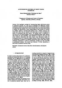
schedule has been generated and is being executed on the shop floor. Figure 1 shows the components and intercomponent data flow of the reactive scheduling system. Following is a brief discussion of the functional responsibilities of each of the components.
Schedule
Work Orders Dispatcher
New Order Information
Shop floor & Data Collector
Scheduler
Status Manager
Current Shop Floor Status
Status Messages
Status Information
FIGURE 1: REACTIVE SCHEDULING SYSTEM COMPONENTS The Scheduler takes in order information and produces a schedule to be executed on the shop floor. The Dispatcher repackages the schedule into chronological lists of production orders related to each resource and manages the delivery of these packages to the appropriate resource. The Shop floor contains resources which execute the production orders to process loads into finished products. The Data Collector gathers and reports shop floor status information about loads and resources in the form of status messages. The Status Manager receives the status messages, stores the status information in a database, and provides an interface for accessing current status information from the database. The Status Manager may also monitor shop floor performance and request that the Scheduler perform a reschedule based on performance metrics. Methods for exchanging information between the functional elements of the reactive scheduling system need to be developed. The first step in this process is defining models of the information to be exchanged. This paper focuses on conceptual models for Factory Status information and Status Message information. Express-G, which is a part of the STEP standard [3], is the language used to develop the models.
FACTORY MODEL
STATUS
INFORMATION
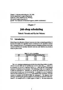
The Factory Status information model defines what is meant by status from the schedulers’ perspective. This status provides critical, dynamic information scheduling
applications need to update their simulation models in order to do reactive scheduling. Figure 2 shows the Factory Status information model. The key entity in this model is the Factory Element entity. It is an abstract supertype for the more specific entities for which status information is to be maintained. It provides for the identification and differentiation of entities in its inheritance hierarchy. There are two main subtypes of the Factory Element entity. Resource entities define information about the machines, tools, operators, and fixtures used on the shop floor. Load entities define information about the groups of parts that are processed by the resources to produce finished products. There are two kinds of attributes associated with Load and Resource entities, mutable attributes and immutable attributes. The immutable attributes are those attributes that cannot be changed after an instance is created. The type of an immutable attribute is defined as whatever is appropriate for the information that is being modeled, i.e. there is no common supertype for immutable attributes. The immutable quality of these attributes refers only to their static nature with respect to instance creation, not to their associated type. Immutable attributes were used to model things such as the type of a resource and the product that is to be the outcome of processing a load. Mutable attributes of Load and Resource entities differ from the immutable attributes in several ways. First, mutable attributes may change their value after their enclosing entity instance is created. The type of a mutable attribute must be a subtype of the Mutable Attribute Type entity. Subtypes of the abstract Mutable Attribute Type entity exist to allow the specification of attribute values for any attribute type that needs to change after the entity is created. The types of mutable attributes are all related to a common ancestor, while the types of immutable attributes are not. In the message information model that will be discussed in the next section, Create Load and Create Resource message entities specify the values needed for the creation of Load and Resource entities (the actual attribute definitions have been elided for brevity). Change Load and Change Resource message entities specify modifications to Load and Resource entities. Mutable Attribute Types, which are indirectly aggregated within the Change Message entities, are used to specify the new values for changed attributes. This ensures Change Message entities will only contain information appropriate for making modifications to the Factory Element entities while still allowing the changes to be specified in a flexible manner.
Resource_Type
Id
Resource_Type
Related_Order Related_Product Due_Date Release_Date
Start_Amount
(ABS) Factory_Element
Resource_Group Current_State Previous_State
Time_of_Last_Update Estimated_Downtime
Resource
Jobstep_Start_Time Actual_Start_Date Current_Jobstep
Associated_Load
Resource_ Status_MAT
Load_MAT
String_MAT
Associated _Value
Associated _Value
Load
Associated_Value Resource_Usage Last_Product Produced
Resource_Status
Uptime
Timestamp_ MAT
Associated _Value
(ABS) Mutable_Attribute _Type
Associated _Value
Current_State Previous_State
Elapsed_ Time_MAT
Pieces_Complete Current_Amount
Integer_MAT
Load_Status _MAT
Associated _Value
Load_Status
Associated _Value
FIGURE 2: FACTORY STATUS INFORMATION MODEL
STATUS MODEL
MESSAGE
INFORMATION
This model defines elements and relationships for Factory status messages, which are the means through which modifications to elements conforming to the factory status information model are specified (see Figure 3). The key entity in this model is the Factory Status message entity. It is an abstract entity which relates message information with the factory element that is to be modified. A timestamp attribute is used to indicate the chronological order of a group of messages. There are three main subtypes of the factory status message entity: create message entities, change message entities, and delete message entities. Each message entity subtype has been further specialized into lower level subtypes. Instances of the lower level subtypes are restricted to data relating to only one of the factory element entity types. A delete message entity specifies a request to delete the associated factory element instance. A create message entity specifies a request to create a new instance of a factory element based on the supplied immutable attribute values (The complete definition for the delete and create message subtypes have been elided for brevity.) A Change Message specifies a request to change one or more of the mutable attributes of an instance of a factory element. Associated with a Change Message is a set of Attribute Value Pair entities. These entities specify the name of the mutable attribute of a factory element to be changed and the new value for that attribute. To
ensure only valid combinations of attribute names and new values are specified, subtypes of the abstract Attribute Value Pair entity are defined with “constraints”. These constraints restrict instances to information pertaining to either Load entity mutable attributes or Resource entity mutable attributes. In a similar manner, subtypes of the abstract Change Message entity have been defined which restrict the associated Attribute Value Pair entities to the subtype appropriate for the associated factory element.
MODEL DEVELOPMENT ISSUES The Factory Status and Status Message information models were developed as conceptual models to support the development of different implementations of reactive scheduling systems. Systems based on these models have been developed using different commercial scheduling systems, data collection systems, and data storage mechanisms. In some systems, discrete event simulation systems have been used to simulate the function of the real shop floor and data collector. These models have provided ample support for research and for developing reactive scheduling applications while not restricting implementation alternatives [4]. The philosophy used in the development of these models was not to attempt to develop one monolithic model of factory information, but to focus on describing the minimal information necessary to support a reactive scheduling system by maintaining and communicating
Factory.Factory _Element
Affected_Element
(ABS) Change_ Message
(ABS) Factory_Status _Message
Timestamp
(ABS) Delete_ Message
Attributes_to_Change S[1:?]
(ABS) Create_ Message
Attribute_Name *Change_ Load _Message
*Change_ Resource_ Message
Attribute_New_Value
Factory.Mutable _Attribute_Type
(ABS) Attribute_Value _Pair
*Load AV_Pair
*Create_ Load_ Message
*Create_ Resource_ Message
*Resource AV_Pair
FIGURE 3: STATUS MESSAGE INFORMATION MODEL status related information. When an existing application is used as one of the functional elements of a reactive scheduling system, the application already contains an internal representation of shop floor information. Therefore, instead of developing models to replace the internal representations used by functional elements, models which facilitate the communication of common information between functional elements are what is needed. This is why entities for order, product, and process plan information are not defined in these models. Such information is often defined internally to the functional elements and only a means for identifying and communicating this information is required. Vendors and potential users were involved in defining the requirements for and in the development of the models since their beginning. Their domain expertise has been invaluable for ensuring that the models would be useful not only for research but also for supporting the development of real applications attempting to solve the problems of today’s manufacturers. Vendor involvement had the potential to introduce several model development risks. Care had to be taken to keep the requirements for the models from being tailored as just extensions to the vendors’ current products. Having multiple vendors and potential users involved, and developing the models as conceptual models has mitigated this risk.
CONCLUSION The Factory Status and Status Message information models provide support for the development of reactive scheduling systems. These conceptual models allow for the communication of factory status information while not
limiting implementation choices. These models are a work in progress, but several implementations have already been developed based on these models. Continued vendor and user involvement in development of these models should lead to reactive scheduling systems that aid manufacturers in increasing the efficiency of their shop floor operations.
ACKNOWLEDGMENTS Work described in this paper was sponsored by the U.S. Navy Manufacturing Science and Technology Program and the NIST Systems Integration for Manufacturing Applications (SIMA) Program. The work described was funded by the United States Government and is not subject to copyright.
REFERENCES [1]P. Timmermans, “Modular Design of Information Systems for Shop Floor Control”, Ph.D. dissertation, Eindhoven University of Technology, 1993) [2]D. Bedworth, M. Henderson, P. Wolfe, “ComputerIntegrated Design And Manufacturing”, (New York: McGraw-Hill, 1991) [3]ISO 10303-11:1994, Product Data Representation and Exchange -- part 11: Express Language Reference Manual, International Organization for Standardization, (Geneva, 1994) [4]A. Jones, F. Riddick, L. Rabelo, “Development Of A Predictive-Reactive Scheduler Using Genetic Algorithms and Simulation-based Scheduling Software”, Advanced Manufacturing Processes, Systems, and Technologies Conference Proceedings, AMPST96, 1996, 589 - 598.