Noname manuscript No. (will be inserted by the editor)
Modular Artifact Synthesis from Domain-Specifc Models †
Raphael Mannadiar and
†,‡
Hans Vangheluwe
Received: date / Accepted: date
Abstract Domain-Specific Modelling reduces the gap between problem domain and solution domain. It supports modelling using constructs familiar to experts of a specific domain. Domain-Specific models (DSms) are (semi-)automatically transformed to various lowerlevel artifacts including configuration files, documentation and executable programs. Although various aspects of model-driven development have been investigated, such as model versioning, debugging and transformation, relatively little attention has been paid to formalising how artifacts are synthesised from DSms. State-of-the-art approaches rely on ad hoc coded generators which essentially use modelling tool APIs to programmatically iterate through internal representations of DSm entities to produce target-platform artifacts. In this work, we propose a more structured approach to artifact generation where layered model transformations are used to modularly isolate, compile and re-combine various concerns within DSms, while maintaining traceability links between corresponding constructs at different levels of abstraction. We study and demonstrate how our approach simplifies addressing non-functional requirements (e.g., timing and resource utilisation constraints) of modern embedded systems. This is achieved through the modular synthesis of performance models from DSms. We illustrate our work by means of the synthesis of fully functional Google Android applications, performance predictions, simulations and performance measurement facilities from DSms of mobile phone applications. †
McGill University 3480 University Street, Montr´ eal, Qu´ ebec, Canada E-mail:
[email protected] · ‡ University of Antwerp Middelheimlaan 1, 2020 Antwerpen, Belgium E-mail:
[email protected]
Keywords Multi-paradigm modelling, Model transformation, Domain-specific modelling language semantics, Application synthesis, Performance model synthesis, Google Android Platform
1 Introduction Domain-Specific Modelling (DSM) allows domain experts to play an active role in development efforts. It provides them with means to manipulate constructs they are familiar with and to automate the many errorprone and time consuming translation steps that characterise code-centric development efforts. Most notably, the gap between the problem and solution domains is bridged. Automated transformation of Domain-Specific models (DSms1 ) to complete artifacts (e.g., executable programs, analysis models) becomes possible thanks to the tightly constrained nature of Domain-Specific Modelling Languages (DSMLs). This, as opposed to the general purpose nature of UML, for instance, which is used to model programs from any domain using objectoriented constructs. Empirical evidence reports increases in productivity of up to one order of magnitude when using DSM as opposed to traditional code-driven development approaches [34,22,32]. Due to the very central role played by automatic artifact synthesis in DSM, structuring how DSms are transformed into artifacts is both beneficial and necessary. To this day, the prevalent approach to artifact synthesis from DSms is to programmatically manipulate internal model representations and generate text – often code – [34,22]. Notwithstanding the fact that this approach contradicts Model-Driven Engineering (MDE) 1 Note that we refer to Domain-Specific Modelling as DSM and to a Domain-Specific model as a DSm.
2
principles [8], it is also riddled with flaws. Firstly, the resulting generators are often conceptually very distant from the models they “compile”. This causes their maintenance (e.g., as a result of meta-model evolution) to be tedious, complex and error-prone. Furthermore, implementing “advanced” features which require oneor two-way communication between model and artifact (e.g., model animation as a result of artifact execution) adds considerable accidental complexity [7] to the generators – which in turn worsens their maintainability – [41]. Another inconvenience of these hand-coded generators is that, due to their low-level nature and structure, they are difficult to study and analyse. Artifact generators should be anything but difficult to understand as they encode no less than the semantics (or meaning) of the DSms themselves. As such, ensuring their correctness and efficiently communicating their inner workings (e.g., among project team members) are high priorities. In short, the traditional approach makes the very crucial semantics of models difficult to debug, maintain and understand. To address the aforementioned issues of poor maintainability, poor extensibility and low abstraction, we propose that artifact synthesis from DSms be carried out via visual rule-based graph transformations, that iteratively isolate and project tangled concerns within DSms onto appropriate lower-level modelling formalisms as an intermediate step to final artifact generation. The first of our two main contributions lies in this novel approach to artifact synthesis. The second lies in the study and demonstration of how the approach can be used to elegantly and modularly replicate numerous performance assessment activities such as performance analysis, simulation and testing. The rest of this paper is structured as follows. In Section 2, we review related work. In Section 3, we introduce our approach to artifact synthesis. In Section 4, we study and demonstrate how our approach simplifies the addressing of the characteristic non-functional requirements (e.g., timing and resource utilisation constraints) of modern embedded systems. Finally, in Section 5, we discuss future work and provide some closing remarks. 2 Related Work In this section, we review relevant research on two topics: artifact synthesis from DSms, and the integration of performance concepts in the early stages of development. These topics are not as unrelated as they may seem: performance models generated from higher-level application or domain-specific models can themselves readily be considered as artifacts.
†
Raphael Mannadiar and
†,‡ Hans
Vangheluwe
Most of current research in the general area of MDE focuses on enabling modellers with development facilities equivalent to those from the programming world. Most notably, these include designing (or editing) [14, 8,6], differencing [2,11,26], evolving [10] and debugging models [41]. Another vast branch of research is that of model transformation. MDE principles state that model transformations are the preferred means of synthesising arbitrary artifacts (whatever these may be) from models [8], and considerable efforts have targeted the development and study of graphical and textual model transformation languages and tooling [1,13,36,37,39]. However, very few researchers, other than Levendovszky et al. in [25], have reported the use of model transformations for artifact synthesis in industrially relevant contexts. Indeed, another approach is favoured in most of the works that have explored the complete DSM development process starting from the design of DSMLs to the synthesis of target platform artifacts from instance DSms. In these endeavours, DSms are systematically transformed to target platform artifacts by means of ad hoc hand-coded text generators [34,22,32]. A shortcoming of this technique is that there is limited support for model and generator debugging, model animation (e.g., as a result of artifact execution), or any other activity where it may be desirable and/or necessary to have traceability links between corresponding constructs at the DSm and artifact levels. In [41], Wu et al. recognised this need for traceability in the context of DSm debugging, and proposed to augment DSm-toartifact code generators with facilities to compute and store mapping information from model to code during code generation. In their work, they demonstrate how such information is both necessary and sufficient to enable common debugging activities such as setting and clearing breakpoints and stepping into statements at the DSm level. Limitations of their work include the fact that the mapping construction inevitably introduces considerable accidental complexity into the code generator, and that the said mapping is not readily presentable to the modeller. In [40], Tawhid and Petriu review past and current research on the benefits of elevating performance concerns to the early stages of development of Software Product Lines (SPLs) and propose means to realise the said elevation. Their technique consists in annotating UML models with information that enables their subsequent transformation into performance models. These performance models lend themselves to analysis and can be used to produce performance predictions. The reasoning behind integrating low-level nonfunctional requirement related concepts so early on is that it is best to realise that these requirements cannot
Modular Artifact Synthesis from Domain-Specifc Models
be met by means of the current design early on in the development process. This reasoning is shared by numerous other authors in the performance engineering community. In [5], Becker et al. present an approach that makes use of MDE techniques to enable performance predictions in the context of component-based software engineering. The Palladio Component Model is a meta-model that allows for performance-relevant information to be specified on models of componentbased systems. For instance, a component’s time and/or resource requirements can be parametrised by probability mass functions of the input sizes (e.g., number of entries, number of kilobytes) of its arguments. From a network of parametrised components, their framework can produce performance predictions with associated probabilities. Their framework also makes use of model transformations to synthesise basic simulations which issue synthetic demands on resources. In [21,20], Kapova et al. further combine MDE and SPL techniques. In their approach, target platforms are described by feature diagrams. Then, selected features in these diagrams are used to configure model transformation rules that refine application models with target platform specifics. These refined application models are in turn transformed into performance models, which are themselves used to obtain performance predictions. In sum, considerable attention has been paid to the manual and (semi-)automated enhancement of software models with performance-relevant information, and the automatic synthesis of performance models and predictions. A crucial problem remains however: the level of abstraction of the development process remains fixed at or near the solution domain. Indeed, although certain performance- and platform-relevant details are hidden from developers, the fact remains that these developers work with code and models of code. This contradicts both the DSM and Multi-Paradigm Modelling [15] philosophies which promote development using constructs and entities from the problem domain rather than the solution domain. The approach we present in this work addresses the limitations of current artifact synthesis methods, and enables the synthesis of performance predictions, simulations and measurement facilities from domain-specific models.
3
tion of Concerns (SoC) principles dictate that modularity (and its numerous derived benefits) can be achieved by minimising the entanglement of concerns. Although the problem domain (and thus its model) should arguably not be altered and/or polluted by accidental complexities in the name of these principles, the specification of DSm-to-artifact “synthesis engines” can indeed be made more modular by their application. The SoC principles are at the core of the approach presented in this section. We propose to isolate and project the various concerns that make up a domain (and by extension its associated DSML and DSms) onto appropriate lower-level formalisms as an intermediate step to target platform artifact generation. Thus, the complete transformation of DSms into artifacts is composed of numerous modular sub-transformations, each focusing on a single concern. We detail and demonstrate our approach in an example-driven manner, describing how DSms of mobile phone applications are iteratively and modularly transformed into intermediate representations, and eventually into fully functional Google Android applications.
3.1 PhoneApps: A multi-concern DSML
3 Structured Artifact Synthesis
A typical mobile phone application combines three core concerns. The first is its visual interface, which is essentially described by the placement of widgets on the various screens the user must interact with. The second is its behaviour, which is described by the timed (e.g., a welcome screen that disappears after two seconds) and user-prompted (e.g., the click of a button) transitions between the aforementioned screens. The third (and perhaps most domain-specific) encompasses features and functions specific to mobile phone applications (e.g., sending text messages). A DSML for mobile phone applications should capture these three concerns at an appropriate level of abstraction, as does the PhoneApps DSML2 . Its meta-model is shown in Fig. 1. Essentially, timed and user-prompted transitions describe the flow of control between Containers – that can contain other Containers and Widgets – and Actions – mobile phone device specific features (e.g., sending text messages, dialing numbers) – with each screen in the final application modelled as a top-level Container (i.e., a Container contained in no other).
It is not uncommon for various concerns (e.g., layout, behaviour, performance) to be tangled within a problem description or domain. Consequently, DSMLs, whose core purpose is to enable modelling of problem domains, will often reflect this entanglement. The Separa-
2 The PhoneApps meta-model is heavily inspired by the meta-model for modelling mobile phone applications presented by Kelly and Tolvanen in [32, 22]. Our new contribution lies in the means used to produce artifacts from PhoneApps models rather than in the definition of the language’s meta-model.
†
4
Raphael Mannadiar and
†,‡ Hans
Vangheluwe
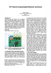
Fig. 1: The PhoneApps meta-model (as a UML Class Diagram). Without a means to transform DSms into target platform artifacts, they can only serve as blueprints and documentation. The traditional approach to artifact synthesis – which is also the one chosen by Kelly and Tolvanen to produce artifacts from DSms for their version of the PhoneApps DSML – to achieve this transformation is via hand-crafted text generators. In our approach however, a series of rule-based graph transformations “compile” PhoneApps models into increasingly lower-level (i.e., closer to code) formalisms until a complete Google Android application is synthesised. Fig. 2 depicts the relationships between the involved formalisms, with arrows between them designating model transformations. Note that the three intermediate formalisms onto which PhoneApps models are projected reflect the three domain concerns. As depicted in Fig. 2, projecting the three constituting concerns tangled within PhoneApps models produces disjoint instances of different formalisms, and as such, the order in which these projections take place is of no consequence. The formalisms and transformations introduced in Fig. 2 are described the following sub-sections, and more detailed descriptions are provided in a technical report [28]. Note that the PhoneApps DSML is one of many possible DSMLs for modelling mobile phone applications. Some alternatives may include provisions for us-
Fig. 2: Formalism Transformation Graph [15] for PhoneApps.
ing touchscreen gesture, gyroscope and camera data via new modelling constructs, others may be tailored towards very specific application domains (e.g., health care, social computing) and include higher-level abstractions3 , finally others may require lower-level concepts such as communication protocols to be exposed. In either case, new model transformation rules and/or entire 3 We demonstrated this in [16] where we built SecureApps, a DSML for modelling privacy preserving applications. We later transformed SecureApps models into PhoneApps models (which were thus at a lower-level of abstraction) as an intermediate step to artifact generation.
Modular Artifact Synthesis from Domain-Specifc Models
model transformations may be required to isolate and compile added concepts and concerns.
5
NAC
RHS
c1
3.2 Isolating behaviour
c1
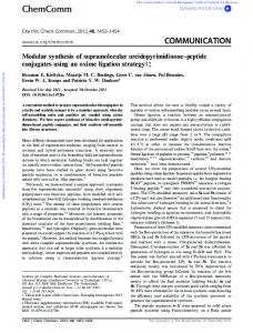
The behaviour of a mobile phone application is inherently state-based: control flows between disjoint application screens. In the PhoneApps DSML, these states are modelled as ExecutionSteps, and the flow between them is fully described by event- and timeout-triggered transitions. Thus, a natural mapping exists between the behaviour described by a PhoneApps model and a Statechart4 model [17]. Thus, the “first” step in the synthesis of executable applications from PhoneApps models is the isolation of their behavioural components and their subsequent projection onto a behaviourally equivalent Statechart model. This task is accomplished by the PhoneApps-to-Statechart model transformation. Fig. 3 shows one of the three rules 5 that form the PhoneApps-to-Statechart transformation. It depicts a PhoneApps Container and its equivalent in the Statechart formalism. A NAC is used to ensure that each Container is mapped to only one Statechart State. The edge between the Container and the State is a traceability link that explicitly captures the correspondence between them. The numerous uses of keeping such traceability information were introduced in Section 2 and are further developed in Section 3.6. When the full PhoneApps-to-Statechart transformation has run its course, every PhoneApps Container and Action has a corresponding Statechart State. These are connected via customised Statechart Transitions in a manner that reflects the edges that connect their corresponding Containers and Actions. Traceability links connect each construct in the generated Statechart model with its corresponding construct in the PhoneApps model. A key point of interest here is that no information pertaining to the placement of widgets
LHS
s1
s1.name = c1.ID c1
Fig. 3: A PhoneApps Container mapped to its behavioural equivalent Statechart State.
Fig. 4: The AndroidScreens meta-model (as a UML Class Diagram). within the Containers or to Action parameters appears in its Statechart representation: the PhoneAppsto-Statechart transformation truly projects only the behavioural concerns of the source model. Finally, although the proven and studied Statechart formalism is indeed an appropriate target formalism in this context (i.e., for the modelling of reactive statebased behaviour), it may not be optimal for or even capable of capturing other systems’ behaviour. For instance, for a traffic network DSML describing the nondeterministic flow of vehicles across connected road segments, it may be more appropriate for behaviour to be mapped onto a formalism such as Petri Nets [33].
4
Note that the current range of possible behaviours of PhoneApps models requires only the expressiveness of timed automata. Future work might extend the formalism with notions of hierarchy and concurrency such that more powerful Statechart features (e.g., orthogonality, nesting) become required. 5 Rules are the basic building blocks of rule-based graph transformations. They are parametrised by a Left-Hand Side (LHS) and Right-Hand Side (RHS) pattern, an optional Negative Application Condition (NAC) pattern, condition code, and action code. The LHS and NAC patterns respectively describe what sub-graphs should and should not be present in the source model for the rule to be applicable while the RHS pattern describes how the matched LHS pattern should be transformed by its application. Further applicability conditions may be specified within the condition code while postapplication actions may be specified within the action code.
3.3 Isolating layout The layout concern of a mobile phone application is captured by widget placement within application screens. In the PhoneApps DSML, screens are modelled as toplevel Containers, and widgets as Widgets. The formalism we introduce as a target for the projection of the layout concern is AndroidScreens. Its meta-model is shown in Fig. 4. Essentially, Screens are connected to snippets of Google Android-specific code (e.g., XML layout code, event listener Java code, etc.). The layout semantics of PhoneApps models are fully encompassed within the contents and parameters of
6
†
Raphael Mannadiar and
†,‡ Hans
Vangheluwe
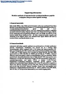
Android API calls that enact the mobile phone aptop-level Containers. Fig. 5 shows an abridged verplication functionality modelled in the corresponding sion of one of the rules that form the PhoneApps-toPhoneApps Action. AndroidScreens transformation. It depicts the extraction of the layout-relevant information found within a PhoneApps Container, and its storage into appropriate constructs of the AndroidScreens formalism. A NAC is used to ensure that the rule is only applied once for each Container. The edges between the Container and the AndroidScreens constructs once again capture corFig. 6: The PhoneFeatures meta-model (as a UML respondence information. Class Diagram). When the full PhoneApps-to-AndroidScreens transformation has run its course, top-level Containers each have corresponding Screens. These are connected to appropriately parametrised instances of AndroidCode sub-types. Traceability links connect each construct in 3.5 Merging intermediate representations the generated AndroidScreens model with its corresponding construct in the PhoneApps model. Note that no inA side-effect of our approach of projecting DSms onto formation pertaining to the behaviour of the PhoneApps various intermediate representations, is that these promodel appears in its AndroidScreens representation. Injections eventually need to be reconciled to produce the deed, the parametrised transitions that connect PhoneApps final target platform artifacts. This is especially releExecutionSteps have been stripped away by the provant when certain constructs in the DSm are mapped jection onto the AndroidScreens formalism. Nevertheto constructs in more than one intermediate represenless, the generated Statechart model produced by the tation, as is the case in our running example. PhoneApps-to-Statechart transformation is not entirely Following the mindset of easing the specification of semantically disjoint from the generated AndroidScreens traceability links between DSm and artifacts, we intromodel produced here: they are linked through the topduce a final intermediate formalism, AbstractFiles, as level Container which is mapped to both a Statechart a target for the merging of the generated Statechart, State and AndroidScreens Screen. The resolution of AndroidScreens and PhoneFeatures models. This trivthese “correspondences” will be discussed in Section 3.5 ially simple formalism merely serves as an abstraction when the three intermediate representations of PhoneApps of files on disk. Its sole construct, the ModelledFile models are woven back together into target platform arentity, has two attributes, filename and contents, and tifacts. its mapping to physical files on disk is straightforward. Hence, rather than output the results of the merging process directly to files, they are first stored as an in3.4 Isolating mobile phone device features stance model of the AbstractFiles formalism. Beyond the eased maintenance of traceability links between the Features specific to mobile phone applications include ModelledFiles that make up the generated Abstractmaking phone calls, sending text messages and launchFiles model and their source constituents (i.e., model ing native smartphone applications such as browsers. entities from the three intermediate representations), Although there are many more such features, in its curan added benefit of this design choice is that the genrent state, our PhoneApps DSML only supports these three. They are respectively modelled by the SendMessage, erated contents for each (future) file can be reviewed from within the modelling environment as part of the DialNumber and ViewWebPage constructs. The formaldebugging process. This, as opposed to having to locate ism we introduce as a target for the projection of this generated files on disk, opening them in a separate edfinal concern is PhoneFeatures. Its very simple metaitor, and possibly having to return to the model editor model is shown in Fig. 6. Essentially, Features are to perform changes. Note that if a finer level of traceparametrised by a code attribute and are optionally ability is required, contents may be an instance of an connected to a Permissions construct, which describes explicitly meta-modelled programming language. the permissions (e.g., access to the contacts list, access to geographic position) required by the Feature. A sensible and generic approach to take for the reOnce the PhoneApps-to-PhoneFeatures transformation alisation of the merging process is for the intermediate has run its course, each SendMessage, DialNumber and representation that captures behaviour to become the ViewWebPage construct has an associated PhoneFeamain executable artifact. This artifact should be intures Feature, with its code attribute set to Google strumented to make appropriate use of artifacts that
Modular Artifact Synthesis from Domain-Specifc Models
NAC
7
LHS
RHS
GenContent
GenContent
c1
c1 SetContent
event listener
...
SetContent
c1
event listener
...
Fig. 5: Extracting information from a Container into new AndroidScreens constructs. capture other concerns. Thus, in the PhoneApps example, the first step of the merging process is for the entryAction attribute of every Statechart State to be populated with method calls that execute the rendering of a Screen (renderScreen ScreenID()) or the execution of a Feature (runFeature FeatureID()) depending on if that State corresponds to a PhoneApps Container or Action. Next, a Statechart compiler is used to produce efficient and correct Java code from the Statechart model. The third and fourth steps are the transformation of the AndroidScreens and PhoneFeatures models into Statechart-oblivious target platform code. The former transformation is two-fold. First, each Screen produces a ModelledFile containing XML code that embodies widget placement. Second, a Java method, renderScreen ScreenID(), that carries out widget content and event handler setup is appended to another ModelledFile, M . The XML and Java code are both constructed from the contents of AndroidCode constructs associated to the Screen. As for the transformation of PhoneFeatures models, each Feature results in a Java method, runFeature FeatureID(), populated with the contents of that Feature’s code attribute. These generated methods are also appended to M .
to ensure that the rule is only applied once for each Screen. The entire process of artifact synthesis from DSms has been introduced. Tangled concerns within DSms are isolated and projected onto lower-level (i.e., closer to code) formalisms in a modular fashion. Then, the generated instances of these intermediate formalisms are woven back together to reflect the semantics of the source DSm. Finally, the result is output to disk to form the target platform artifacts. Moreover, the many model transformations involved leave behind a network of traceability links between corresponding constructs at different levels of abstraction, from DSms to target platform artifacts (and back). The following sub-section details the benefits of our approach over the traditional text generator approach to artifact synthesis. 3.6 Benefits of Modular Artifact Synthesis
The motivations for our approach were the need to address the poor maintainability and extensibility of hand-crafted text generators, as well as to raise their low level of abstraction. In the following, we explain how our approach improves on text generators in these three areas. The most important advantage of our approach is Once the Statechart-to-AbstractFiles, AndroidScreensthat it raises the level of abstraction and modularity of to-AbstractFiles, and PhoneFeatures-to-AbstractFiles have “artifact synthesis engines”. Whereas in the traditional run their course, a number of ModelledFiles have been approach, their development includes interaction with generated. One of them contains the compiled Stateinternal model representations and the writing of comchart model, another contains layout and mobile phone plex code, in our approach, the task of implementing feature methods, the remainder (one for each AndroidApps an artifact generator is reduced to specifying relatively Screen) contain XML layout code. The final step of simple (graphical) model transformation rules that inthe artifact synthesis process is for physical files to be teract with model entities as they are presented to modoutput from these ModelledFiles. After compilation, ellers. Furthermore, the layered nature of our approach these can be loaded onto a Google Android-enabled de(i.e., the existence of intermediate representations bevice. tween DSm and artifacts) enables low-level (e.g., target platform) details to be hidden within lower-level transOne of the AndroidScreens-to-AbstractFiles rules is formations (i.e., intermediate representation to artifact shown in Fig. 7. It depicts the creation of an Abstracttransformations). This, as opposed to their inclusion in Files ModelledFile that holds the XML layout specihigher-level, DSm to artifact transformations. fication of an AndroidScreens Screen. A NAC is used
†
8
NAC
LHS
Raphael Mannadiar and
†,‡ Hans
Vangheluwe
RHS
s1
s1
s1
x1
x1
f
f.filename = s1.ID+".xml" f.contents = x1.code
Fig. 7: The creation of one ModelledFile per Screen to hold its XML layout specification. The second benefit is that the multiple intermediate layers between DSm and artifact provide a means to observe models from various viewpoints. For instance, in the context of DSms of mobile phone applications, to study only the behavioural aspects of a model, one may study the generated Statechart model in isolation from the DSm and the other generated artifacts. More generally, a developer who wishes to focus his attention on a single concern without being distracted by irrelevant (from the point of that concern) details can easily do so. This would be an arduous task in the traditional approach where no intermediate representations are available. The remaining benefits of our approach result from the network of traceability links it creates between corresponding constructs at different levels of abstraction. In the past, the generation of such traceability information was included within existing text generators, thereby reducing their modularity and polluting them with added accidental complexity. In contrast, our approach performs the complex task of maintaining correspondence links between DSms and synthesised artifacts by explicitly connecting higher-level entities to their corresponding lower-level entities in transformation rules via generic edges. These edges have minimal impact on the readability of the rules – one could even argue that they improve their readability by clarifying correspondences – and their specification can be automated. The first of many “advanced” tasks that are made possible by traceability links is DSm animation as a result of artifact execution. Basic commands can be exchanged between synthesised artifacts and the model editing tool. These can then be propagated up the network of traceability links and animate the model. In our example, the entry into an application screen (which amounts to the entry into a compiled Statechart State) can produce the highlightSource command. Once received by the model editor, the corresponding AndroidScreen Screen, PhoneApps Container and Statechart
State are highlighted, with each correspondence resolved by navigating the network of traceability links. We have prototyped this in our implementation of the running example in AToM3 [14]. A single transformation rule suffices to instrument the entryAction attribute of generated Statechart States with the means to send commands to the model editor. This rule can easily be enabled or disabled and does not affect any of the other rules. Thus, its impact in terms of accidental complexity is minimal. Another “advanced” task that is greatly simplified by the presence of traceability links is the debugging of DSms and of model transformations. In [30], we discussed how advanced debugging facilities could be built on top of traceability links. The seamless two-way communication between DSm and artifact that they enable can assist in such debugging tasks as stepping through the execution of DSms, setting breakpoints at various levels of abstraction, and propagating meaningful exceptions from executing artifacts back to modellers. We also explored how the debugging of model transformations could benefit from traceability links. In particular, the presence of clear links that depict “what is generated from what” greatly facilitates the debugging of faulty transformation rules. This is considerably more modular and elegant than the alternative: lacing a coded text generator with output statements and/or breakpoints. Last but not least, although in a finished product the inner workings that synthesise artifacts from DSms should be hidden from the modeller, it may be useful for didactic purposes to see how higher- and lower-level constructs are related. Both our simple and modular transformation rules and the cross-level links they produce make these relationships explicit.
4 DSms and Performance Concerns The approach to artifact synthesis we presented in the previous section can also be instrumental in the con-
Modular Artifact Synthesis from Domain-Specifc Models
text of modelling (and synthesising) embedded software. More specifically, it helps address non-functional requirements. Keeping with our running example, although the Google Android platform abstracts away numerous traditional embedded systems concerns such as task scheduling, PhoneApps models remain models of embedded system applications. Thus, timing and resource utilisation information may be relevant and even required by modellers. More generally, there are numerous scenarios where domain-specific modellers may require information regarding the performance 6 of artifacts synthesised from their models. A common codecentric approach for the addressing of this need is for model transformations to refine annotated software models into performance models from which simulations and performance predictions are produced. The application of DSM principles, and specifically of the approach to artifact synthesis presented in the previous section, can improve that technique in at least three ways. First, in our approach, application models (i.e., DSms) are no longer polluted with performance-related annotations. Instead, this information is fully encapsulated in model transformations that produce platformspecific performance models from DSms. Moreover, like the PhoneApps-to-Statechart and PhoneApps-to-AndroidScreens transformations, which project only concernrelevant information onto their targets, only concernrelevant information is projected onto generated performance models. This, as opposed to performance models in the code world, which combine performance concerns and business logic. Second, one of the key differences between DSM and traditional code-centric development is that the former enables full code generation (as opposed to code skeletons). Consequently, performance models generated from DSms can not only be used to produce simulations and performance predictions. They can also be further integrated into the artifact generation process to instrument target platform artifacts with performance measurement facilities. This integration and instrumentation is analogous to the merging of intermediate formalisms discussed in Section 3.5. Revisiting our running example, the entryAction and exitAction attributes of compiled Statechart States can be augmented with performance measurement facilities to compute the time and resources consumed by the system in each State. These facilities could also include means to communicate their results back to the model editor (and the modeller). Indeed, the process of performing DSm animation by propagating commands up along the network of traceability links described in Sec6 We use the term performance loosely to represent time and other resources “consumed” by an application.
9
tion 3.6 can be used to propagate performance measurements back to any of the intermediate representations and to the DSm7 during artifact execution. In practice, this might result in model entities being “tagged” with performance measurements, and even flagged as not meeting modeller-specified performance requirements, during run-time. Third, the aforementioned instrumentation of artifacts may also assist in the arduous task of model calibration, a prerequisite to the synthesis of platformspecific performance models. This task consists in determining a platform’s performance parameters (i.e., the time and resource consumption associated to various activities) such that a realistic platform model may be produced (as shown in Table 1). Target-platform artifacts augmented with performance measurement and reporting facilities can be used to measure the performance of arbitrary tasks (e.g., the loading of a screen with x widgets), and thus to construct such platform models. Hence, in our DSM-based approach, model calibration is reduced to the creation of trivial DSms where tasks of interest are modelled, and to the collection of the performance metrics reported by automatically synthesised and instrumented target-platform artifacts. A high-level representation of the above in the context of our running example is presented in Fig. 8 which features new formalisms and transformations. These are explored in detail below. AndroidPerformanceModel is introduced as a new intermediate formalism between PhoneApps models and Google Android applications8 . Fig. 9 shows a simple meta-model for performance models. ResourceConsumers are interconnected via ResourceConsumerConnectors. These are parametrised with a probability attribute that defines the probability that the flow of control moves between the ResourceConsumers they connect. These probabilities can be set to realistic values (as opposed to their default values) by the modeller such that performance predictions have realistic associated probabilities9 . In practice, these probabilities might reflect the fact that certain use cases are more probable than others. Finally, non-functional requirements are modelled via ResourceConsumptionConstraints. These may be explicitly associated with specific ResourceConsumers, or implicitly associated to all of them (if they are not 7 Conceptually, it may however be ambiguous or confusing for performance related information to be displayed in any representation other than the generated performance model. 8 The dashed transformation arrow from AndroidPerformanceModel to AbstractFiles indicates that the generated application does not need to be instrumented with performance measurement facilities for it to function. 9 Augmenting performance predictions with probabilities was borrowed from Becker et al.’s work [5].
†
10
Raphael Mannadiar and
†,‡ Hans
Vangheluwe
Fig. 8: An updated Formalism Transformation Graph for PhoneApps.
Fig. 9: The AndroidPerformanceModel meta-model (as a UML Class Diagram). connected to any of them). This enables the modelling of local (e.g., maximum resource usage for one component of the application) and global (e.g., maximum resource usage for the full application) requirements. Note that in our running example, performance requirements are defined at the level of abstraction of performance models (i.e., in AndroidPerformanceModel entities). A more principled approach might be to extend the PhoneApps DSML itself with one or more construct to specify these requirements. This is especially sensible for contexts where performance is a “domain concern”: in such cases, it would arguably be non-domainspecific to force modellers to interact with a generated intermediate representation rather than with DSms for performance-related matters. Hence, PhoneApps Actions and top-level Containers could be augmented with attributes pertaining to their maximum allowed resource consumption. Their mapping onto equivalent ResourceConsumptionConstraints would then be carried out by an appropriately altered version of the PhoneApps-toAndroidPerformanceModel transformation. The AndroidPerformanceModel formalism is at the heart of the new transformations introduced by Fig. 8. PhoneApps-to-AndroidPerformanceModel is the first. One of its rules is shown in Fig. 10. It depicts the pro-
jection of a top-level PhoneApps Container onto an AndroidPerformanceModel ResourceConsumer, with a NAC ensuring the rule is only applied once per matching Container. The contents of the generated ResourceConsumer are abridged in the interest of brevity. They are defined using target platform information regarding time and resource consumption of various activities, as shown in Table 1. For instance, the loadingTimeRange attribute will reflect the time range required for a Google Android device to load the number of widgets present in the corresponding Container and populate them with modeller specified data. When the PhoneAppsto-AndroidPerformanceModel transformation has run its course, each PhoneApps ExecutionStep has an associated ResourceConsumer. These are connected via ResourceConsumerConnectors in a manner that reflects the transitions between corresponding Containers. From AndroidPerformanceModel models, any one of the three general performance assessment methods may be carried out. Namely, analysis, simulation and testing 10 . Performance analysis statically computes metrics from performance models. In our example, it is cap10 A thorough comparison of the pros and cons of these different methods is provided in [5].
Modular Artifact Synthesis from Domain-Specifc Models Function
Tap Touch Screen Load Screen Send SMS Send Email Load Web Data Load Local Data
11
Execution Time Range (s)
Battery Usage Range (%)
[0.001, 0.003] [0.05, 0.07] ∗ nb widgets [0.1, 0.3] + [0.1, 0.2] ∗ ⌈sms.length ÷ 120⌉ [0.05, 0.1] ∗ ⌈msg.length ÷ 1024⌉ data.size ÷ 200 Kb s data.size ÷ 5 Ms b
[0.0001, 0.0003] [0.001, 0.003] ∗ nb widgets [0.01, 0.03] ∗ ⌈sms.length ÷ 120⌉ [0.05, 0.07] ∗ ⌈msg.length ÷ 1024⌉ b data.size ÷ 50 M % b data.size ÷ 500 M %
Table 1: Synthetic performance specifications for Google Android devices.
NAC
RHS
LHS
RHS
LHS r.batteryUsageRange = ... r.loadingTimeRange = ...
Fig. 10: Populating a ResourceConsumer with information from a top-level Container. tured by the AndroidPerformanceModel-to-Performance Metrics transformation. First, it extracts every possible path between the ResourceConsumers corresponding to the starting and finishing PhoneApps ExecutionSteps. Then, for each path, resource consumption metrics and probabilities are computed by summing the resource requirements of all nodes (i.e., ResourceConsumers) and multiplying the probabilities of all edges (i.e., ResourceConsumerConnectors) along the path. This “cumulative” approach to estimating a path’s resource consumption is not unlike that presented in [9,31], where general equations are introduced to compute performance metrics of various component compositions. Fig. 11 shows the two rules that make up the path extraction portion of the AndroidPerformanceModel-to-Performance Metrics transformation. The top rule initializes the traversal algorithm. The second, which annotates a ResourceConsumer with all currently known paths reaching it, is iteratively re-applied until a fixed-point is reached11 . In the end, the ResourceConsumer corresponding to the finishing PhoneApps ExecutionStep is annotated will all possible non-cyclic paths reaching it. Although performance analysis in general is powerful due to its 11 Note that, in the interest of brevity, the expression that captures fixed-point verification is omitted from the rule’s condition code.
Fig. 11: A rule-based implementation of a path extracting graph traversal algorithm.
exhaustive nature, it can become impractical (and even infeasible) as the number of possible usage scenarios (or paths) of a system grows. Our approach does not (and can not) escape this reality, and as such, as the number of ResourceConsumers increases, the number of paths may become intractable. Simulations enable arbitrary execution paths to be observed and others to be ignored. In the code-centric development world, simulations are commonly generated from software models refined with performance annotations, with missing business logic captured by synthetic workloads. To capture a system’s behaviour at an appropriate level of abstraction, with a focus on time and resource-usage, the DEVS (Discrete EVent system Specification) [38] formalism is often appropriate. For the purpose of this work, DEVS is similar to Statechart, with a different kind of modularity, tailored for simulation. The key benefits of producing DEVS mod-
12
els rather than coded approximations of a system are essentially the same as those discussed in Section 3.6. In our running example, the synthesis of DEVS models for simulation is performed by the AndroidPerformanceModelto-DEVS transformation, whose description we omit due to its similarity with the PhoneApps-to-Statechart transformation. The third and last performance assessment method is the testing of (nearly) completed products. Their performance is often measured through code instrumentation with measurement facilities. In our running example, this weaving 12 of measurement facilities is captured by the AndroidPerformanceModel-to-AbstractFiles transformation. A simplified version of one of its rules in shown in Fig. 12. It depicts the aforementioned weaving of performance measurement and reporting facilities within the generated Statechart via instrumentation of State entryAction and exitAction attributes. A key point of interest is that a ResourceConsumptionConstraint also participates in this instrumentation: if the timing constraint described by the modelled requirement is not satisfied, the corresponding ResourceConsumer entity will be “tagged” with a red performance metric rather than a green one. Thus, another benefit of our DSM-based approach is that it enables models of non-functional requirements to be meaningfully included into the artifact synthesis process. Note that “global only” performance measurements may be compared to “global and local” measurements to ascertain the performance footprint of the woven measurement and reporting facilities. We have discussed how three common performance assessment methods, each of which is instrumental in the development of modern embedded systems applications, are supported by our approach to artifact synthesis. For each method, our DSM-based approach improves upon its state-of-the-art siblings in the codecentric development world. We now further evaluate our approach by reviewing how performance analyses, simulations and measurement facilities would be produced using the traditional coded text generator approach to artifact synthesis from DSms. The task of generating performance metrics from DSms (i.e., carrying out performance analysis) is analogous to that of generating any other artifact. Thus, the traditional coded generator approach would programmatically iterate over model entities to produce desired output, conceivably with a coded version of the traversal algorithm depicted in Fig. 11. Augmenting existing 12 The term “weaving” is borrowed from the AspectOriented Programming [23] world due to certain similarities between aspect weaving and our instrumentation of the compiled Statechart.
†
Raphael Mannadiar and
†,‡ Hans
Vangheluwe
code generators to produce such performance metrics would increase their accidental complexity and further reduce their modularity. Additional instrumentation to add performance measurement and reporting facilities into target platform artifacts, or to produce coded simulations or DEVS models would either result in considerable code duplication, or in further loss of modularity. Thus, although coded generators can replicate the three performance assessment methods – after all, anything can be programmed –, doing so would considerably hamper their modularity and/or maintainability.
5 Conclusion and Future Work Our work is motivated by the numerous shortcomings of the traditional approach to artifact synthesis from DSms. Indeed, the programmatic manipulation of internal model representations to produce target platform artifacts is at too low a level of abstraction. This makes them difficult to reason about, maintain (e.g., as a result of meta-model evolution) and extend. The approach we introduce in this paper addresses these limitations. We propose that artifact synthesis from DSms be carried out via (visual) rule-based graph transformations that isolate and project tangled concerns within DSms onto appropriate lower-level modelling formalisms as an intermediate step to final artifact generation. This approach has numerous benefits, including a considerable raise in the level of abstraction of artifact synthesis engines, which increases their accessibility and eases their maintenance and extensibility. It also greatly facilitates the maintenance of traceability information between corresponding constructs at different levels of abstraction. This information is instrumental in enabling “advanced” tasks such as DSm and model transformation debugging, and DSm animation (as a result of artifact execution). Additionally, our approach contributes to the area of embedded system applications modelling (and synthesizing) and, more specifically, in the addressing of their characteristic non-functional requirements. Indeed, the discussed benefits of structuring artifact synthesis are not restricted to coded application synthesis. They also apply to the generation of performance models from DSms, and of performance predictions, simulations and measurement facilities from performance models. We demonstrated our technique by detailing the synthesis of fully functional Google Android applications from DSms, and by replicating three common performance assessment methods (i.e., analysis, simulation and testing). Note however that although our case study is bound to the Google Android platform, our
Modular Artifact Synthesis from Domain-Specifc Models
NAC
13
RHS
LHS
c1
Fig. 12: A generated Statechart State instrumented with performance measuring and reporting facilities. approach is not. Despite the fact that some of the presented model transformations would indeed need to be refactored if the targeted platform were to change (e.g., to Apple iOS), their essence and purpose would be left intact, with each one isolating (or merging) a single concern onto lower- and lower-level representations. Finally, despite its advantages, our technique still has the unfortunate drawback that it requires a considerable amount of (non-trivial) manual work: the semantic mapping of DSms to artifacts still needs to be specified manually. This implies that DSML designers must manually identify which portions of their languages to project onto which lower-level formalisms, how to carry out the said projections, and how to merge their results back into coherent artifacts. Our current [27] and future work revolves around the (semi-)automation of this process. For instance, combining an explicit DSML concept generalisation relationship (e.g., “A PhoneApps ExecutionStep is a Statechart State”) with higherorder transformations13 allows for the automation of much of the above work (e.g., part or all of the PhoneAppsto-Statechart transformation can be generated automatically). 13 Transformations that take other transformations as input and/or outputs.
References 1. Aditya Agrawal, Gabor Karsai, Sandeep Neema, Feng Shi, and Attila Vizhanyo. The design of a language for model transformations. Software and Systems Modeling (SoSym), 5:261–288, 2006. 2. Marcus Alanen and Ivan Porres. Difference and union of models. In Unified Modeling Language (UML), volume LNCS 2863, pages 2–17, 2003. 3. Colin Atkinson and Thomas K¨ uhne. A generalized notion of platforms for model-driven development. In Sami Beydeda, Matthias Book, and Volker Gruhn, editors, Model-driven Software Development - Volume II, pages 119–136. Springer-Verlag, 2005. 4. Colin Atkinson and Thomas K¨ uhne. Reducing accidental complexity in domain models. Software and Systems Modeling (SoSym), 7:345–359, 2008. 5. Steffen Becker, Heiko Koziolek, and Ralf Reussner. The palladio component model for model-driven performance prediction. Journal of Systems and Software, 82(1):3–22, 2009. 6. Jean B´ ezivin. On the unification power of models. Software and Systems Modeling (SoSym), 4:171–188, 2005. 7. Frederick P. Brooks. No silver bullet: Essence and accidents of software engineering. IEEE Computer, 20(4):10– 19, 1987. 8. Alan W. Brown. Model driven architecture: Principles and practice. Software and Systems Modeling (SoSym), 3:314–327, 2004. 9. Valeria Cardellini, Emiliano Casalicchio, Vincenzo Grassi, Francesco Lo Presti, and Raffaela Mirandola. Qos-driven runtime adaptation of service oriented architectures. In 7th joint meeting of the European Software
†
14
Raphael Mannadiar and
†,‡ Hans
Vangheluwe
Engineering Conference and the International Symposium on Foundations of Software Engineering, 2009.
Systems, Programming, Languages, and Applications: Software for Humanity (SPLASH). HSE-Press, B-120, 2010.
10. Antonio Cicchetti, Davide Di Ruscio, Romina Eramo, and Alfonso Pierantonio. Automating co-evolution in model-driven engineering. In Enterprise Distributed Object Computing (EDOC), pages 222–231, 2008. 11. Antonio Cicchetti, Davide Di Ruscio, and Alfonso Pierantonio. A metamodel independent approach to difference representation. Journal of Object Technology (JOT), 6:165–185, 2007. 12. Krzysztof Czarnecki and Ulrich Eisenecker. Generative Programming: Methods, Tools, and Applications. AddisonWesley, 2000. 13. Krzysztof Czarnecki and Simon Helsen. Feature-based survey of model transformation approaches. IBM Systems Journal (IBMS), 45:621–645, 2006. 14. Juan de Lara and Hans Vangheluwe. AToM3 : A tool for multi-formalism modelling and meta-modelling. Lecture Notes in Computer Science, 2306:174–188, 2002. 15. Juan de Lara, Hans Vangheluwe, and Manuel Alfonseca. Meta-modelling and graph grammars for multi-paradigm modelling in AToM3 . Software and Systems Modeling (SoSym), 3:194–209, 2004. 16. Bart De Decker, Jorn Lapon, Mohamed Layouni, Raphael Mannadiar, Vincent Naessens, Hans Vangheluwe, Pieter Verhaeghe, and Kristof Verslype (Ed.). Advanced applications for e-ID cards in flanders. adapid deliverable D12. Technical report, KU Leuven, 2009. 17. David Harel. Statecharts: A visual formalism for complex systems. The Science of Computer Programming, 8:231– 274, 1987. 18. David Harel and Hillel Kugler. The rhapsody semantics of statecharts (or, on the executable core of the uml).
28. Raphael Mannadiar and Hans Vangheluwe. Modular synthesis of mobile device applications from domain-specific models. Technical Report SOCS-TR-2010.5, McGill University, 2010. 29. Raphael Mannadiar and Hans Vangheluwe. Modular synthesis of mobile device applications from domain-specific models. In The 7th International Workshop on Model-Based
Integration of Software Specification Techniques forApplications in Engineering, LNCS 3147:325–354, 2004.
19. David Harel and Bernhard Rumpe. Meaningful modeling: What’s the semantics of “semantics”? Computer, 27:64– 72, 2004. 20. Lucia Kapova, Thomas Goldschmidt, Jens Happe, and Ralf H. Reussner. Domain-specific templates for refinement transformations. In in 1st Workshop on Model Driven Interoperability (MDI), 2010. 21. Lucia Kapova and Ralf Reussner. Application of advanced model-driven techniques in performance engineering. In 7th European Performance Engineering Workshop (EPEW), volume LNCS 6342, pages 17–36, 2010. 22. Steven Kelly and Juha-Pekka Tolvanen. DomainSpecific Modeling : Enabling Full Code Generation. WileyInterscience, 2008. 23. Gregor Kiczales, John Lamping, Anurag Mendhekar, Chris Maeda, Cristina Videira Lopes, Jean-Marc Loingtier, and John Irwin. Aspect-oriented programming. In European Conference on Object-Oriented Programming (ECOOP), volume LNCS 1241, 1997. 24. Thomas K¨ uhne. Matters of (meta-) modeling. Software and Systems Modeling (SoSym), 5:369–385, 2006. 25. Tiham´ er Levendovszky, L´ aszl´ o Lengyel, Gergely Mezei, and Tam´ as M´ esz´ aros. Introducing the VMTS mobile toolkit. In Applications of Graph Transformations with Industrial Relevance, volume LNCS 5088, pages 587–592. Springer Berlin / Heidelberg, 2008. 26. Yuehua Lin, Jeff Gray, and Frederic Jouault. DSMDiff: A differentiation tool for domain-specific models. European Journal of Information Systems (EJIS), 16:349–361, 2007. 27. Raphael Mannadiar and Hans Vangheluwe. Domainspecific engineering of domain-specific languages. In 10th Workshop on Domain-Specific Modeling (DSM). Part of
Methodologies for Pervasive and Embedded Software (MOMPES), pages 21–28, 2010.
30. Raphael Mannadiar and Hans Vangheluwe. Debugging in domain-specific modelling. In 3rd International Conference on Software Language Engineering (SLE), volume LNCS 6563, pages 276–285. Springer, 2011. 31. Daniel A. Menasc´ e, Jo ao P. Sousa, Sam Malek, and Hassan Gomaa. Qos architectural patterns for selfarchitecting software systems. In 7th IEEE International Conference on Autonomic Computing and Communication, 2010. 32. MetaCase. Domain-specific modeling with MetaEdit+: 10 times faster than UML. http://www.metacase.com/resources.html; June 2009. 33. J.L. Peterson. Petri Net Theory and the Modeling of Systems. Prentice Hall, 1981. 34. Laurent Safa. The making of user-interface designer a proprietary DSM tool. In 7th OOPSLA Workshop on Domain-Specific Modeling (DSM), page 14, http://www.dsmforum.org/events/DSM07/papers.html, 2007. 35. Andy Sch¨ urr. Specification of graph translators with triple graph grammars. In Proceedings of the 20th International Workshop on Graph-Theoretic Concepts in Computer Science, 1995.
36. Yu Sun, Jules White, and Jeff Gray. Model transformation by demonstration. In MODELS, volume LNCS 5795, pages 712–726, 2009. 37. Eugene Syriani, J¨ org Kienzle, and Hans Vangheluwe. Exceptional transformations. In International Conference on Model Transformation (ICMT), volume LNCS 6142, pages 199–214, 2010. 38. Eugene Syriani and Hans Vangheluwe. Discrete-Event Modeling and Simulation: Theory and Applications., chapter DEVS as a Semantic Domain for Programmed Graph Transformation. CRC Press, 2009. 39. Eugene Syriani and Hans Vangheluwe. De-/reconstructing model transformation languages. In 9th International Workshop on Graph Transformation and Visual Modeling Techniques (GT-VMT), 2010.
40. Rasha Tawhid and Dorina Petriu. Integrating performance analysis in the model driven development of software product line. In Proceedings of the 11th international conference on Model Driven Engineering Languages and Systems (MODELS), 2008.
41. Hui Wu, Jeff Gray, and Marjan Mernik. Grammar-driven generation of domain-specific language debuggers. Software : Practice and Experience, 38:1073–1103, 2008.