Mar 14, 1979 ... Automobiles Peugeot; Societe. Anonyme ... 320/57, 59; 363/27, 37; 318/139; 307/
46, 48. [56] ... periods of the battery and to restore to the mains the discharge
current ..... connected to a negative terminal of an operational am.
United States Patent [191 Etienne [54] DEVICE FOR SIMULATING THE
4,065,711
OPERATION OF AN ACCUMULATOR
'
1671821
Anonyme Automobiles Citroen, both
[57]
[21] App]. No.: 20,444 [22] Filed; Mar. 14, 1979 [30] Foreign Application Priority Data France .............................. .. 78 09150
320/14; 320/48;
320/59; 363/27 [58]
Field of Search ................. .. 320/2, 13, 14, 48, 61,
[56]
320/57, 59; 363/27, 37; 318/139; 307/46, 48 References Cited 5/1972 4/ 1976
current to the battery in the course of the charging periods of the battery and to restore to the mains the discharge current of the battery in the course of the discharging periods of the battery, a direct current chopper for chopping the current of the battery at an available conduction rate in the course of the simulation of the cycle of operation, a switch connected between the recti?er-inverter and the chopper and circuits for
automatically controlling the chopper, the switch and the recti?er-inverter as a function of the cycle of opera
U.S. PATENT DOCUMENTS 3,663,938 3,950,689
ABSTRACT
This device comprises a recti?er-inverter supplied with current by the mains and adapted to deliver a charging
Int. Cl.3 .................................... .. H02J 7/00
[52] US. Cl. ; ..................................
tion of the battery to be simulated.
Baer .............................. .. 320/48 Jamison ........................... .. 307/46 X
c OPPER I cguTRoU
CHARGE
MONITOR?
"15‘ ._
13
'17‘ i
r
.___.
l
T
_.l
-9-
16 Claims, 11 Drawing Figures
L
-
T f
J
l
"16' _
L...
-
-1o-
-11-
'14-
CONTROL ) CYCLING CIRCUIT
‘E‘éli'ia'll. x
SWITCH) LOGIC
\
a
‘A cum
___l
__
a .M
r w i
CHOPPER LOGIC -1
RECTIFIER/ INVERTER CONTROL
-12 *
.... .. 320/ 14
U.S.S.R. .................................. .. 320/14
Primary Examiner-Robert J. Hickey Attorney, Agent, or Firm-Burns, Doane, Swecker & Mathis
of Paris, France
Mar. 29, 1978 [FR]
Kawabata ............................ .. 320/ 14
5/1970 Fed. Rep. of Germany
547913 11/1975
Michel Etienne, Valmondois, France ‘
[7 3]‘ Assignees: Automobiles Peugeot; Societe
[51]
12/1977
Jun. 9, 1981
FOREIGN PATENT DOCUMENTS
BATTERY, IN PARTICULAR A TRACTION BATTERY FOR AN ELECTRIC VEHICLE
[75] Inventor:
4,272,716
[11] [45]
TIME BASE
+
U.S. Patent
CHARGE
moun'on?
Jun. 9, 1981
Sheet 1 of6
’
4,272,716
CHOPPER coumou.
‘17'
13
{
2
-9-
_,
-10-
-11- _
CHOPPER Loslc
w
48- _1
l
‘M
a
‘A
‘14-
‘
\
SWITCH LOGIC
RECTIFIER! INVERTER
CONTROL
-12 TIME BASE
j~
CHAR
CONTROL ) cvcuue
.
CIRCUIT
CURRENT CONTROL
6 2
1B Th1Th1Th1jTh1
1
0
Th2 new; Th2 t "
01 FIG . 3
m m m
U.S. Patent
Jun. 9, 1981
M/S M“ULT‘VIB.
20”
Sheet 2 of6
4,272,716
US. Patent
63
64
65 66
Jun. 9, 1981
Sheet 3 of6
4,272,716
U.S. Patent
Jun. 9, 1981
Sheet 6 of6
M
{
105 106108 111
A
112
l
‘
IL
T
4,272,716
52 so 53 51
J.
54
I I v.‘
.
4,272,716
1
DEVICE FOR SIMULATING THE OPERATION’OF . AN ACCUMULATOR BATTERY, IN PARTICULAR
A TRACTION BATTERY FOR AN ELECTRIC VEHICLE
'
DESCRIPTION The present invention relates to batteries, in particu
2
tion followed by a braking, with a maximum current I
circulating in the battery;v FIG. 3 is a diagram of the variation of the current of the battery in the course of the simulation of a circula tion according to the Stockholm cycle;
_ FIG. 4 is a detailed schematic of the circuit control A ling the chopper of the circuit of FIG. 1;
FIG. 5 shows the logic circuit controlling the switch
lar traction batteries for automobile vehicles, and relates .
contactors of vthe circuit shown in FIG. 1;
more particularly to a simulator of the operation of such -
FIG. 6 shows the circuit controlling the recti?er inverter of the circuit of FIG. 1;
an accumulator battery.
,
The development of accumulator batteries for elec- - , FIG. 7 shows the time base circuit of the circuit of FIG. 1; . _ tric vehicles requires means for systematically measur FIG. 8 is a diagram of the signals of the various ele ing the duration of these batteries placed under their ments of the time base circuit of FIG. 7; real conditions of use. FIG. 9 is an ‘electric schematic of the circuit supervis When the measurements relating to the operations of such batteries are carried out while the battery is placed ‘ ing the state of charge of the battery; FIG. 10 is a circuit controlling the cycling of the on an actual vehicle employed for normal traf?c circu circuit of FIG. 1, and lation, they can only constitute a checking of the behav FIG. 11 shows a circuit controlling the recharging of iour of the battery with respect to time since traffic the battery. circulation in 'a town is determined more by the inten
sity of traf?c than by the actions of the driver. The object of the invention is to remedy the afore mentioned drawbacks by providing an automatic simu lator of the operation of a traction accumulator battery on an automobile vehicle.
This simulator is adapted to reproduce the operation of a battery on the vehicle when driving and when braking with recovery of energy up to an acceptable discharge of the battery. It is moreover adapted to en
In the ensuing description, the simulator according to
the invention will be considered in the case of the carry
ing out of the autonomous cycle‘ of a traction battery
de?ned by the International Electronic Commission, termed the “Stockholm cycle”, in which the following conditions must be satis?ed:
'
Acceleration of the vehicle to 50 kph, (mean accel eration of 1.5 m/sec./sec.), speed on the level, braking ' (deceleration of ~ 1.5 m/sec./sec.), stoppage during 30 seconds, the distance travelled through being 400 m per
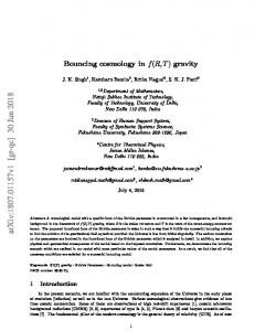
sure the recharging of the battery under given condi cycle of 70 seconds. tions, before a new discharge, the operation of the unit The simulator of the operation of an accumulator being continuous until the battery is put out of service. The device is moreover designed to place the battery 35 battery shown in FIG. 1 comprises mainly, connected to the terminals of the battery 1 to be studied, a direct under mechanical conditions which are similar to the current chopper 2, itself connected through a con actual conditions on an automobile vehicle. trolled switch 3 to a recti?er-inverter 4 supplied with According to the invention, there is provided a de current by the three-phase mains or line. The chopper 2 vice for simulating the operation of an accumulator battery comprising an electric supply device connected 40 is a circuit of the type currently employed on electric vehicles for adapting the voltage of the motor to the to a source of alternating current, wherein said supply ?xed voltage of the battery. In the present embodiment, device is formed by a recti?er-inverter supplied with the chopper 2 comprises two pairs of thyristors Th1, current by said source and adapted to deliver the charg Th2, and thl, th2 respectively connected in series to the ing current to the battery during the charging periods of the battery and restore to said source the discharging
current of the battery in the discharging periods of the battery, the simulating device further comprising a di rect current chopper adapted to chop at a variable con duction rate the current received by the battery or de
terminals of the battery 1, the junction points'of the thyristors Th1, Th2 and thl, th2 being connected to each other through a circuit comprising a capacitor C1
and an inductor Ll.
Connected to the terminals of' the aforementioned thyristors are two diodes D1, D2 in series, the cathode live‘red by the battery in the course of the simulation of 50 of the diode D1 being connected to the anodes of the an operational cycle of the battery and a switch con thyristors thl, Th1, whereas the anode of the diode D2 nected between the recti?er-inverter and the chopper is connected to the cathodes of the thyristors th2, Th2. I circuit to produce the passage of a charging current The junction pointof the diodes D1 and D2 is con from the recti?er-inverter to the battery in the course of nected to the junction point of the thyristors Th1, Th2. charging periods of the battery, and the passage of a 55 The chopper 2 just described is connected to the switch discharging current from the battery to the recti?er 3 which, in the presently-described embodiment, is an
inverter and the source during the discharging periods of the battery. Further features of the invention will. be apparent
electromechanical reversing switch comprising two coupled pairs of contacts 5, 6 respectively controlled by
relays 7,8. The moving contacts 5 and 6 cooperate re from the ensuingldescription with reference to the ac 60 spectively with the corresponding ?xed contacts the companying drawings which are given solely by way of closure of which ensures the inversion of the direction example and in ‘which: ‘ , of the current applied to the terminals of the diode D2 FIG. 1 is a synoptic schematic of a simulator of the of the chopper 2. Such an electromechanical switch is operation of a traction battery for electric vehicles vac conventional in circuits controlling electric motors and cording to the invention; 65 it may be easily constructed in the form of a semi-con FIG. 2 is a diagram, with respect to time, of the con ductor circuit. Two ?xed input contacts of the switch 3 duction times ‘of thervarious elements of the circuit of are connected to the output of the recti?er-inverter 4. FIG. 1 required to obtain the simulation of an’accelera In ‘the presently described embodiment, this recti?er
3
4,272,716
inverter is a conventional synchronous recti?er-inverter
currently employed industrially. It is a recti?er-inverter having a six-phase bridge including six thyristors con trolled by a current which is governed by a set refer ence value. It is connected to the three-phase mains or line. The simulator shown in FIG. 1 further comprises a number of means for controlling the circuits 2, 3 and 4
4
the terminal of the capacitor 30 opposed to the resistor 28 and earth.,Connected in parallel to the capacitor 30 isthe emitter-collector path of a transistor 32 whose
base is connected to the output of the operational ampli ?er 27 through a voltage divider 33, 34. The output of the operational ampli?er 29 is connected to the negative and positive inputs of ampli?ers 35 and 36 respectively. These same .inputs are moreover connected to the out
so as to permit the obtainment of a succession of simu
put of a switching circuit 37 controlled by the monosta
lated town circulation cycles until discharge of the battery 1, then the recharging of the latter under set conditions before going on to the carrying out of the
ble circuit 20. The operational ampli?er 35 is adapted to
cycles of operation. Among these control elements, there are:
a a a a
logic circuit 9 controlling the chopper 2; logic circuit 10 controlling the switch 3; circuit 11 controlling the recti?er-inverter 4; general time base;
invert the input function in such manner that there appears at its output a voltage which varies linearly between 0 and a given negative value, for example — 10
V, whereas the ampli?er 36 is adapted to deliver the 15 symmetrical function so that there appears at its output
a voltage which varies linearly from said negative value
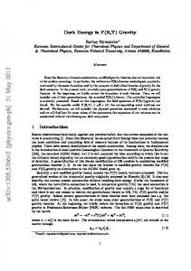
to O V. The outputs of the ampli?ers 35 and 36 are connected to an input of a summing ampli?er 38 whose output is connected to an input of a comparator 39 to a control unit 13 supervising the state of charge of the 20 which is also connected a sawtooth signal generator 40 batteryll; the amplitude of which signals is equal to the value of a circuit 4 controlling the cycling. the currents delivered by the ampli?ers 35 and 36 The logic circuit 9 controlling the chopper is con whereas the frequency is equal to a predetermined nected to the chopper 2 through a chopper control value, for example 200 Hz. The output of the compara' circuit 15. Associated with the recti?er-inverter 4 is a current 25 tor 39 is connected to a gate 41 which is adapted to deliver a signal controlling the chopper 2 and is con control circuit 16. nected to the control electrodes of the thyristors Th1 The unit 13 supervising the state of charge of the and Th2 of this chopper. ' battery comprises a circuit 17 supervising the state of The logic circuit 10 controlling the switch 3 is shown charge and a circuit 18 controlling the recharging of the 30 in FIG. 5. battery. . ' The output of the circuit 18 is connected to an input
This circuit comprises three monostable circuits 42,
43 and 44. The input of the monostable circuit 42 consti of the circuit 11 controlling the recti?er-inverter. tutes the input of the logic circuit connected to the The circuit controlling the cycling 14 comprises a corresponding output of the time base circuit 12 of FIG. start-stop output connected to an input of the time base circuit 12 and a clock output connected to another input 35 1. This input is connected to the input of the monostable circuit 43 through an inverter 44. The outputs of the of this time base circuit. The time base circuit 12 com monostable circuits 42 and 43 are each connected to an prises a ?rst output connected to the input of the logic input of an inverting AND gate 45 whose output is circuit 9 controlling the chopper, a second output con connected to the input of the monostable circuit 44. nected to an input of the logic circuit 10 controlling the inverter, a third output connected to an input of the 40 Two outputs of the monostable circuits 44 are respec tively connected to the inputs of inverting AND gates circuit 11 controlling the recti?er-inverter and a fourth 46 and 47 whose other inputs are respectively con input controlling means (not shown) for mechanically nected to the inputs of the monostable circuits 42 and vibrating the battery. 43. The outputs of the gates 46 and 47 are each con The logic circuit 10 controlling the switch 3 com prises a second input connected to an additional output 45 nected to an input of an inverting AND gate 48 whose output is connected to an assembly of gates 49 which is also connected to the corresponding output of the cir The chopper control logic circuit 9 is shown in FIG.
of the cycling circuit‘14.
The comprises a monostable circuit 20 whose input is
cuit 14‘controlling the cycling of FIG. 1. The assembly of gates 49 comprises two inverting AND gates 50, 51
connected through an inverting AND gate 21 to a trac
whose ?rst inputs are connected to the output of the
tion output T1 andlto a braking output T4 of the time base circuit 12. An jioutput of the monostable circuit 20
circuit 14 controlling the cycling. Another input of the
gate 50 is connected to the output of the gate 48 through an inverter 52, whereas the other input of the gate 51 is directly connected to the output of the gate 48. The the other input of which is connected to the terminal T4 through an inverter 23. The other output of the mono 55 output of the gate 50 is connected to an inverter 53 whose output constitutes the traction control output Kt stable circuit 20 is connected to an input of an inverting of the inverter 3, whereas the output of the gate 51 is AND gate 24 the other input of which is connected to connected to an input of an inverting AND gate 54 the terminal T1 through an inverter 25. The outputs of whose other input is connected to an inverter 55 which the gates 22 and 24 are connected to corresponding inputs of an inverting AND gate 26 whose output is 60 constitutes the control input of the inverter for charging the battery. The output of the gate 54 constitutes the connected to a negative terminal of an operational am pli?er 27 adapted to deliver at its output a positive or ' braking control output Kf of the inverter 3. The circuit 11 controlling the recti?er-inverter 4 of negative current :15 V for example, in phase opposi the simulator according to the invention is shown in tion with the input pulse. The output of the ampli?er 27 is connected, through a resistor 28, to an input of the 65 FIG. 6. This circuit comprises four input transistors 55 to 58 operational ampli?er 29 which comprises in its feedback whose bases are connected to the inputs T1 to T4 circuit a capacitor 30. Associated with the ampli?er 29 through resistors 59 to 62. The emitter-collector paths is a voltage limiting Zener diode 31 connected between
is connected to an input of an inverting AND gate 22
4,272,716
5
of each of the transistors are connected to reference
voltage circuits constituted by current dividers each . comprising a resistor 63 to 67 in series with a potentiom
eter 66 to 70. The slide of each of the potentiometers is connected, through resistors of the same value and a diode 71 to 74, tovthe input of an operational ampli?er 75. This input of the ampli?er 75 constitutes the refer
ence current'of braking traction or of recharge adapted to be applied to the circuit 16 associated with the in verter 4 through the ampli?er'75 adapted to deliver to the inverter the reference current having a correct power level.
6
put of the ampli?er 98 is connected to inputs of two
comparators 100 and 101 through respective voltage dividers 102-and 103 which are supplied with current by a constant voltage source and are respectively regulated to give voltages one of which corresponds to 80% of
the discharge of the battery and the other to 100% of
the charge of the battery. The outputs of the comparators 100 and 101 are con
nected to the corresponding inputs of the circuit 13 controlling the recharging 18 of the simulator of FIG. 1. The circuit controlling the cycling 14 is shown in FIG. 10.
-
The time base circuit 12 of the simulator of the inven- , ‘ tion is shown in FIG. 7. '
It comprises mainly a STARTswitch 104 and a STOP switch 105 which are respectively connected This circuit comprises a clock 76 whose ?rst output is through inverters 106 and 107 respectively to an input connected to a ?ip-?op GK 77, which is connected to of a NAND gate having two inputs 108 and to an input another ?ip-?op GK 78. The latter is connected to a _ of a NAND gate having three inputs 109. Another input third GK ?ip-?op 79. The non-inverting output of the of the gate 109 is connected to the charge ouput of the ?ip-?op 77 is connected directly to a NAND gate 80 supervising circuit of FIG. 9. having four inputs, to‘ an input of a NAND gate .81 20 The circuit of FIG. 10 further comprises an addi having four inputs through an inverter 82, directly to a tional input connected to the output relating to the end
third NAND gate 83 having four inputs/anddirectly to
of the charging of the supervising circuit of FIG. 9, this input being connected through an assembly of gates 110 The non-inverting output of the ?ip-?op 78 is con to the other input of the gate 108. The outputs of the nected directly to another input of the gates 80 and 81 25 gates 108 and 109 are connected respectively through and, through an inverter 85, to another input of the an inverter 111 and directly to the inputs of a NAND gates 83 and 84 and to an input of a NAND gate 86 gate 112 whose output is connected to the third input of having three additional ‘inputs. the gate 109 and constitutes, furthermore, the control The non-inverting output of the ?ip-?op 79 is con output connected to the time base circuit 12. > a NAND gate 84having three inputs.
'
nected to a third input of each of the gates 80, 81 and 83 30
and, through an inverter 87, to the remaining inputs of the gates 84 and 86.
The clock 76 further comprises a start-stop input M/A which is connected to the respective start-stop
inputs of the ?ip-?op 77, 78 and 79. This input of the clock 76 is connected to the start-stop input of the time base circuit which is itself connected to thecircuit 14
The output of the gate 112 and the output of the assembly of gates 110 are respectively connected to the common input of the gates 50 and 51 and to the input of
the inverter 55 of the logic circuit controlling the in verter shown in-FIG. 5.
The recharging control circuit 18 of the device of FIG. 1 is shown in FIG. 9.
In the presently-described embodiment, considered as being applied to a lead battery, this circuit comprises input of the time base circuit is furthermore connected two ampli?er stages 113, 114 which are connected in to an input of a NAND gate 88 whose other input con 40 cascadel Connected to one of the inputs of the stage 113 stitutes the reference stop input of the circuit. The out through a potentiometer 115 is a source of voltage put of the gate 88 is connected to the fourth inputs of which de?nes the voltage Um,“ of maximum charge of the gates 80, 81 and 83 through an inverter 89. the battery to be tested. Moreover, this same input re The invertingoutputs of the ?ip-flops 77 to 79 are ceives the instantaneous voltage U); of the battery. The respectively connected to three inputs of a NAND gate 45 output of the stage 113 is connected to the input of the 90 whose fourth input is connected to the output of the stage 114 at the output of which there are connected,'in clock 76 through a delay circuit 91. The output of the series, two identical resistors 116 and the slide of a po gate 90 is connected to each of the control inputs of the tentiometer 117 connected between a source of positive ?ip-flops 77 to 79. a voltage and earth. The junction point of the resistors The outputs T1 to T5 of the gates 80, 81, 83, 86 con 50 116 is connected to the input of the ampli?er 114 stitute the outputs of the cycle de?ned by the time base through a diode 118. The output of the ampli?er stage and connected to the logic circuit 9 controlling the 114 constitutes the output of the recharging reference , chopper, to the logic circuit 10 controlling the switch 3, current adapted to be applied to the control circuit 11 of and to the circuit controlling the recti?er-inverter. the recti?er-inverter 4. The circuit supervising the state of charge of the g The operation of the simulator of the invention will battery 1 is shown inFIG. 9. now be described with reference to, in particular, It comprises'a voltage divider 92 constituted by two FIGS. 2, 3 and 8. resistors 93 and 94 connected in series to the terminals The current of the battery of the operation of which of the battery 1. A capacitor 95 is connected in parallel on the vehicle the device according to the invention is with the resistor 94. The junction of the resistors 93 and 60 adapted to simulate, flows between the three-phase 94 is connected, through a resistor 96 and the source supply mains for the recti?er inverter and the battery 1 drain path of a ?eld effect transistor 97, to an input of an in passing through the recti?er-inverter 4, the con ampli?er 98 whose otherv input is connected to earth trolled electromechanical switch 3 and the direct cur through the source-drain path of a ?eld effect transistor rent chopper 2. 99. The gate electrodes of the transistors97 and 99 are 65 The maximum amplitude of the current of the battery connected to a reading control input of the circuit. The is always given by the current delivered by the recti?er ampli?er 98 is adapted to store the value of the voltage inverter. This current thereafter passes through the of the battery between two successive cycles. The out electromechanical switch 3.
controlling the cycling of the simulator. The start-stop
4,272,716
7i
In the case of the output of the battery corresponding to the simulatedtraction of a vehicle,‘ this current'passes
vehicle on a level and, in the course of the 10 seconds
preceding the stoppage period, there is a simulation of the braking with regeneration, that is to say restoration
through the battery I‘-‘ and returns to the ~ recti?er
inverter 4 in passing throughthe thyristor Th1 which is rendered conductive for this purpose.
8
20 seconds, there is a simulation of a travelling of the
‘
7 of a certain current to the battery.
The graph of FIG. 3 shows moreover that, during the entire part of the cycle during which there is a simula tion of the operation of the vehicle, there is also an emissionof a signal causing the mechanical vibration of
On the other hand,"when the‘battery 1 receives elec tric energy, for example in the course of the simulation of the braking of the vehicle with recovery of energy'or in the course of the recharging of the battery, the cur» rent delivered by‘ the‘ recti?er-inverterv 4 passing through the contacts 5 actuated by the relay 7 of the
the battery simulating the movements thereof ‘on an actual vehicle‘. The variation of the current of the battery in the course of a Stockholm cycle is represented by the curve
switch 3, passes through the diode D1 of the chopper circuit 2, the battery 1, and returns to the recti?er inverter 4. The recti?er-inverter 4 is employed with controlled current I which is governed by a value Ire/2 The instan taneous maximum value of the current of the battery ,is therefore ?xed by this reference current.
t
2
A and the signal for producing the mechanical vibra tions is represented by v‘the curve B.
The control of the operation of the assembly compris ing the chopper 2, theswitch 3 and the recti?er-inverter
‘i4ifor the-purposeof causing the battery to supply a
The assembly formed by the recti?er-inverter 4 and current, conforming to that shown in FIG. 2 and in the electromagnetic switch 3 is practically equivalent to 20 accordance with a cycle corresponding to that shown in a direct current electric motor operating as a motor or _ FIG. 3,,is ensured by the assembly of the circuits associ ated with the aforementioned assembly and shown in a generator, depending on whether there is a simulation the drawings. The chopper 2 is controlled by the logic of the driving or of the braking of the vehicle. control circuit shown in FIG. 4. It concerns the switch The chopper 2 operates in the following manner. .When the battery is being discharged the turning on of 25 ing on of the traction thyristor Th1 and braking thy ristor Th2 of the chopper 2.‘The logic circuit 9 receives the thyristor Th1 causes the passage of a current I
‘through the battery. The turning off of this thyristor
from the time base circuit 12 a traction order T1 emitted
causes this current I to pass through the diode D2 and consequently cancels out the current. circulating in the
applied to the monostable circuit 20 which delivers a
by the clock 76 of the time base circuit. The signal T1 is
battery. ‘The conduction and extinction times of the 30 pulse having a duration of 5 seconds. This pulse is ap thyristor Th1 consequently regulate the mean current of plied to the operational ampli?er 27 which delivers at its output a voltage signal in phase opposition.to the the battery and the mean output voltage of the recti?er input pulse. This voltage signal, whose value is for ex inverter 4. ‘ ample equal -_t- 15 V, is applied to the operational ampli When the battery 1 is being recharged, the current I normally passes through the diode D1. The ignition of ?er 29 which deliversa voltage which varies linearly the thyristor Th2 causes the passage of this current >
through thisthyristor and consequently cancels out the current circulating in the battery. The conduction and extinction time of the thyristor Th2 consequently regu lates likewise the mean current of the battery and the mean output voltage of the recti?er-inverter 4. The form of the current delivered by the chopper to the terminals of the battery 1 is shown in FIG. 2.
This Figure clearly shows the conduction times of
from 0 to a predetermined value, for example 10 V in 5 seconds, this variation being achieved by means of the RC circuit formed by the capacitor 30 and the resistor 28. The Zener diode 31 prevents the output voltage of
the ampli?er 29 from exceeding the aforementioned value of 10 V. When the output voltage of the ampli?er 27 passes to its positive value of +15 V, the transistor 32 associated with the ampli?er 29 becomes conductive and causes the quasi-instantaneous discharge of the
various elements necessary to obtain the simulation and 45 capacitor 30 while maintaining the output voltage of the acceleration followed by a braking with a maximum ampli?er 29 at zero. The output signal‘ of the ampli?er
current I circulating in the battery corresponding to the 29 is applied to the inputs of the ampli?ers 35 and 36 which operate in turn under the control of the switch‘ current delivered to the motor, or produced by the latter, on a simulated vehicle. The assembly formed by ing means 37 which releases either the ampli?er 35 or the chopper 2 connected to the terminals of the battery 50 the ampli?er 36, depending on whether-it transmits the 1, the switch 3 and the recti?er-inverter 4 must be . traction order-T1 or the braking order T4 applied to the brought into action to achieve a succession of cycles of monostable circuit 20. .
simulated town circulation, each cycle comprising peri ods of acceleration, travelling on the level, braking, stoppage, until the discharge of the battery, it being necessary to thereafter recharge the battery under im posed conditions before proceeding to another cycle.
The operational ampli?er 35 inverts the input func tion so that there appears at its output a voltage which varies linearly between 0 and a negative value 'equal to — 10 V for example. The operational ampli?er 36 deliv ers on the other hand the symmetrical function of the preceding function so that there appears at its output a
If it is assumed, as mentioned before, that the device voltage which varies linearly between a negative value, of the invention‘ is intended to simulate the circulation of a vehicle in accordance with the Stockholm cycle, 60 equal to — 10V for example, and zero. the graph of the current of the battery is given by the The summing ampli?er 38 makes the sum of the sig curve shown in FIG. 3.
.
.
»
This graph shows that the total duration of a cycle is
70 seconds, the last 30 seconds of a cycle corresponding to the stoppage of the vehicle. In the course of the,?rst 10 seconds of the cycle, there is an acceleration of the vehicle and consequently an increase in the current
supplied by the battery, in the course of the following
' nals from the ampli?ers 35 and 36 and its output voltage
is compared with a sawtooth signal of amplitude equal to the extreme values of the voltages delivered by the ampli?ers 35 and 36, that is to say :10 V and of a
frequency equal to 200 Hz. The output signal of the comparator ‘39 _is applied to the gate 41 which delivers a signal for controlling the chopper for the purpose of
9
4,272,716
causing the conduction or the blocking of the thyristors Th1 and Th2 of the latter. When the output signal of the gate 41 is equal to 1, it causes the conduction of the thyristor Th1 and when it
10
which exists from 30 to 40 sec., 21 pulse T5 which exists from 60 to 70 sec. and a short pulse T8 which appears after 70 see. so as to recommence the cycle at zero. The
start-stop signal M/A applied to the gate 88 of the time base circuit and coming from the circuit 14 controlling the cycling, ensures, when it is at level 0, the resetting of
is equal to 0, it causes the conduction of the thyristor Th2. The sequence of operation of the switch 3 is con trolled by the logic circuit 10 shown in FIG. 5. This circuit receives at a ?rst input connected to the time base circuit 12 and connected to the monostable circuit 42, a signal initiating the passage to traction of the logic level l or a signal for the passage to the brak
the three ?ip-?ops 77 to 79 and the blocking of the clock 76. When this signal passes to the state 1, the clock is started again and the counting of the divider by 7 constituted by the three aforementioned ?ip-?ops and the gate 90 starts again. ing of the logic level 0. The supervision of the state of charge of the battery At its input connected‘to the circuit 14 controlling is ensured by the circuit of FIG. 9. ‘The voltage of the the cycling, the circuit of FIG. 5 receives a start signal battery 1 to be tested supplies current to the divider 92 of a logic level 1 or a stop signal of a logic level 0. As 15 which delivers at the point of junction of the resistors 93 its input controlling charging operation, the circuit of and 94 a proportional voltage. The ampli?er 98, the two FIG. 5 receives a signal also coming from the cycling . ?eld effect transistors 97 and 99 and the capacitor 980 control circuit of FIG. 10.
connected between an input and the output of the am
When the input signal coming from the time base
pli?er 98 ensure the reading of this voltage during the
circuit 12 is a signal initiating the passage to traction, the 20 duration of the signal T1 applied to the control elec assembly formed by the monostablecircuits 42 and 43, trodes of the transistors 97 and 99 and delivered by the the inverter 44 and the gate 45, delivers a pulse having cycling control circuit 14. There is moreover a storage a width of 0.2 second which is converted by the mono of the value of the voltage of the battery which may be stable circuit 41 into a direct signal or an inverse signal read between two successive cycles at the output of the having a width equal to 0.3 second. 25 ampli?er 98. This voltage is'compared by the compara These offset pulses, processed in the gates 46, 47 and tor 100 with a voltage corresponding to the maximum 48, cause the excitation of the gate 50 and consequently contemplated discharge state embodied by the voltage the transmission of the signal Kt initiating the passage of added to the output voltage of the ampli?er 98 by a the contacts of the inverter 33 to the traction position voltage divider comprising the potentiometer 102. The with a delay of 0.3 second at the instant of application 30 signal T1 is positioned in the cycle in such manner that
by the cycling control circuit 14 of the start signal. When the time base circuit 12 applies to the circuit of FIG. 5 a signal initiating the braking, the monostable circuits 42, 43 and 44 deliver, as before, signals of 0.2 sec and 0.3 second which, through the gates 48 cause the 35
the voltage measured by the supervising circuit validly gives the discharged battery information.
application of the braking initiating signal Kf to the inverter 3 and the interruption of the signal Kt.
During the battery recharging period, the order em bodied by the signal T1 is permanent. The output volt age UBM of the ampli?er 98 follows the voltage of the battery and is then compared by the comparator circuit
In the stop position, the switch 3 is completely re
leased and in the charging position an input signal ap plied to the gate 55 permits putting the switch 3 into the same position as the braking position, that is to say
causing the closure of the contacts 6 by the relay 8 of
For example, in the case of a lead battery, the signal T1 is applied to the circuit when the simulation device has been at rest, at zero current, for 20 sec.
40 101 with a voltage corresponding to a 100% charge of
the battery delivered by the divider comprising the potentiometer 103. As soon as the recharging of the
said switch. battery has ?nished, the value of 100% is reached and The signals coming from the outputs T1 to T4 of the the comparator 101 delivers at its output a signal corre time base circuit 12 and applied to the bases of the tran 45 sponding to an order to stop ‘the charging of the battery sisters 55 to 58 of the circuit controlling the recti?er and to recommence a new simulation cycle. inverter 4 shown in FIG. 6, render these transistors The recharging control circuit of FIG. 11 receives
successively conductive and successively release the
the signals coming from the supervising circuit of FIG.
voltage references set on the potentiometers 67 to 70.
9.
Consequently, the ampli?er 75 delivers to the recti?er inverter reference currents in accordance with the se
quence de?ned by the time base circuit 12. Thus, the . current delivered by the recti?er inverter varies in ac
cordance with the pre-established cycle.
‘
As this circuit has detected the necessity to recharge the battery, the recti?er-inverter 4 delivers the current required to recharge the battery, whereas the contacts of the switch 3 are automatically shifted to the braking
position. The recti?er-inverter 4 then operates as a The time base circuit 12 shown in FIG. 7 will now be 55 charger and the reference current received by the cir
considered with reference to the diagram shown in FIG. 8. The clock 76 of this circuit delivers signals
cuit 11 controlling the recti?er-inverter is delivered by the recharging control circuit 18. Depending on the
having a width of 10 microseconds every 10 seconds as
type of battery employed, the relation battery voltage/
shown by the line H of the diagram of FIG. 8. These battery current is different. The circuit of FIG. 11 is signals are applied to the ?ip-?op J K 77 which supplies 60 intended to be employed in the case of a lead battery. current to the ?ip-?op 78 which in turn supplies current When the voltage of the battery U3 applied to the input to the ?ip-?op 79. The output signals of these three of the ampli?cation stage 113 of this circuit is lower flip~flops, which appear on the lines B1, B2, B3 of the then the maximum voltage UBmax, the output potential graph of FIG. 8, are combined by the gates 80 to 90 so of the stage 113 is positive and determined by the gain that at the inputs T1 to T5 and T8 of these gates there 65 A1 of this stage. This. positive potential gives at the appear in succession a pulse T1 which existsfrom 0 to output of the stage 114 a negative potential which is 10 sec., a pulse T2 which exists from 10 to 20 sec., a compared by the identical resistors 116 with the image pulse T3 which exists from 20 to 30 sec., a pulse T4 value Imax. The difference is applied by the diode 118 to
4,272,716
11
12
the input of the ampli?er stage 114. Equilibrium is ob tained when the reference current is equal and of oppo site sign to the maximum set reference. The recharging is consequently effected at a quasi constant voltage practically equal to the set value.
.
The cycling control circuit shown in FIG. 10 re
.
4. A device as claimed in claim 1, further comprising a control circuit connected to control the recti?er- '
inverter for causing the recti?er-inverter to deliver a current corresponding to predetermined reference cur rents in the course of the various periods of simulation
of the charging of the battery and for causing it to oper
ceives on its two contacts 104 and 105 the manual start
ate as an inverter in the course of the periods of simula
or stop orders. The gates 109 and 112 store these orders and deliver the control signals to the time base circuit 12 at the output of the gate 112. These gates moreover ensure the blocking of the switch 3 of the simulator of FIG. 1. The order to start the recharging, coming from
a logic circuit connected to the switch to control the switch as a function of the sequence of simulation of the
battery charging and discharging periods, a control
the charge supervising circuit 17 and applied to the gate assembly 110, is stored in this assembly. This gate/as
causing the recti?er-inverter to deliver a current corre
tion of the discharging of the battery. 5. A device as claimed in claim 2, further comprising
circuit connected to control the recti?er-inverter for
sembly ensures, on one hand, the control of the cycling 5 sponding to predetermined reference currents in the course of the various periods of simulation of the charg by the gate 108 and, on the other hand, the setting of the ing of the battery and for causing it to operate as an switch 3 at such position as to allow the recti?er inverter in the course of the periods of simulation of of inverter 4 to ensure the recharging of the battery. the discharging of the battery, a control circuit ensuring The simulator of the operation of an accumulator
battery which has just been described has, by its very construction, the advantage of being in the condition of permanent energy exchange with the electric supply mains or line, which consequently receives in return the simulated energies of the traction of the vehicle.
Although in the present description the simulator of the invention has been considered as being applied to an accumulator battery for the traction of an electric vehi
cle, this simulator may be used for testing accumulator batteries intended for applications which are very dif
ferent from that contemplated. For this purpose, it is suf?cient to adapt the control circuits of the simulator to the charging and discharging cycles to which the accumulator batteries are desired to be subjected as a function of their conditions of use. Having now described our invention what we claim as new and desire to secure by Letters Patent is:
1. A device for simulating the operation of an accu
mulator battery, comprising an electric supply device
the supervision of the state of charge of the battery and
a time base circuit connected between said state of
charge supervision control circuit and the logic circuit controlling the chopper, the logic circuit controlling the switch and the circuit controlling the recti?er inverter so as to ensure the sequential control of these
circuits as a function of the state of charge of the battery and manual start and stop instructions. 6. A device as claimed in claim 5, wherein said time base circuit has a traction output and a braking output,
said logic circuit controlling the direct current chopper comprises a monostable circuit having an input which is connected through a gate to the traction output and to
the braking output of said time base circuit and outputs which are each connected, through an inverting AND gate controllable by a corresponding inverted input signal, to a circuit generating a voltage which varies linearly in the course of an interval of time de?ned by
the monostable circuit and the inverting AND gates through which it is connected to said generating circuit,
for connection to a source of alternating current, said
the device further comprising two ampli?ers, switching
supply device comprising a recti?er-inverter for con
means connected to control the two ampli?ers, .the
nection to said source and for connection to the battery for delivering a charging current to the battery in the
generating circuit having an output connected to the two ampli?ers, the monostable circuit having an output
course of the battery charging periods and for restoring connected to the switching means through one of the to said source a discharge current of the battery in the 45 gates connecting the monostable circuit to said generat course of the battery discharging periods, the simulat ing circuit so as to transmit selectively the traction ing device further comprising a direct current chopper circuit adapted to chop at a variable conduction rate
order and the braking order applied to the inputs of the logic circuit controlling the chopper, summing means, a
selectively the current received by the battery and the
comparator, the ampli?ers having outputs connected
current delivered by the battery in the course of the 50 through the summing means to the comparator, the simulation of a cycle of operation of the battery, and a comparator being capable of comparing the signals of switch connected between the recti?er-inverter and the the outputs of the ampli?ers with a sawtooth signal of
chopper circuit for causing the passage of a charging current from the recti?er'inverter to the battery in the
course of the battery charging periods and the passage
amplitude equal to the amplitude of said signals and of predetermined frequency delivered by a generator.
of a discharge current from the battery to the recti?er
7. A device as claimed in claim 5, wherein the logic circuit controlling the switch comprises a ?rst monosta
inverter and the source during the battery discharging
ble circuit, a second monostable circuit and a third
periods.
monostable circuit, the ?rst monostable circuit having
2. A device as claimed in claim 1, further comprising a logic circuit connected to the chopper circuit to con trol the chopper circuit in accordance with a predeter mined sequence corresponding to a cycle of simulation that it is desired to impose on the current circulating in
an input connected to a corresponding output of the
time base circuit, the second monostable circuit having an input connected to the same output of the time base ' circuit through an inverter, and the third monostable
circuit having an input connected to outputs of the ?rst and second monostable circuits through a ?rst NAND 3. A device as claimed in claim 1 or 2, further com 65 gate, second and third NAND gates connected for combining the input signals of said ?rst and second prising a logic circuit connected to the switch to control monostable circuits with an output signal of the third the switch as a function of the sequence of simulation of monostable circuit and its opposite signal respectively, a the battery charging and discharging periods.
the battery.
13
4,272,716
fourth NAND gate connected for combining the output
14
of the control circuit for supervising the state of charge of the battery, said assembly of gates being capable of producing selectively a traction order signal and a brak ing order signal to be applied to said switch.
a delay circuit, the NAND gate having an output con nected to control inputs of the JK ?ip-?ops. 12. A device as claimed in claim 5, wherein said con trol circuit for supervising the state of charge of the battery comprises a state of charge supervising circuit, a ' circuit controlling the recharge which is connected to the state of charge supervising circuit and connected to said circuit controlling the recti?er-inverter and to a
8. A device as claimed in claim 6, wherein said circuit controlling said recti?er-inverter comprises an opera tional ampli?er, transistors, and a number of reference
circuit controlling the cycling which is connected to the time base circuit. 13. A device as claimed in claim 12,v wherein said state
voltage circuits adapted V to the number of reference
of charge supervising circuit comprises a voltage di
currents which said recti?er-inverter must receive in the course of a cycle of operation of the simulator, said reference voltage circuits being connected to the corre
vider connected to the terminals of said battery, an
11. A device as claimed in claim 10, wherein said divider circuit comprises a ?rst JK flip-flop, a second JK flip-?op and a third JK ?ip-?op connected in cas
instantaneous voltage of the battery.
signals of said second and third NAND gates, the out ' put of said fourth gate being connected to an assembly
of gates which assembly is also connected to an output
ampli?er for reading and storing ‘the voltage of the
battery between two successive cycles and having an input connected to the voltage divider, a circuit con sponding outputs of the time base circuit through corre sponding ones of said transistors and connected to an - nected for initiating said ampli?er upon the reception of a reading pulse and a unit for comparing the voltage of input of the operational ampli?er which is for sequen the battery with a voltage corresponding to a predeter tially delivering the reference currents to said recti?er 20 mined pourcentage of discharge of the battery and with inverter. a voltage corresponding to the full charge of the bat9. A device 'as claimed in claim 7, wherein said circuit tery, said amplifier having an output connected to said controlling said recti?er-inverter comprises an opera unit. tional ampli?er, transistors, and a number of reference 14. A device as claimed in claim 12, wherein said voltage circuits adapted to the number of reference circuit controlling the charging comprises a ?rst ampli currents which said recti?er-inverter must receive in ?er stage, an adjustable source of voltages de?ning the the course of a cycle of operation of the simulator, said maximum charge voltage of the battery to be super reference voltage circuits being connected to the corre vised, a current limiting circuit, and a second ampli?er sponding outputs of the time base circuit through corre stage having an output which de?nes, in combination sponding ones of said transistors and connected to an input of the operational ampli?er which is for sequen 30 with the current limiting circuit, the reference current of recharging to be applied to the recti?er-inverter, the tially delivering the reference currents to said recti?er ?rst amplifier stage having an input which is connected inverter. to the adjustable source of voltage and receives the 10. A device as claimed in any one of the claims 5 to instantaneous voltage of the battery. 9, wherein said time base circuit comprises a clock, the 15. A device as claimed in claim 13, wherein said clock having an input, the control circuit for supervis circuit controlling the charging comprises a ?rst ampli ing the state of charge of the battery having a start-stop ?er stage, an adjustable source of voltages de?ning the output connected to the input of the clock, a divider of maximum charge voltage of the battery to be super signals of the clock, and an assembly of gates for pro vised, a current limiting circuit, and a second ampli?er ducing sequentially from output signals of the divider, 40 stage having an output which de?nes, in combination signals of the clock and control signals coming from with the current limiting circuit, the reference current said control circuit for supervising the state of charge of of recharging to be applied to the recti?er-inverter, the the battery, signals for synchronizing the various cir ?rst ampli?er stage having an input which is connected cuits of the device. to the adjustable source of voltage and receives the 16. A device as claimed in any one of the claims 12 to
15, wherein said circuit for controlling the cycling com prises an assembly of gates for combining start and stop signals which it receives from manual control switches with the output signals of the circuit for supervising the state of charge of the battery for the purpose of control ling the time base circuit and controlling the logic cir
cade to the clock, said JK ?ip-?ops having inputs con nected with the input of said clock, to the start-stop control output of said control circuit for supervising the state of charge of the battery, said J K ?ip-?ops having inverting outputs each connected to an input of a
NAND gate having four inputs the fourth input of
cuit controlling the'switch.
which NAND gate is connected to said clock through
*
55
65
i
i
i
*