LMTD â Log mean Temperature Difference. TTD â Terminal .... when calculation the value for multipass exchangers correction factors also must be applied to ...
Department of Mathematics wtrnumber2013-1. Control Charts for Monitoring
Weibull Distribution. Chuanping Sze and Francis Pascual. March 2013.
May 30, 2012 - ABSTRACT. Enel Distribuzione and Siemens are developing a new system called âMAGOâ (Monitoring and control of. Active distribution Grid ...
medical support and heat injury assessment and management where ... (5) Practice the buddy system to monitor performance
medical support and heat injury assessment and management where tactically .... example, on a sunny calm day an open fie
Mar 7, 2003 - (I) Convection is heat transfer by moving a gas or I iquid over the ..... This zone of elevated steady-sta
Monitoring & Control. Today's market and its evolution till 2020. Final Report of
the Study. SMART 2007/047. Edited by: Jorge Pereira, EC ...
Keywords: Thermal Infrared; LANDSAT ETM+; ASTER; Sea Surface ... the Enhanced Thematic Mapper Plus (ETM+) on the LANDSAT -7 satellite, launched.
Monitoring and reporting of accurate temperature control. Application description
... Food Safety (Temperature Control) Regulation 1995, all ofwhich stipulate the ...
Department of Zoology and Entomology, Colorado State University, Fort ... (Received 16 November 1983: accepted in revisedform 20 July 1984). Abstractâ1. The ratio of rates of heating and cooling in American alligators is maximum at a ...
Feb 11, 2015 - and to know their preferred sites to do their cooking. Methodology. Sample size: a .... Using communal ki
Jan 11, 2015 - (ICLA + Social) with taking Gender into consideration. ... 3%. Opinion on Distribution mechanism. Good. F
neuro-fuzzy control of the heat exchanger is compared with classical PID control. ..... Kakac S., 2002, Heat Exchangers: Selection, Rating, and Thermal Design, ...
flow in a heat exchanger or to phase changes (e.g., condensation) or to other ... transfer, our intuition will be aided by noting also that this same equation.
Giuma M. Fellah, Yamen Abdelwhab, and Faraj Aljtilawi. Department of Mechanical and Industrial Engineering. Faculty of Engineering, Al-Fateh University.
Polymer electrolyte fuel cell (PEFC) has been developing as clean power generation .... production rate of i-th species in gas phase, kg/(m3ã»s). 2. .... 0.199. 0.199 - 0.319. 0.140. 0.199. Stoichiometric Ratio [-]. 1.43. 1.43 - 2.33. 1.00 ... The c
Industrial Process Applications ... In this paper, an intelligent information management and control system is ... Many research studies, which proposed different combinations of systems theoretic and artificial intelligence ..... companies was estab
Jul 18, 1996 - nies, building management rms, et al. ... analyzing, and acting upon energy end-use data ... available through Energy Management Control ..... Ryerson Polytechnic has developed a Unix-based ..... manual intervention. ... 12 trol system
Barbara Hayes-Roth, Richard Washington,. Rattikorn Hewett ... We thank Edward. Feigenbaum for ... Hayes-Roth, Washington, Hewett, Hewett and Seiver. 243 ...
In addition, the POMDP framework has a number of ... itoring phase runs continuously, with the control phase ..... There is a great deal of work in POMDPs and.
firmly stays in the space of distributions and their intrinsic âdiffeologyâ, in particular avoiding to view distributions as generalized functions. We describe in Section ...
run control, fault detection and classification, metrology data monitoring. 1. ... ficient operations, minimize downtime of equip- ment, and optimize the yield of high ...
Aug 25, 2013 ... USP 36. Table 4. A Two-Row by Two-Column Contingency Table with .....
General Information / 〈1116〉 Aseptic Processing Environments 787.
Data acquisition and monitoring unit (Main Server). It is a ... possible to exchange data with other control and data acquisition systems using open interface ...
International Carpathian Control Conference ICCC’ 2002 MALENOVICE, CZECH REPUBLIC May 27-30, 2002
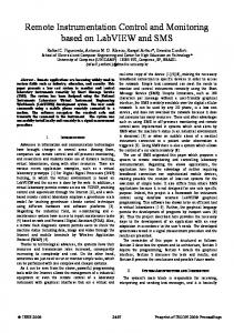
MONITORING AND CONTROL OF HEAT DISTRIBUTION Wojciech GREGA1 and Krzysztof KOŁEK2 Department of Automatics, University of Mining and Metallurgy, 30-059 Kraków, Poland, Al. Mickiewicza 30, 1 [email protected], [email protected] Abstract: This paper presents a control and monitoring system for the heat distribution network servicing the buildings of the University of Mining and Metallurgy (AGH) campus in Kraków. The system has a multi-layer structure and integrates several state-of-the-art technologies and standards applied in modern industrial automatics. Key words: Supervisory control, heating system control, optimization, telemonitoring,
1 Introduction Energy consumption for heating purposes accounts for a significant part of the budgets of individual and collective users. This increases the importance of issues related to the monitoring of heating energy flows, analysis of flow parameters, verification of fees and, in the first place, minimization of energy consumption. Adequate control of energy consumption and distribution is one of the most significant means of power consumption optimization, besides methods such as thermal insulation of buildings, etc. Modern heating systems tend to apply automation of the processes of energy production, delivery and control of recipient substations [KRZYZAK 1999]. Recent developments in microprocessor technology and industrial IT tools created new possibilities in the areas of access to real-time information about the operating parameters of a heating system and fast data processing. The application of modern telecommunication and computer technologies allows effective transfer of operating data even within the entire territory of a city. There are new concepts such as „telemonitoring”, „telecontrol”, or „virtual enterprise” [GREGA 1999] reflecting the trends related to the integration of geographically scattered and functionally different systems of automated control, production management and planning into one consistent system with unrestricted information flow between particular components. This has opened new possibilities for optimum delivery and distribution of heating energy but, on the other hand, set new 439
challenges related to the search for new control concepts and methods. The fact that the depreciation of investments made to modernise automated control systems and establishment of a heat distribution monitoring and optimization system can be achieved in a relatively short time through reduction of the power charges is an additional motivation. The system of automated control implemented in the heating system supplying the group of buildings of the University of Mining and Metallurgy (AGH) campus in Kraków is a typical example of such a project. During the heating season of 2000/2001 the buildings were consuming up to 20 GJ/h. Such a high power consumption allows significant savings if a proper control strategy is implemented. The heating system of the AGH campus became the focus of the “System for monitoring and optimization of heat energy consumption in AGH” project implemented in years 2000/01. The key objectives of the project were: • to develop a system allowing control and monitoring of the operations of a heating substations being part of the AGH power and heat supply system, • to identify ways to optimise energy consumption and develop adequate control algorithms.
2 Integrated Control and Monitoring System The main AGH campus heating substation (MHS) supplies heat and hot water to a group of 16 lecturing, administration and laboratory buildings. It is composed of a set of
IPC-CHIP
G10 substation
CO
alarms SMS
other users (students, reseaches..)
Internet
SCADA: iFIX system
operators
Backup Server (data analysis)
Main Serwer IPC-CHIP
B6 substation
CO
CAN fieldbus
PLC2 controller
PLC1 conroller
distance substations
sensors
B1 building
valves
sensors
pumps
Meteo station
CO CW U O
Main heating substation
Figure 1. Structure of the AGH heat distribution control and monitoring System 440
heat exchangers with a total capacity of app. 8 MW, fitted with pumps, expansion vessels and a heating water treatment plant. The substation’s throughput accounts for app. 70% of the total heating energy consumed. Seven smaller distance substations supply remaining university buildings are located up to 2,5 km from the MHS. They are equipped with local systems control controlling the energy inflow. The developed system of control and monitoring has a multi-level structure. It consists of the following levels (Figure.1): Direct control and data gathering level collecting information from the MHS (Main Heating Substation) and from some substations located in a close distance to MHS. The key elements of this layer are PLC controllers equipped with local industrial network interfaces (CAN fieldbus) [LORENZ 1997]. The tasks occurring at this level consist of regular readouts of the substation operating parameters. It also carries out the base tasks of direct process control: stabilization of temperatures in the heating and service water installations, follow-up tracking of changes in outdoor temperature, detection and signalling of exceeded substation operating parameters. Data acquisition and monitoring unit (Main Server). It is a high-parameter PC-class computer serving as a platform for the SCADA industrial operating system. The installed iFIX system [WWW.INTELLUTION] performs tasks that are typical for a power dispatch unit – acquisition of substations operating data to the databases, visualization of the process status as well as detection and reporting of emergency conditions. The example of the operator screen available through the main server is shown in Figure 2. The main server is also used as a supervisory control platform changing reference temperature values in the particular installations. The iFIX system communicates, via Internet, with the heat supply control Figure 2. Visualization of the MHS operating parameters systems in distance buildings, using novel technology of modular IPC-Chip network servers [KOLEK 2002].
441
Backup server – generates and stores backup copies of databases, performs data analyses and provides access to substation operating data to all Internet users (see: http://wg.ia. agh.edu.pl) The suggested structure of the system meets the key requirements of modern remote control and monitoring systems. The system is scalable and open, meaning possible optional addition of subsequent controllers to the implemented CAN network. The preparation and wiring covers an area of app, 1.5 km2. If necessary, it will be possible to add new embranchments to the network, reaching the most remote buildings. It will also be possible to exchange data with other control and data acquisition systems using open interface standards. The “open” character of the system software allows easy modification, including addition of new procedures used in various research projects and experiments.
3 Direct Control Optimal control of a heating system should aim at minimizing the difference between the current demand for heating energy and the supply. Hot heating water supplied by the MPEC (Municipal Power and Heating Company) plant (app. 110ºC) transfers the heat to an internal heating installation (flow of over 600 t/h) and service water installations. The demand depends, in the first place, on the Main Serwer outdoor temperature Głó and time of the day or T , T ............ season but also on the accumulation Tfxo Fxo capacity of the heating W Tprof Supervisory control Tw system. The required temperature of the Trefco heating water (Tfxo in R1 Figure 3) can thus be Tzm Tzco determined based on CH O outdoor temperature information. After Trefzwu T1prof MPEC application of a AGH correcting factor (the R2 value of the factor –central heating Tzwu depends on the applied CH HSW – hot service water HSW supervisory control method for Tprof) this temperature is then Figure 3. Direct and remote control of water flow in the heating and service water systems being compared to the temperature of the water supplying the buildings, and the deviations are being minimized by controller R1 regulating supply to the heat exchangers on the MPEC side. A similar control structure has been applied in the service water supply system. 4 0 3
4 0 3
IPC-CHIP
b1
IPC-CHIP
·
b2
IPC-CHIP
b
)
%
442
The above control scheme is commonly applied in the automated control of local substations supplying individual buildings. However, the size of the AGH campus and the area covered by the heating network cause additional complications. For example, changes in flow on the supply side of the heat exchanger result in uneven changes in heaters’ temperature (after a few minutes in rooms directly adjacent to the substation and up to an hour later in more remote points of the network). The temperature of the supply water (and thus the available heating capacity) on MPEC side may change up to 30% within 12 hours, along with stochastic changes in supply pressure. If the heat supply control system has to take into account the fact that some of the buildings are only used in specific times of the day and that standard thermal comfort has to be reinstated in working hours, it becomes clear that there is need for non-conventional supervisory control methods, based on a model of the system. The control sequences (Tprof in Figure 3) introduce a supervisory correcting factor for the preset temperature, depending on the time of the day and year, outdoor and indoor temperatures and the measured or calculated current energy consumption in individual buildings (Wb in Figure 3). Selection of the adequate time sequence of changes in preset temperature results in more or less significant power savings. Inadequate application of this scheme may, on the other hand, cause energy losses. Control of the heating system circulation pumps is also related to the profile of the preset temperature Trefco. When the building indoor temperature gets close to the outdoor temperature (it often happens at the end of heating season), power consumption goes down approaching zero. In such a situation, pumping can be reduced or the pumps may get shut down. This task is being performed by the PLC2 controller (Figure 1).
4 Supervisory Control The core principle of the energy saving algorithm is based on lowering the night-time temperature and increasing it in the morning, taking into account the weather/temperature profile. Decrease in temperature results in Power saved [GJ/h] energy savings. Increasing the 20 temperature causes energy losses but reinstates thermal comfort in the heated 15 facilities. The main disturbances observed in the system influence hot heating water 10 tempertaure supplied by the MPEC ( Tzm (t ) ) and outdoor temperature 5 (+) ( Tw (t ) ). More precisely, the optimal supervisory control problem was formulated as follows. Using the models of the energy consumption and prediction of Tzm (t ) and Tw (t ) find the optimal function Tprof.(t) such that:
0
(-)
-5
-10 0
1
2 3 4 5 2001.01.28 00:00 - 2001.02.03 23:59
6
7
Figure 4. Example of weekly operation energy saving profile
443
•
the consumption of the energy is minimized in the time period [t 0 , t 2 ] : t2
min WCO (t )dt , where WCO (t ) is the power temporary consumed by the heating system.
∫
t0
•
the avarage termal comfort in the buildings is restored at the end of the period :
(Tˆwew − Twew (t 2 )) ≤ ε , where Tˆwew - desired temperature in the rooms.
Figure 4 shows the power savings profile, being the difference between hypothetical power and real consumed power (2001.01.28 to 2001.02.03). During the night-time temperature reduction, the power saving has a positive value. Part of the saved energy is used during the morning overheating. The saving/loss balance is positive, achieved energy savings amount to 300 GJ. To calculate a hypothetical power consumption (and finally, power savings) a neural network based model was developed [Grega, Kolek 2001].
5 Conclusions The applied control system and supervisory control algorithms do result in power savings. Initial evaluation indicates that the investments in implementation of this project got depreciated through reduced heating bills during the 2000/2001 heating season. Analysis of long-term data and improvement of supervisory control algorithms may become a potential source of further savings. The implemented hardware and software configuration represents state-of-the-art concepts and technologies applied in industrial control. Internet access to substation operational parameters and data established the foundation of a virtual research and teaching laboratory, allowing verification of research results on an industrial-type process.
Acknowledgements This paper was supported by the UMM research grant.
References KRZYŻAK W., LICHOTA J. 1999. Zastosowanie sztucznych sieci neuronowych do sterowania sieciami ciepłowniczymi, Prace XIII Krajowej Konferencji Automatyki, pp. 195-198, GREGA W. 1999. Sterowanie cyfrowe w czasie rzeczywistym. Wyd. Wydz. EAIiE AGH, Krakow 1999, ISBN 83-907546-9-X LAWRENZ W.1997. CAN System Engineering, Springer, 1997, ISBN 0-387-94939-9 WWW.INTELLUTION.COM/PRODUCTS/FIX KOLEK K, BANIA P. 2002. Internetowy system pomiarowy (Internet measuring system), Pomiary, Automatyka, Robotyka, no.2, 2002, pp.5-8 GREGA W. KOŁEK K. Sterowanie nadrzędne węzłem cieplnym (Supervisory control of heat center), Pomiary, Automatyka, Robotyka, no.7/8, 2002, pp.18-24