MPPT Schemes for Single-Stage Three-Phase GridConnected Photovoltaic Voltage-Source Inverters Emad M. Ahmed3) Masahito Shoyama1) Gamal M. Dousoky1,2) 1) Kyushu University, 744 2-626-1 motooka, nishi-ku, Fukuoka, 819-0395 Japan 2) Minia University, Alminia, 61517 Egypt 3) Aswan University, Aswan, Egypt E-mail:
[email protected] Abstract- Single-stage grid-connected PV systems provide many advantages such as simple topology, high efficiency, high power density, and lower cost. However, achieving MPPT, while conditioning the output power and synchronizing with the power grid, is a big challenge in such systems. In this paper two MPPT schemes are investigated for single-stage three-phase gridconnected photovoltaic voltage-source inverters. MPP is tracked using either the load angle or the inverter modulation index. A theoretical framework of the schemes is provided. Furthermore, a simulation model is developed in MATLAB Simulink and the simulation results are presented in this paper. Then the schemes are implemented using a fixed-point digital signal processor (DSP) TMS320F2812. Moreover, a breadboard circuit is built-up for investigating the effect of the proposed schemes on MPPT in a single-stage three-phase grid-connected photovoltaic voltage-source inverter. Furthermore, a comprehensive discussion is carried-out to evaluate the performance of each scheme. The experimental results show that both schemes can track the maximum available power of the PV. Furthermore, a hybrid scheme that employs both schemes may be a good compromise to attain efficient dynamic and steady state performances.
I.
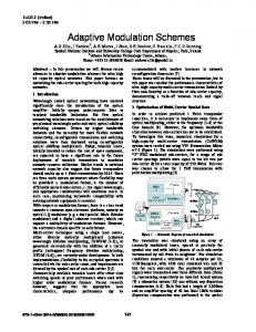
Fig. 1. A generator connected to the power grid.
the most energy is captured. MPPT is an essential part of any PV system [7]. In recent years, a large number of peak-power tracking methods have been proposed and implemented [6]– [11]. This paper investigates two MPPT schemes for singlestage three-phase grid-connected photovoltaic voltage-source inverters. Digital control is a flexible and attractive hardware design option, becoming lower cost, and getting faster. These competitive tools have made the application of many sophisticated control algorithms possible in this field [9]-[11]. The implementation of the proposed tracker has been accomplished by a fixed-point Digital Signal Processor (DSP). The paper is organized as follows: Section II presents a theoretical framework, brief description of a single-stage grid-connected PV system description, and conventional incremental conductance (INC) MPPT. Simulation results and digital implementation are addressed in section III. Section IV describes the details of the experimental setup, experimental results, and discussion. Finally, conclusions and future work have been presented in section V.
INTRODUCTION
The most relevant goals of PV energy include cost reduction of the power-converter stage, increased efficiency of both panels and converters, and considerable improvement in converter reliability [1]–[4]. Grid-connected Photovoltaic systems usually employs two stages: The first stage is a dc-dc boost converter for boosting the PV voltage, and achieving MPPT; and the second stage is a dc-ac inverter for conditioning the output power and synchronizing with the power grid. However, such systems have drawbacks as higher part count, lower efficiency, lower reliability, higher cost, and larger size [5]–[6]. On the other hand, single-stage grid-connected systems provide many advantages such as simple topology, high efficiency, high power density, and lower cost. However, achieving MPPT, while conditioning the output power and synchronizing with the power grid, is a big challenge in such systems [6]–[8]. The inverters must guarantee that the PV module(s) is operated at the MPP, which is the operating condition where
978-1-4673-4569-9/13/$31.00 ©2013 IEEE
II. THEORY AND SYSTEM DESCRIPTION A. Power injection principle In the case of a connection of an alternate current (ac) generator to the power grid, the generator output is equal to the grid voltage and the generator is the source of active power (Pge) and reactive power (Qge). Fig. 1 shows an equivalent diagram of a grid-connected generation system, and a simplified vector diagram [12].
600
1 ○
4 ○
2 ○ 3 ○
5 ○
8 ○
IPV
7 ○
6 ○
VPV δ, mi
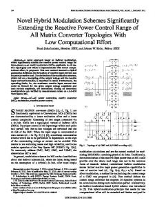
Fig. 2. Schematic diagram of the proposed single-stage grid-connected PV system.
The active power, provided by the generator can be calculated as follows: Pge = Ege Vgr sin (δ) / Xg (1)
B. Brief Description of a Single-Stage Grid-Connected PV System Figure 2 presents a schematic diagram of the proposed single-stage grid-connected PV system. This system can be briefly described in the following points:
and the reactive power: Qge = [(Vgr)2 –Ege Vgr cos (δ)] / Xg
(2)
where the voltages are expressed in rms values.
Both of δ and/or mi are employed to achieve MPPT: Extract the maximum available power from the PV panels. The control signals generator generates the reference signals at the desired δ and the desired mi. The digital pulse-width modulator generates the gate signals corresponding to the reference signals and the internally-generated triangular wave. The synchronizing unit is used to connect to the power grid only when the synchronization conditions are fulfilled.
If we have a system as shown in Fig. 2, the Photovoltaic output power can be calculated as follows: PPV = VPV × IPV
(3)
Considering a fixed hardware setup (Xg = constant), and for the purpose of maximizing the PV output power, we have two control variables: 1- The inverter modulation index (mi) that directly controls the magnitude of the inverter ac output voltage (Ege). 2- The load angle (δ); the phase angle of the sinusoidal pulse-width modulation (SPWM) control signal (w.r.t. the power grid voltage phase angle). The load angle (δ) usually has a small value. In such band of angles, the sine function has a sharp slope, and the cosine function has a flat slope. Therefore, the active power (Pge) is deeply affected by changing δ than by changing the generator output voltage (Ege; by changing mi). However, the reactive power (Qge) is deeply affected by changing Ege (by changing mi) than by changing δ. Yet the fact that either/both of δ or/and mi affects both of Pge and Qge. The above principle is usually used in case of conventional power generation systems. Moreover, it is applicable to gridconnected PV systems.
C. Conventional Incremental Conductance MPPT Incremental-conductance (INC) method [10]–[14] is based on the fact that the slope of the PV array power curve versus voltage is zero at the MPP. The INC MPPT algorithm usually has a fixed iteration step size determined by the requirements of the accuracy at steady state and the response quickness of the MPPT. Thus, a tradeoff between dynamic and steady-state responses has to be investigated at the corresponding design. The primary rules for INC MPPT algorithm are deduced as follows: the power curve of the PV module shows that the derivative of the PV module power PPV with respect to its
601
PV Voltage (V)
dI PV − I PV = dVPV V PV
PPV dI PV − I PV > dVPV V PV
50 0
PV Current (A)
dI PV − I PV < dVPV V PV
100
Decreasing δ, mi
dI PV I PV + dVPV VPV
PV Power (W)
(5)
δ (n) = δ (n − 1) − Δδ ⎫ ⎬ δ (n) = δ (n − 1) + Δδ ⎭
(6)
or applying the following rule-in case of tracking with mi: ⇒
e