Multi,Core Microprocessors in Embedded. Applications by Douglas Hamilton.
European Applications Engineering. Networking and Computing Systems Group.
Freescale Semiconductor
multicoreWP Rev. 0, 01/2005
White Paper
Multi-Core Microprocessors in Embedded Applications by
Douglas Hamilton European Applications Engineering Networking and Computing Systems Group Freescale Semiconductor, Inc.
Increasingly, semiconductor suppliers are offering dual-core microprocessors. This white paper addresses the following question: What are the key benefits driving this significant trend?
1
Introduction
Until now, Moore’s prediction that transistor density would double every year has been realized, driven primarily by the thirst for higher performance. However, the traditional approach to the development of superscalar microprocessors, where performance gain was derived largely by increasing the frequency, is failing to meet the performance and power requirements of the next generation of microprocessors. The world’s leading manufacturers are offering dual-core microprocessors to address these increasingly stringent requirements. Power consumption is especially critical for power-sensitive embedded systems, such as network communication implementations, where dual-core devices offer a favorable performance/watt trade-off. Beyond just the processing power offered by an additional core, higher integration reduces bottlenecks in bandwidth and latency. Dual-core devices are already prevalent in computationally intensive applications such as servers and workstations. But now, the embedded space is more influential in driving next-generation dual-core devices. It is also important to consider the target applications of dual-core products, both symmetric and
© Freescale Semiconductor, Inc., 2005. All rights reserved.
1. 2. 3. 4. 5.
Contents Introduction . . . . . . . . . . . . . . . . . . . . . . . . . . . . . . . . . Power . . . . . . . . . . . . . . . . . . . . . . . . . . . . . . . . . . . . . Integration . . . . . . . . . . . . . . . . . . . . . . . . . . . . . . . . . . Operating Systems and System Partitioning . . . . . . . . Dual Core Strikes the Balance . . . . . . . . . . . . . . . . . .
1 2 4 6 7
Power
non-symmetric multi-processing implementations, and to make necessary provisions in the hardware implementation to support a broad range of configurations.
2
Power
Power consumption levels are not only becoming an increasing concern in the desktop computing world, but they are also bordering on unacceptable for embedded markets. What do designers mean when they refer to power? Until now designers only had to consider the AC component when talking about a device’s power consumption. Power is consumed due to the charging and discharging of gates, as explained by the following equation: PAC = nCV2f Where, n is the fraction of active switching transistors within the device C is capacitance of all of the gates V is the transistor voltage f is the core frequency
2.1
Leakage Problems
Another component to this equation is the leakage or static power that is also commonly referred to as the DC power component. It is caused due to the leakage current present when the transistor is in an off state. It comprises two inherent transistor characteristics. The first is gate leakage, which is the tunnelling of carriers through the gate’s oxide insulator. The second is a weak sub-threshold leakage current that causes the transistor to switch on before the threshold voltage is applied. Reducing the gate width and its oxide thickness would reduce gate leakage; however, this is not an option because the critical dimensions of gate width and oxide thickness are fixed to ensure correct operating characteristics of transistors for a given process geometry. For example, a 60-nm gate width and a 1.5-nm-thick oxide, typical for 130 nm, drops to around 50 nm and 1.2 nm respectively in 90 nm. Work is underway on a next-generation 65-nm process with high-k dielectric material for gate insulators that would allow thicker layers, but these are more difficult to make than silicon dioxide layers available currently. With a high-k material, the carriers have higher mobility. But because the thickness is increased, the overall relative mobility of the carriers remains the same, so the operational characteristics of the transistor are not affected. It can be seen that the sub-threshold current decreases for increased threshold voltages. However, this increased threshold causes loss of switching speed performance that translates to a hit in terms of clock frequency. Now the equation has the significant added static component and looks like this: P = nCV2f + ILEAKAGEV Where, ILEAKAGE is the total of leakage currents present across all transistors The reduced operating voltage benefits of smaller 90-nm technology are counterbalanced by the static power, no longer negligible, because leakage currents associated with smaller geometry processes are more dominant. 90-nm leakage current is two to three times that of 130 nm at the same voltage. These increased leakage currents are worse with smaller geometry processes because shrinking the transistor reduces the distance between gate, drain, and source. As a result, tunnelling carriers meet relatively low channel resistance, increasing their mobility and Multi-Core Microprocessors in Embedded Applications Rev. 0 2
Freescale Semiconductor
Power
creating larger leakage currents. These currents generate static power components that can account for more than half of the total power in some 90-nm devices. Smart techniques are being used to minimize such static power effects. Some designers are developing high-performance processes that reduce power by reducing the supply voltage, whereas others are designing a lower-power embedded process from the ground up. The latter design exploits the static power relationship with threshold current by tightly controlling threshold voltage at the individual functional block. This approach ensures that the threshold voltage for a given block is specified according to the level of performance and hence the frequency that it requires. Silicon-on-insulator (SOI) technology offers even lower power and voltage operating conditions at higher frequencies. SOI reduces parasitic capacitance by insulating the transistors, resulting in up to 25% faster switching frequency, or as much as a 20% power reduction. These two benefits can be traded off to achieve target frequency-to-power ratios. The effectiveness of the 90-nm SOI process is seen in its AC power reduction factor of 3.38, which offsets almost exactly the leakage effects in 90 nm. The improvements in the process facilitate a reduced operating voltage and a smaller die area that is proportional to capacitance. Although a 1-GHz device may require 1.3 V in 130-nm technology, the same device in 90 nm can operate at 1.0 V. The additional die-size reduction factor of 0.5 yields the following: PAC = nCV2f ⇒ AC Power Reduction 130nm – 90nm
2.2
= (A130nm V2 130nm)/(A90nm V2 90nm) = (1*1.3*1.3)/(0.5*1.0*1.0) = 3.38 times
Balancing Power with Performance
Doubling the frequency on a single core demands faster switching transistors with higher operating voltages, increasing power dissipation. It also requires deeper pipelines. This increases the complexity of today’s already complicated microprocessors and significantly increases latency following pipeline flushes for interrupts and mispredicted branches. Thus, performance is seriously impeded. Additional clocking overhead is introduced at higher frequencies in terms of skew distribution, because there is effectively less cycle period time with respect to the skew, which remains almost fixed, regardless of frequency. Because faster clocks result in smaller timing windows for system designers, dual-core designs can be less timing-sensitive and give system designers the chance to address power-sensitive markets while offering comparable performance to faster-clocking single-core devices. The fact that higher-performance superscalar discrete processors can introduce a hot spot exceeding 60 W on a small area makes such devices impractical in an embedded environment, where the power budget is typically limited to 10 W per core. In addition, such high-power devices cannot be cooled using a passive heat sink alone; a fan must be mounted on the device, and fans that meet the general embedded market’s minimum requirements of 10-year reliability are expensive.
Multi-Core Microprocessors in Embedded Applications Rev. 0 Freescale Semiconductor
3
Integration
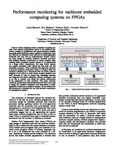
SingleCore F1
DualCore F1
Performance
Power
Performance
Power
Performance
Power
Figure 1 compares the performance-to-power ratios for a single core, a dual core, and a single core with doubled frequency.
SingleCore 2 x F1
Figure 1. Performance vs. Power
3
Integration
As core and memory technologies advance and operation frequencies increase, the surrounding system logic bus limits performance due to board signaling issues at higher speeds. Therefore, external buses are slower than their on-chip equivalents, creating bottlenecks. The difference between internal and external bus speeds, coupled with the intermediate logic delay, further exposes bandwidth deficiencies and latencies of devices operating at higher frequencies. It is a mistake to integrate a high-performance core on a device that does not incorporate enough peripherals and interfaces to make full use of the core’s computing power. Pulling the majority of the system logic on chip also reduces board design complexity and offers compatibility protection in the sense that the core, the caches, the peripherals, and the interfaces are truly integrated by the device’s vendor.
3.1
Widening the Memory Bottleneck
Memory subsystems have historically been the principal bottleneck in high-end processing systems. Recent developments in memory technology have yielded high transfer rates with features such as double data rate 2 (DDR2), which currently offers an effective transfer rate of 667 MHz. This compares favorably with single data rate technology, which runs at 133 MHz and was still common in designs two to three years ago. But designers are now turning to memory latency to squeeze every little bit available from today’s systems. Until now, much of the system logic, including the memory controller, has been external, in the form of north and south bridges. Off-chip buses typically have to run at a lower frequency and, as a result, the latency between the microprocessor and memory controller suffers. Pulling the controller on chip improves latency by a factor of 3 to 4, because the bus speed is proportional to the bandwidth and inversely proportional to the latency.
Multi-Core Microprocessors in Embedded Applications Rev. 0 4
Freescale Semiconductor
Integration
Another way to improve performance is to provide two memory controllers, one for each core. Instead of doubling the frequency, which would require memory that operates at a speed not yet commercially available, the path is widened at the original frequency, following the principle of parallelism as demonstrated by the second instantiation of the core. Interleaving the physical memory across two controllers could radically reduce the latency for some shared-memory SMP applications by allowing twice the number of open pages allowed by a single controller. Likewise, in a non-SMP system each core can benefit by having its own truly independent memory, eliminating memory dependencies between cores on a single device. The result is the doubling of bandwidth in a dual-core system.
3.2
Optimizing On- and Off-Chip Caches
Undeniably, on-chip memory can be expensive in terms of die area and cost. Smart designs can be employed to minimize AC power consumption, but cache does contribute to static power. On the positive side though, doubling the L2 cache to 1 MB, for example, can boost performance by 30% to 100%, depending on the application. Even a 30% increase for a device change that requires almost no engineering changes is often worthwhile. Of course, the benefit depends on how often the instruction code fits in L2 cache during a particular application. Performance increases can be even higher if the L2 runs at the core clock rate. The increased static power is on the order of 1 W, which most designs can afford, considering the advantages. Given the costs, additional levels of off-chip memory are hard to justify, especially when one considers that an off-chip cache such as an L3 must be 8 to 16 times larger than the L2 to significantly increase performance. More often than not, the expense of off-chip memory, in terms of die area for the tags, increased pinout packaging, cost, and power, outweighs any performance gain.
3.3
Core Network
Of course, memory is not the only bandwidth performance constraint in today’s high-end processors. It is also important to consider how to move data in and out of the device, and fast. Consider the communications market, in which high-end applications typically require high-speed interfaces, such as Gigabit Ethernet, for the data or backplane, and SRIO (Serial RapidIO) for the backplane. Backplane interconnects range from the widely available, cheaper, Gigabit Ethernet technology, to the higher bandwidth SRIO for high-end embedded applications. The successful deployment of SRIO illustrates the influence that the embedded market now has to warrant the development of such a switched backplane technology, designed specifically for embedded systems. Until now embedded systems have relied on cheaper commodity desktop-aimed connectivity standards such as PCI which makes the arrival of an SRIO a significant milestone in embedded systems. It offers features such as memory-mapped and frame-based/cell-based I/O transactions, including SAR (segmentation and reassembly), that are ideal for embedded systems and embedded communications systems in particular. The advantage of integrating such interfaces on dual-core devices is the ability to closely link the processing between the interfaces and the cores. This can allow a flexible and efficient overlap of data processing that is simply not available in discrete processors with surrounding system logic. Considering a Gigabit Ethernet interface as an example, the interface hardware block can effectively perform some early parsing and classification at wire speed for free, and can therefore offload the core substantially by creating a processing pipeline between the interface and the core. It is also important to ensure that the memory subsystem can cope with multiple high-speed interfaces that make heavy demands on bandwidth to and from memory.
Multi-Core Microprocessors in Embedded Applications Rev. 0 Freescale Semiconductor
5
Operating Systems and System Partitioning
3.4
Simplifying Cache Coherency
There are other advantages to integrating dual cores onto a single device. Multi-processor (MP) systems are by no means new, but until now discrete cores shared memory using memory/cache coherency schemes that relied on cores snooping one another’s memory/cache accesses over an external bus. If the snooping core detected an access to a memory block for which it had an updated version in its cache, it would have to write the updated block to main shared memory before the requesting core could retrieve a valid version. So as well as increasing the memory bandwidth and latency, the integration of dual cores allows inter-core buses 3 to 4 times faster than external buses, making snooping far less of a strain on the inter-core buses than a discrete processor solution would be.
3.5
Real World Implications
Note that just for 1-Gbps full-duplex bridging between a Gigabit Ethernet and SRIO, a minimum of 500 MB/s is tied up just for handling DMAs between the interfaces and memory. That is, 125 MB/s from Gigabit Ethernet to RAM, 125 MB/s from RAM to SRIO, 125 MB/s from SRIO to RAM, and 125 MB/s from RAM to Gigabit Ethernet. At least 2 GB/s of valuable memory bandwidth is tied up just to move four Gigabit Ethernet interfaces’ worth of traffic in and out of memory.
4
Operating Systems and System Partitioning
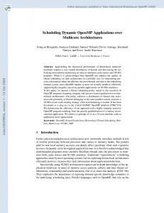
Obviously, SMP applications are a key use for dual-core devices. Figure 2 shows ease of transition from two discrete devices supporting SMP and their system logic to one single integrated device.
CPU Core
CPU Core
System Logic
Figure 2. Migration to Dual Core
A common misconception is the notion that dual-core devices are limited to SMP applications. As mentioned earlier, the inclusion of extra peripherals, such as an additional memory controller, increases flexibility. With intelligent design, microprocessor designers are adding necessary hooks and functionality to permit not just non-SMP support with identical OS on each core, but also a different OS on each core. Multi-Core Microprocessors in Embedded Applications Rev. 0 6
Freescale Semiconductor
Dual Core Strikes the Balance
A good example is a data plane application in which each core deals with one direction. This requires some low-level hardware translations since both cores’ operating systems must believe that they are resident at physical memory address zero, even though this is technically only possible for one core. This seemingly small design consideration gives an edge in terms of flexibility. In fact, it is not uncommon to have two processors in a communications system, one for control plane and the other for data plane. In this case, each core’s data or control function is better suited to a particular operating system but still has to pass some information to the other core. This is driving operating-system vendors to cooperate with each other and define standardized messaging methods to enable this cooperative asymmetric multi-processing between homogenous and heterogeneous operating systems in dual-core devices. Of course, this cooperation is also required for sharing peripherals at boot and run time within the dual-core device.
5
Dual Core Strikes the Balance
Historically, scaling processor frequencies has given the required performance without too much concern about power consumption, although it has always been desirable for microprocessor designers to strike a balance between power and performance. However, now this balance is imperative, especially in power-sensitive embedded applications, and even more so recently with exacerbated 90-nm leakage effects. The balance can be achieved by opting for parallelism using dual cores rather than an even higher-performing discrete core. Smart design is, of course, a third factor to balance in this scenario. Integrating memory controllers on chip vastly reduces latencies and increases bandwidths, historically two of the largest bottlenecks in MP systems and in microprocessors in general. The inter-processor bus speed was also a bottleneck in SMP systems, exhausted by snooping and other shared processor activities. Dual-core devices can easily offer a threefold increase in inter-processor bus frequency. Smart design also captures present and future system requirements in terms of flexible multi-OS and complex software configurations. Integrated dual-core devices offer the ideal balance and are therefore a promising solution for low-power embedded applications.
Multi-Core Microprocessors in Embedded Applications Rev. 0 Freescale Semiconductor
7
How to Reach Us: Home Page: www.freescale.com email:
[email protected] USA/Europe or Locations Not Listed: Freescale Semiconductor Technical Information Center, CH370 1300 N. Alma School Road Chandler, Arizona 85224 (800) 521-6274 480-768-2130
[email protected] Europe, Middle East, and Africa: Freescale Halbleiter Deutschland GmbH Technical Information Center Schatzbogen 7 81829 Muenchen, Germany +44 1296 380 456 (English) +46 8 52200080 (English) +49 89 92103 559 (German) +33 1 69 35 48 48 (French)
[email protected] Japan: Freescale Semiconductor Japan Ltd. Technical Information Center 3-20-1, Minami-Azabu, Minato-ku Tokyo 106-0047 Japan 0120 191014 +81 3 3440 3569
[email protected] Asia/Pacific: Freescale Semiconductor Hong Kong Ltd. Technical Information Center 2 Dai King Street Tai Po Industrial Estate, Tai Po, N.T., Hong Kong +800 2666 8080
[email protected] For Literature Requests Only: Freescale Semiconductor Literature Distribution Center P.O. Box 5405 Denver, Colorado 80217 (800) 441-2447 303-675-2140 Fax: 303-675-2150 LDCForFreescaleSemiconductor@ hibbertgroup.com
multicoreWP Rev. 0 01/2005
Information in this document is provided solely to enable system and software implementers to use Freescale Semiconductor products. There are no express or implied copyright licenses granted hereunder to design or fabricate any integrated circuits or integrated circuits based on the information in this document. Freescale Semiconductor reserves the right to make changes without further notice to any products herein. Freescale Semiconductor makes no warranty, representation or guarantee regarding the suitability of its products for any particular purpose, nor does Freescale Semiconductor assume any liability arising out of the application or use of any product or circuit, and specifically disclaims any and all liability, including without limitation consequential or incidental damages. “Typical” parameters which may be provided in Freescale Semiconductor data sheets and/or specifications can and do vary in different applications and actual performance may vary over time. All operating parameters, including “Typicals” must be validated for each customer application by customer’s technical experts. Freescale Semiconductor does not convey any license under its patent rights nor the rights of others. Freescale Semiconductor products are not designed, intended, or authorized for use as components in systems intended for surgical implant into the body, or other applications intended to support or sustain life, or for any other application in which the failure of the Freescale Semiconductor product could create a situation where personal injury or death may occur. Should Buyer purchase or use Freescale Semiconductor products for any such unintended or unauthorized application, Buyer shall indemnify and hold Freescale Semiconductor and its officers, employees, subsidiaries, affiliates, and distributors harmless against all claims, costs, damages, and expenses, and reasonable attorney fees arising out of, directly or indirectly, any claim of personal injury or death associated with such unintended or unauthorized use, even if such claim alleges that Freescale Semiconductor was negligent regarding the design or manufacture of the part.
Freescale™ and the Freescale logo are trademarks of Freescale Semiconductor, Inc. All other product or service names are the property of their respective owners.
© Freescale Semiconductor, Inc. 2005.