ICWE 2008 Workshops, 7th Int. Workshop on Web-Oriented Software Technologies – IWWOST 2008
Multi-level Dialog Modeling in Highly Interactive Web Interfaces Efrem Mbaki1, Jean Vanderdonckt1, Josefina Guerrero1, Marco Winckler2 1 Université catholique de Louvain, Louvain School of Management, Belgian Lab. of Computer-Human Interaction, Place des Doyens, 1 B-1348 Louvain-la-Neuve, Belgium
[email protected] 2
IRIT, Université Toulouse 3, France, 118 route de Narbonne, F-31062 Toulouse cedex 9, France http://liihs.irit.fr/winckler/,
[email protected]
Abstract
As web user interfaces become more sophisticated both in functionalities and reactivity, the dialog of such user interfaces is highly interactive and therefore raises the need for abstracting these capabilities into an advanced dialog model that enables modeling such dialogs. To address this need, multi-level dialog modeling enables designers to model a dialog at two inter-related levels of abstraction (i.e., concrete and abstract dialog) and at five levels of granularity: object-level (dialog at the level of a particular objects such as a widget), low-level container (dialog at the last level of decomposition of user interface containers, such as a group box), intermediary-level container (dialog at any non-terminal level of decomposition such as a dialog box or a web page), within-application level (dialog at the level of an interactive application), and across applications-level (dialog across user interfaces of different interactive applications).
1. Introduction Among all models involved in Model-Driven Engineering (MDE) of User Interfaces (UIs) of any interactive application in general or for a web application in particular, the dialog model is probably one of the most challenging remaining problems due to several reasons: Lack of ontological definition [12]: different terms, e.g., dialog, navigation, behavior, dynamics, conversation, the “feel”, are inconsistently used to refer to the dynamic aspects of a UI, as opposed to the presentation, which refers to as the static aspects of a UI, e.g., its layout. In this paper, we define a dialog model as the model that captures all dynamic aspects of a UI behavior. This therefore includes dynamics at any level of any
object that may appear in a UI. This definition will lead us to define five particular levels. Lack of precise abstraction [8]: in principle, MDE suggests three levels of abstraction (i.e., computing independent model, platform-independent model, and platform-specific model). These three levels are rarely observed in the area of dialog modeling where the platform-specific level remains predominant. Lack of continuity [12]: when two levels of abstractions are covered, it is not always obvious to see how modelto-model mappings (whether it is achieved through transformations or not) are ensured to establish and maintain continuity between them. Lack of expressiveness [20]: the demand for more sophisticated dialogs stems for a dialog model that is capable enough to accommodate the description of desired dynamic aspects, such as animations, transitions, the two traditional forms of adaptation (i.e., adaptability and adaptivity). A modern dialog model should be expressive enough to model dynamic aspects. Risk for modeling complexity: it is likely that a more expressive model tend to be more complex to define and therefore to use in general.
In this paper, we attempt to address the problem of dialog modeling in a comprehensive way in order to address the aforementioned shortcomings. For this purpose, Section 2 will report on significant work related to the area of dialog modeling. Section 3 will define the semantics of a dialog model respectively at the platform-specific level (concrete UI) and at the platform-independent level (abstract UI) with a derivation from a computing-independent model (task model). Section 3 will then define five levels of granularity. Section 4 will conclude the paper by presenting some future avenues of this work.
38
ICWE 2008 Workshops, 7th Int. Workshop on Web-Oriented Software Technologies – IWWOST 2008
tangles called states. State changing mechanisms are represented with edges between states. State changing is triggered by events and can be further conditioned. Statecharts facilitate the representation of state nesting, state history, concurrency and external interrupts. Statecharts [10] propose solutions to the shortcomings of state transition diagrams: statecharts have representational capacities for modularity and abstraction. The number of states with respect to the complexity of the modeled system increases slower with statecharts than with state transition diagrams. Statecharts avoid the problem of duplicating states and transitions. States in statecharts are hierarchical and capable of representing different levels of abstraction. Statechart are more convenient for multimodal interfaces as they provide nesting facilities, external interrupt specification and concurrency representation. Statecharts have been also specialized for specifying the dialog of web interfaces through StateWebCharts, that can be edited via a SWCEditor [22]. And-Or graphs: borrowed from Artificial Intelligence, AND-OR graphs have been used to branch to various sub-dialogs depending on conditions, for instance in [3]. And-or graphs have been expanded towards function chaining graphs [3] by combining them with data flow diagrams [19]. Event-Response Languages: they treat input stream as a set of events [9]. Events are addressed to event handlers. Each handler responds to a specific type of event when activated. This type is specified in a condition clause. The body of the event generates another event, changes internal state of the system or calls an application procedure. Several formalisms are suited for eventresponse specification. They can be distinguished following their capacity in managing dialog state variables and concurrency control. Production rules and pushdown automata [16] are often used to describe eventresponse specifications. Petri Nets are a graphical formalism associated with a formal notation. Petri nets are best suited to represent concurrency aspects in software systems. Petri nets represent systems with state variables called places (depicted as ellipses), and state-changing operators called transitions (depicted as rectangles. Connections between places and transitions are called arcs (represented by edges). State marking mechanism called tokens (represented by black solid circles distributed around places). State change is the consequence of a mechanism called firing. A transition is red when all of its input places contain tokens. Firing involves the redistribution of tokens in the net i.e., input tokens are withdrawn from input places and output tokens are added in output places. Like State Charts, Petri nets hold mechanisms to represent additional conditions and nested states. Petri nets
2. Related Work Dialog models enable to reason about the UI behavior. Consequently, dialog models are often considered as a continuation of task model concepts. This explains why the task model has been extensively used to derive a dialog model, for instance, in an algorithmic way [13] or in a logical way supported by model-to-model transformations [12] and graph grammars [7,12]. We hereafter give a brief survey of dialog modeling methods that percolated into the field of Human-Computer Interaction (HCI) development methods [3, 8, 9, 16]: Backus-Naur Form (BNF) grammars: they are typically used to specify command languages [9]. Command languages express commands that modify the state of the UI on the user’s initiative. Grammars are particularly good in detecting inconsistencies within command sets. An inconsistent UI may contain unordered or unpredictable interaction. Inconsistency renders the UI error prone and hard to learn. Grammars are both efficient and effective for expressing sequential commands or users actions in general, but become complex for multimodality. State transition diagram are a finite state machine representation that consists in a graph of nodes linked by edges [21]. Each node represents a particular state of the system. Each edge species the input (i.e., event) required to go from one state to another. State transition diagrams have been subject to several extensions [21] and specializations, like Statecharts [10] that provide a mean for specifying the dynamic behavior of the interface. State transition diagrams present several drawbacks for modeling the UI. Indeed, today's UI tend to be modeless where one state can lead to many states. Furthermore this can be done using many different widgets of the UI. Theses two requirements match the quality criteria of reachability and device multiplicity. In consequence, state transition diagrams are prone to a combinatorial explosion and tend to replace nodes by screen prints. In [14], the transition space is restricted to events and transitions that are triggered by window managers in graphical state transition diagrams, thus supporting only simple windows transitions [20]. Many other forms of dedicated state transition diagrams have been extensively used for dialog modeling without identifying which one is superior to another one with respect to various criteria: dialog charts [1], dialog flows [4], interaction object graph [5], Abstract Data Views [6], dialogue nets [11]. Statecharts: similarly to state transition diagrams, they are supported by a graphical representation of dynamic aspects of systems [10]. Some work especially address the modeling of UI behavior with statecharts [18, 22]. Statecharts represent state variables with rounded rec-
39
ICWE 2008 Workshops, 7th Int. Workshop on Web-Oriented Software Technologies – IWWOST 2008
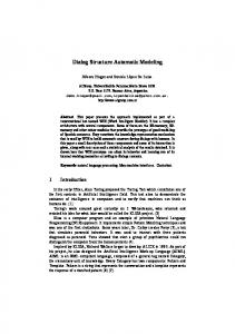
have the advantage of being entirely formal [2]. Thus, model checking of interest properties of the dialog model could be applied [17]. Fig. 1 graphically depicts some of these dialog models in families of models. Each family exhibits a certain degree of model expressiveness (i.e., the capability of the model to express advanced enough dialogs), but at the price of a certain model complexity (i.e., the easiness with which the dialog could be modeled in terms specified by the meta-model). At the leftmost part of Fig. 1 are located BNF and EBNF grammars since they are probably the least expressive dialog models ever, but they do not support many dialog aspects. They we can find respectively State Transitions Networks and their derivatives, then Event-Response Systems. Petri nets are probably the most expressive models that can be used to model dialogs, but they are also the most complex to achieve. Therefore, we believe that we could be less expressive and complex than Petri nets if Event-Condition-Action systems are considered. Model complexity
BNF, EBNF,…
in a system state change. The specification of a behavior may be decomposed into three types of elements: an event, a condition, and an action. An event is a description of a run-time occurrence that triggers an action. The general format of a ECA rule is: (ON Event, IF Condition, THEN Action). The Event specifies when the rule should be fired, the Condition specifies the logical condition when it should be fired and the Action determines what methods should be executed for this purpose. Some canonical events are described in Table 1. They consist of any system event (i.e., issued from a process belonging to the domain), user interface event (i.e., issued in the context of the user interface). For instance movePointer([X], [device]) refers to an event that consists in moving a pointer in the context of a CIO [X]. Events cannot make any reference to coordinates. The concept of context of an object (identified by its id) is used to reference a display area where a particular object is rendered. Note that, the negative expression of an object context is also allowed. For instance, depress(NOT[X]), [device]) refers to a depress event (e.g., a mouse down) outside the context of [X]. [X] is unimportant in the realization of an event in such a case a value null is referenced. The [device] parameter makes reference to the device from which the event is generated. Each device or device part, is referenced in a device model (not in the scope of this dissertation) with a unique identifier.
Petri nets ICO
STN, ESTN,…
State charts, StateWebCharts, ADV
ECA DISL Our dialog model
ERS Model expressiveness
CIO Events System event ellapsedTime(n), systemEvent(eventName) Graphical User Interface Events
Figure 1. Model complexity as a function of their expressiveness.
All CIOs
3. Semantics of Dialog Modeling In this section, we present the most salient aspects of the two levels of dialog modeling with respect to the Final User Interface (FUI). A FUI is hereby referred to as any UI running on any computing platform with any interaction modality (e.g., graphical, vocal, tactile, haptic or multimodal), whether it is rendered by markup language interpretation or by code generation.
graphical
graphicalContainer textComponent Slider Spin
movePointer(X,device), pointerOver(X,device), moveOutPointer (X, device), click (X,device), doubleClick (X, device), depress(X,device), release (X, device), dragOver(X,Y,device), dragDrop(X,Y, device), hasFocus(X), lostFocus(X). resize(xFactor,yFactor) Change move(cursor,x) spinUp, spinDown
Table 1. List of some canonical CUI events.
3.1. Concrete User Interface A Concrete User Interface (CUI) is defined as the abstraction of any Final User Interface (FUI) with respect to computing platforms, but with the interaction modality given. According to MDE, it is a platform-specific model (PSM). A CUI is made up of Concrete Interaction Objects (CIO), which are abstractions of widgets found in those platforms. Any CIO may be associated with any number of behaviors (Fig. 2). A behavior is the description of a Event-Condition-Action (ECA) mechanism that results
Events can be composed into more complex event expressions using a subset of the LOTOS operators as used in IdealXML [15]. “|||” indicates a concurrence of events (to be interpreted as a disjunction). “>>” indicates a strict sequence of events. “|=|” indicates an order independent sequence of events. “(n)” indicates a finite iteration of events where n is an integer indicating the iteration factor. For instance, click (Button1, Mouse1LeftBut) |=| depress (null, KeyBrd_Z) is an event that is an order independent
40
ICWE 2008 Workshops, 7th Int. Workshop on Web-Oriented Software Technologies – IWWOST 2008
composition of a mouse click on a button and a keyboard depress. A condition is the expression of a state that has to hold true before (pre-condition) or after (post-condition)
an action is performed. A condition may be positive or negative.
Figure 2. The semantics of the dialog model as a ECA system at the concrete user interface level. We express condition as patterns (i.e., a partial description of a state) on the user interface specification itself. Conditions may be composed using traditional logical operator. “AND”, “OR”, “XOR” indicate respectively a conjunction, a disjunction, an exclusive disjunction of conditions. “IMPLIES” indicates an implication between two conditions. An action is a process that results in a state change in the system. An action can be of three types:
3. A transition, also called navigation, is a description of a change in the container’s visibility property of a user interface system. A transition has a source (a navigation individual component) and a target (generally a container).
3.2. Abstract User Interface An Abstract User Interface (AUI) is defined as the abstraction of any CUI with respect to interaction modality. According to MDE, it is a platform-independent model (PIM). An AUI is made up of Abstract Interaction Objects (AIOs), which are abstractions of CIOs found in existing interaction modalities, and linked through abstract relationships (Fig. 3). Therefore, an AUI only specifies interaction between a user and a system in totally independent terms. Only later on, once the interaction modalities are selected and once the target computing platform is elicited, this AUI will be turned into CIOs and final widgets, respectively. Abstract Interaction Object (AIO) may be of two types Abstract Individual Components (AIC) and Abstract Containers (AC). An Abstract Individual Component (AIC) is an abstraction that allows the description of interaction objects in a way that is independent of the modality in which it will be rendered in the physical world. An AIC may be composed of multiple facets. Each facet describes a particular function an AIC may endorse in the physical world. Four main facets are identified:
1. A method call is a call to a method that is external to the UI. If a domain model exists, all method calls must reference a method belonging to this model. A method call is normally specified with the name of the method (under the form Class.methodName), but other referencing techniques are not forbidden. The method call parameters can be specified by making a reference to the value of a property of an object belonging to the CUI. 2. A transformation system is the expression of any property change at the UI level [25]. We use a mechanism to specify property changes on the UI. To avoid too much forward reference, it can be said that a transformation system can be explained as follows: when a pattern is found in CUI specification, changes should occur on the elements matching the pattern. A transformation system might be, for instance, “when a green button is found in the specification, change the color property of this button to red” or “For all text components belonging to the main window, double their font size”.
41
ICWE 2008 Workshops, 7th Int. Workshop on Web-Oriented Software Technologies – IWWOST 2008
1. 2. 3. 4.
An input facet describes the input action supported by an AIC. An output facet describes what data may be presented to the user by an AIC. A navigation facet describes the possible container transition a particular AIC may enable. A control facet describes the links between an AIC and system functions i.e., methods from the domain model when existing.
A single AIC may assume several facets at the same time. The AIO that reifies this multi-facetted AIO will assume all those ‘functionalities’. For instance, a CIO may display an output while accepting an input from a user, ensure a transition between windows and trigger a method defined in the domain model. An Abstract Container (AC) is an entity allowing a logical grouping of other abstract containers or abstract individual components. AC are said to support the execution of a set of logically/semantically connected tasks. They are called presentation units in some cases or work spaces. An AC may be reified, at the concrete level, into one or more graphical containers like windows, dialog boxes, layout boxes or time slots in the case of auditory user interfaces. Abstract User Interface Relationships (AUI relationship) are relationships that can be drawn between abstract interaction objects of all kinds. Various types of abstract relationships may be defined at this level: Decomposition relationship allows specifying a hierarchical structure of abstract containers and abstract individual components. AbstractAdjacency relationship indicates that two AIO are logically adjacent. Spatio-temporal relationship allows a specification of a very precise layout in time or space in a way that is independent of any modality. Dialog control relationship allows a specification of a flow of control between the abstract interaction objects. Like for task models, LOTOS operators are used for this purpose. For instance a relationship AIC1.EnterCountry []> AIC2.EnterPro vince indicates that AIC2 cannot be initiated while AIC1 is not achieved and that AIC1 has provided a value for the data on which the two components synchronize with. Like for tasks, an interpretation for each type of LOTOS operator may be provided in terms of pre/postconditions, termination, initiation states.
2.
3.
4.
5.
3.3. Five Levels of Dialog Granularity
a CIO or a AIO. In most cases, UI toolkits and Integrated Development Environments (IDEs) come up with their own widget set with built-in, predefined dialog. For instance, a push button comes up with its native dialog (or behavior) that can be only modified by overwriting the methods that define its behavior. Most IDEs do not allow such a superseding, only toolkits allow the developer to redefine an entirely new dialog for a particular widget, but this programming is very complex. Low-level container dialog modeling: This level models the dialog at the level of any container of other objects that is a leaf node in the decomposition. Typically, this could be a terminal AC at the AUI level or a group box at the CUI level in case of a graphical interaction modality. If the UI is vocal, then an auditory display should be implemented that marks the boundaries of this vocal group. For instance, by pronouncing the beginning and the end of the group. Intermediary-level container dialog modeling: this level models the dialog at the level of any nonterminal container of objects, that is any container that is not a leaf node in the container decomposition. For any graphical UI, this could be a window, a dialog box, or the various tabs of a tabbed dialog box. This level models the dialog at the level of top containers within a same interactive application such as a web application or a web site. It thus regulates the navigation between the various containers of a same application. Within-application dialog modeling: This level models the dialog at the level of top containers within a same interactive application such as a web application or a web site. It therefore regulates the navigation between the various containers of a same application. For instance, SketchiXML [20] allows the designer to graphically specify within-application dialog by affecting predefined ECA rules between web pages. Each such ECA rule represents a dialog pattern, such as Open-Close, Activate-deactivate. For instance, the Open-Close pattern means that when a web page is closed, the next page in the transition is opened. Across-application dialog modeling: Since the action term of a ECA rule could be either a method call or an application execution, it is possible to specify a dialog across several applications by calling an external program. Once the external program has been launched, the dialog that is internal to this program (withinapplication dialog) can take place.
4. Conclusion
Based on AUI and CUI, five levels of dialog granularity can be identified and specified: 1. Object-level dialog modeling: this level models the dialog at the level of any particular object, such as
In this paper, we have introduced a definition of a dialog model at both concrete and abstract UI levels, which
42
ICWE 2008 Workshops, 7th Int. Workshop on Web-Oriented Software Technologies – IWWOST 2008
[9] M. Green, A survey of three dialogue models. ACM Transactions on Graphics, 5(3), July 1986, pp. 244–275. [10] D. Harel, Statecharts: A visual formalism for complex systems, Science of Comp. Prog., 8, 1987, pp. 231–274. [11] C. Janssen, A. Weisbecker, and J. Ziegler, Generating user interfaces from data models and dialogue net specifications, Proc. of InterCHI’93 (Amsterdam, 24-29 April 1993), ACM Press, New York, 1993, pp. 418–423. [12] Q. Limbourg and J. Vanderdonckt, Addressing the Mapping Problem in User Interface Design with UsiXML, Proc. of TAMODIA’2004 (Prague, November 15-16, 2004), ACM Press, NY, 2004, pp. 155–163. [13] K. Luyten, T. Clerckx, K. Coninx, and J. Vanderdonckt, Derivation of a Dialog Model from a Task Model by Activity Chain Extraction, Proc. of DSV-IS’2003 (Madeira, 4-6 June 2003), Lecture Notes in Computer Science, Vol. 2844, Springer, Berlin, 2003, pp. 203–217. [14] E. Mbaki and J. Vanderdonckt, Window Transitions: A Graphical Notation for Specifying Mid-level Dialogue, Proc. of TAMODIA’2002 (Bucharest, 18-19 July 2002), Academy of Economic Studies of Bucharest, INFOREC Printing House, Bucharest, 2002, pp. 55–63. [15] F. Montero, V. López-Jaquero, J. Vanderdonckt, P. Gonzalez, M.D. Lozano, and Q. Limbourg, Solving the Mapping Problem in User Interface Design by Seamless Integration in IdealXML, Proc. of DSV-IS’2005 (Newcastle upon Tyne, 13-15 July 2005), S.W. Gilroy, M.D. Harrison (eds.), Lecture Notes in Computer Science, Vol. 3941, SpringerVerlag, Berlin, 2005, pp. 161-172. [16] D. Olsen, Pushdown automata for user interface management, ACM Transactions on Graphics, 3(3), 1984, pp. 177– 203. [17] P. Palanque and R. Bastide, Petri net based design of userdriven interfaces using interactive cooperative object formalism, Proc. of DSV-IS’94 (Bocca di Magra, June 1994), Springer Verlag, Vienna, 1994. [18] State Chart XML (SCXML): State Machine Notation for Control Abstraction. W3C Working Draft, 21 February 2007, http://www.w3.org/TR/scxml/ [19] J. Vanderdonckt, J.-Cl. Tarby, and A. Derycke, Using Data Flow Diagrams for Supporting Task Models, Supplementary Proc. of DSV-IS’98 (Abingdon, 3-5 June 1998), Eurographics Assoc., Aire-la-Ville, pp. 1–16. [20] J. Vanderdonckt, Q. Limbourg, M. Florins, Deriving the Navigational Structure of a User Interface, Proc. of Interact’2003 (Zurich, 1-5 September 2003), IOS Press, Amsterdam, 2003, pp. 455–462. [21] A. Wasserman, Extending State Transition Diagrams for the Specification of Human-Computer Interaction, IEEE Trans. on Soft. Engineering, 11(8), 1985, pp. 699–713. [22] M. Winckler and P. Palanque. StateWebCharts: A formal description technique dedicated to navigation modelling of web applications. Proc. of DSV-IS’2003 (Madeira, 4-6 June 2003), Lecture Notes in Computer Science, Vol. 2844, Springer, Berlin, 2003, pp. 61–76. [23] M. Winckler, F. Trindade, J. Vanderdonckt, Cascading Dialog Modeling with UsiXML, Proc. of DSV-IS’2008 (Kingston, July 16-18, 2008), Lecture Notes in Computer Science, Vol. 5136, Springer, Berlin, 2008, pp. 12–135.
represent respectively the PSM and PIM levels in MDE. For both, ECA rules are used to specify the dialog at five different levels of granularity. Five levels of granularity of this dialog model have been introduced. A dialog at any level of granularity can be equally modeled in the terms of an ECA system that consist of ECA rules. Depending on the UI level of abstraction (AUI or CUI), the events, the conditions, and the actions are different: the AUI events represent abstractions of CUI events, AUI actions represent abstractions of CUI actions, etc. For a mono-device dialog or for a multi-device dialog but with the same interaction modality (like in [8]), the CUI level is enough. For more interaction modalities, the AUI level should be specified with an explicit mapping between the levels using the same support as specified in [12]. In the near future, we are pursuing effort towards specifying the dialog at multiple levels, separately or simultaneously in a coordinated way. For this purpose, the cascading style sheet mechanism of XML has been applied to the corresponding UsiXML models so as to form a cascading dialog modeling [23]. In this way, it is expected that high level properties and values are progressively propagated from one level to another while preserving quality properties, such as consistency.
5. References [1] G. Ariav and L.-J. Calloway, Designing conceptual models of dialog: A case for dialog charts, SIGCHI Bulletin, 20(2), 1988, pp. 23–27. [2] R. Bastide and P. Palanque, A Visual and Formal Glue Between Application and Interaction, J. of Visual Language and Computing, 10(5), 1999, pp. 481–507. [3] F. Bodart, A.-M. Hennebert, J.-M. Leheureux, I. Provot, J. Vanderdonckt, and G. Zucchinetti, Key Activities for a Development Methodology of Interactive Applications, Chapter 7, in Benyon, D., Palanque, Ph. (Eds.), “Critical Issues in User Interface Systems Engineering”, Springer-Verlag, Berlin, 1995, pp. 109-134. [4] M. Book and V. Gruhn, Efficient Modeling of Hierarchical Dialog Flows for Multi-Channel Web Applications, Proc. of 30th COMPSAC’2006 (Chicago, 17-21 September 2006), IEEE Computer Society, Los Alamitos, 2008, pp. 161–168. [5] D.A. Carr, Specification of interface interaction objects, Proc. of ACM CHI’94 (Boston, 24-28 April 1994), ACM Press, New York, 1994, pp. 372–378. [6] D. Cowan and C. Pereira de Lucena, C., Abstract Data Views: An Interface Specification Concept to Enhance Design for Reuse, IEEE Transactions on Software Engineering, 21(3), 1995, pp. 229-243. [7] M. Goedicke and B.E. Sucrow, Towards a formal specification method for graphical user interfaces using modularized graph grammars, Proc. of IWSSD’96 (Washington, DC, 1996), IEEE, Los Alamitos, 1996. [8] J. Gomez, C. Cachero, O. Pastor, Conceptual Modeling of Device-Independent Web Applications, IEEE Multimedia, 8(2), 2001, pp. 26-39.
43