multi-level optimization approach for creating digital shapers. Creating input shapers in the digital domain leads to linear constraint equations, so the difficulties.
Proceedings of the American Control Conference Arlington, VA June 25-27, 2001
Multi-Level Optimization Techniques for Designing Digital Input Shapers Michael J. Robertson William E. Singhose Department of Mechanical Engineering Georgia Institute of Technology Atlanta, G A 30332
Abstract Input shaping decreases residual vibration in flexible systems by filtering the reference command with a sequence of impulses known as the input shaper. Input shaping techniques have been proven highly successful on a large class of computer-controlled systems. While some shapers may be determined in closed form, often a nonlinear optimization is needed to create the desired shaper. This paper proposes a multi-level optimization approach for creating digital shapers. Creating input shapers in the digital domain leads to linear constraint equations, so the difficulties of nonlinear optimization are avoided. Furthermore, the multiple levels of optimization allow for both primary and secondary design constraints to be optimized.
1. Introduction An extensive array of control schemes have been developed to control unwanted vibration in flexible systems [l, 4, 14, 22, 241. One approach involves designing a reference command that leads to low levels of vibration [2, 5, 6, 10-121. One of the more recent and successful approaches is to generate a reference command that drives the system to cancel out its own vibration. The earliest incarnation of command generation was developed in the 1950’s by O.J.M.Smith [20]. His posicast control method involved breaking a step of certain magnitude into two smaller magnitude steps, one of which is delayed onehalf period of vibration. Unfortunately, his technique was extremely sensitive to modeling errors [21]. It wasn’t until 1990 that Singer and Seering developed reference commands that were robust enough to be effective on a wide range of systems[ 151. The robust input shaping method is implemented by convolving a sequence of impulses, known as the input shaper, with a desired system command to produce a shaped input that is then used to drive the system. This process is demonstrated in Figure 1. The amplitudes and time locations of the impulses are determined by solving a set of constraint equations that attempt to limit the unwanted dynamic response of the system. The constraint equations can consist of
O-7803-6495-3/01/$10.00 0 2001 AACC
269
’
-
Time
J
0
Time
O
A
O
A
Figure 1: Input Shaping. 1) residual vibration constraints, 2) robustness constraints, 3) impulse constraints and 4) timeoptimality. In addition, a wide variety of performance specifications can be added to the set of constraints [9, 13, 161. The elimination of the unwanted vibration comes at the expense of the system’s rise time. The rise time is delayed by the shaper’s duration, A. Therefore, it is always desirable to create shapers with the shortest duration possible. The constraint on residual vibration amplitude can be expressed as the ratio of residual vibration amplitude with shaping to that without shaping. The percentage vibration can be determined by using the expression for residual vibration of a second-order harmonic oscillator of frequency w and damping ratio 5,which is given in [3]. The vibration from a series of impulses is divided by the vibration from a single impulse to get the percentage vibration: V(W,
6 )= e-@. J [C(WC)I2 + [S(w,C)I2
Y
(1)
where,
and
(3) If V(w,
15
Figure 5: Sensitivity Plot for ZV Shapers.
0
0.1
0.2
0.3
0.4
0.5
0.6
0.7
0.2
0.3
0.4
0.5
0.6
0.7
0.4132
0
0.1
Figure 4: (a) Continuous, (b) DigitizedContinuous and (c) Minimum-Duration Digital ZV Shapers. locations are fixed constants, so the exponential, sine, and cosine terms are now known constants. The equation reduces to a set of unknown impulse amplitudes multiplied by a set of known constants. The goal is to find the set of impulse amplitudes that meet the requirements. In the following sections, the multistage process is demonstrated by creating digital ZV and SI shapers.
3. Digital Input Shapers 3.1 Digital Zero Vibration (ZV) Input Shapers Although there are more robust shapers than the ZV, it is very useful for demonstration purposes. The design constraints are the following: 1) the minimum duration shaper must produce zero vibration at the modeling frequency, 2) the impulses must sum to unity, and 3) the amplitudes of the impulses must be positive. Impulses that sum to unity have unity shaper gain and insure that the shaped commands have the same final setpoint as the unshaped command. Pqsitive impulses are used to limit the excitation of unmodeled high frequency modes [17].
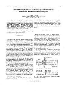
The digital ZV shaper was designed for a lightly damped (c=0.05), 1 Hz system. The digital time step was set to 0.1 second. The continuous, digitizedcontinuous and minimum duration digital shapers for this system are shown in Figures 4a, 4b and 4c, respectively. To create the digitized-continuous shaper, the second impulse of the continuous ZV shaper was distributed to the two closest allowable impulse locations. It is of interest to note that there is a significant difference between the digitized-continuous and digital ZV shaper. This difference results from the two different methods used to create the shapers. The constraint equations for the digitized shaper are different from those used to create the continuous, and consequently the digitized-continuous ZV shapers. Figure 5 shows the sensitivity curves of the shapers shown in Figure 4. While all the shapers meet the zero vibration constraint when the model is perfect, the increase in vibration as the frequency changes is not as steep for the digital shaper as for the continuous shaper or the digitized-continuous shaper. Therefore, the digital shaper is slightly more robust to modeling errors than the digitized-continuous shaper, which, in turn, is more robust than the continuous shaper. The first level optimization minimizes the shaper duration while satisfying the vibration and robustness constraints. Secondary constraints can be used to tailor a digital shaper to a specific application. One possible secondary constraint is to minimize perceived lag between the original input to the system and the shaped input. Another secondary constraint could be to limit the excitation of unmodeled higher frequency modes. This section will concentrate on two different auxiliary ZV shaper constraints: maximum robustness and minimum rise time.
3.2 Maximum Robustness
27 1
]-Step
2 r
' E
0.4 1
0.2
-
Response
1
r--l --- -- - -....&
Minimum Duration Maximum Robustness
.
o ' b .
0
-
2-
6.5
' i
1.5
2
2.5
3
Time (sec)
Figure 7: 2ndOrder Response to Digital Shapers.
Figure 6: Shaped Commands. One of the major tradeoffs in using input shaping is the rise time versus robustness decision. In general, to add robustness, or insensitivity to modeling errors one must increase the rise time, or shaper duration. Figure 5 shows the digital ZV shaper is more robust than the digitized-continuous shaper, even though the shapers have the same duration. In this section, the secondary constraint used in the multistage algorithm is to maximize the robustness. This is done by minimizing the-vibration response at points other than the modeling frequency, namely, at 99% and 101% of the modeling frequency. Minimizing these points flattens out the sensitivity curve to ensure that the insensitivity is as large as possible. The sensitivity plot for the Maximum-Robustness ZV shaper is also shown in Figure 5 . The Maximum Robustness ZV shaper is slightly more robust than the Minimum Duration (1" stage optimization) shaper. Thus, the Minimum duration (1" stage optimization) result takes adv,antage of the shaper duratiodinsensitivity trade-off. While the increased robustness is small in this case, it can be more pronounces on 'the more robust shapers. ~
3.3 Minimum Rise Time One of the side effects of implementing input shaping on systems is the distortion to the original unshaped commands. The distortion comes largely in the form of a delay (longer rise time). This phenomenon can be seen in Figure 1. One method to reduce this effect is to maximize the amplitude of the first.impulse in the shaper. As shown in Grosser [8], getting close (-90%) to the setpoint quickly, but taking longer to complete the task reduces the perception of the lag in the shaped response. Grosser's method used a longer overall duration to minimize the perception of lag. Maximizing the first impulse as a secondary constraint also reduces the perception of a delay in the response of the system.
Frequency Ratio ( w ~ ~ , ~ ~ , I u - J
Figure 8: Sensitivity Plots for Digitized Shapers. An example case is shown in Figure 6. The unshaped input is a unity magnitude step command. The shaped commands for the Minimum Duration (1'' stage optimization), Maximum Robustness and Minimum Rise Time are shown. The Minimum Rise Time command starts at a higher value than the other shaped commands, and the last step is much smaller than the other shaped commands. In this case, it appears as if the Minimum Rise Time command reaches the setpoint quicker than the other shaped commands. To demonstrate the advantage if the Minimum Rise Time shaper, the response of a 2"dorder system was simulated. Figure 7 compares the unshaped step response to the responses using the Maximum Robustness and -the Minimum Rise Time Shapers. Note that the Minimum Rist Time Shaper causes the system to approach the set point much faster. The appearance of a faster response does not come without a price. A sensitivity plot (Figure 8) shows that maximizing the first impulse causes a reduction in the robustness of the shaper. In fact, the Minimum Rise Time shaper's insensitivity almost coincides with that of the Digitized-Continuous Shaper, the least robust of the digital shapers.
3.4 Digital Specified Insensitivity Input Shapers
272
.
the amplitude of that impulse is distributed to two closest allowable impulse locations.
[=I:[ Frequency Ratio ( O , ~ , ~ ~ O , , &
3
[=I:[
Figure 9: Sensitivity Curve for SI Shaper In this section, the multistage optimization routine is used to create digital Specified Insensitivity (SI) shapers. SI shapers are used when the robustness requirements are formulated as a system constraint. This type of shaper is extremely useful when only a nominal value of the system's parameters is known or can be estimated. Digital SI shapers were designed for the same 1 Hz, 0.05 damping ratio, system as in the previous section. The 5% Insensitivity was set to 0.4. That is, the vibration response must be less than 5% over the range 0.8 to 1.2 times the modeling frequency. The primary constraint equations for the digital SI shaper are as follows: 1) impulse amplitudes must be nonnegative, 2) impulses must sum to unity and 3) the vibration percentage must be below the toleration limit (5%) for the specified range of frequencies. The sensitivity curves for the continuous, digitized-continuousand Minimum-Duration (lststage optimization) shaper results are shown in Figure 9. The continuous and digitized-continuous shapers keep the vibration percentage below the toleration limit for the entire range of frequencies to be suppressed. However, the response of the Minimum Duration (1" stage optimization) result exceeds the toleration limit at a frequency ratio slightly greater than 1. Frequency sampling is used to formulate the constraint equations, so there may be places were the vibration exceeds the toleration limit slightly. This problem is not of any practical importance. The impulse amplitudes and time locations for the continuous SI, digitizedcontinuous SI and the Minimum-Duration SI shapers are given in equation 4,5, and 6, respectively. A close inspection of Figure 9 leads to an interesting observation. Unlike the case of the ZV shapers, there is almost no difference between the continuous and digitized-continuous SI shaper sensitivity curves. There is a difference, however, between the Minimum-Duration (1" stage optimization result) and the other SI shapers. The impulse amplitudes and time locations are shown below. This representation is an excellent example of how the digitized version of the continuous shaper is created. When an impulse in the continuous shaper falls in a region between allowable digital locations,
[=I:[
0.3042 0
0.4680
0.2278
1
(4)
0.4923 0.9821
0.3042 0.0360 0.4320 0.0408 0.1870 0 0.4 0.5 0.9 1.0 0.2926
0
0.0018 0.1269 0.2149 0.1516 0.2122 0.3
0.4
0.5
0.6
1.0
3.5 Secondary Constraints Another way that the digitized-continuous SI and the Minimum Duration (1'' stage optimization) SI differ is in the number of nonzero impulses in the command. A secondary constraint of minimizing the number of impulses in the shaper can be formulated in order to reduce the number of small amplitude impulses in the shaper. Figure 8 shows the vibration response for all the SI shapers. Due to the nature of the constraint equations, there is no difference in the response of the Minimum Duration (1" stage optimization) and the Minimum Rise Time SI shaper. However, the number of nonzero impulses has been reduced to four. The Minimum-Impulse Shaper is given by the following
[=I:
0.4320 0.4391 0.0266 0.1933 0 0.5 0.6 1.0
The results when the SI commands are convolved with a step of unity magnitude are shown in Figure 10. Similar to the result of the Digital ZV shaper, maximizing the Minimum Rise Time SI starts the command with a larger amplitude than any other SI shaper. It also has the added effect of reducing the number of impulses in the shaper, which reduces the distortion of the original command.
4. Conclusions Creating input shapers in the digital domain allows for the use of linear optimization techniques, but creates shapers that are slightly longer than the continuous versions. A multistage algorithm was developed to optimize a secondary constraint such as robustness, rise time, or number of impulses. The multistage algorithm was demonstrated by creating digital ZV and SI shapers with optimized secondary constraints.
273
I
-l ---Minimum
1 -
0.8
-l 3 . YI
0.6
Duration SI
-
[ 141 M. Papdopoulos and E. Garcia, "Closed-Loop Pole Design for Vibration Suppression," Journal of Guidance, Control and Dynamics, 3, 1997, pp. 333-337. [I51 N.C. Singer and W.P. Seering, "Preshaping Command Inputs to Reduce System Vibration," J. of Dynamic Sys., Measurement, and Control, March, 1990, pp. 76-82. [I61 W. Singhose, A. Banerjee, and W. Seering, "Slewing Flexible Spacecraft with Deflection-Limiting Input Shaping," AIAA J. of Guidance, Control. and Dynamics, 2, 1997, pp. 291-298. [I71 W. Singhose, N. Singer, and W. Seering, "TimeOptimal Negative Input Shapers," J. of Dynamic Systems, Measurement, and Control, June, 1997, pp. 198-205. [18] W. Singhose, T. Singh, and W. Seering, "On-Off : Control with Specified Fuel Usage," J. Dynamic Systems, Measurement, and Control, 2, 1999, pp. 206- 212. [I91 W.E. Singhose, W.P. Seering, and-N.C. Singer, "Input Shaping for Vibration Reduction with Specified Insensitivity to Modeling Errors,'' Japan-USA Sym. on Flexible Automation. Boston, MA, 1996. [20] O.J.M. Smith, "Posicast Control of Damped Oscillatory Systems," Proceedings of the IRE, September, 1957, pp. 1249-1255. . [21] G.H. Tallman and O.J.M. Smith, "Analog Study of Dead-Beat Posicast Control," IRE Transactions on Automatic Control, March, 1958, pp. 14-21. [22] M. Tomizuka, "Zero Phase Error Tracking Algorithm for Digital Control," ASME Journal of Dynamic Systems, Measurement, and Control, March, 1987, pp. 65-68. [23] T.D. Tuttle and W.P. Seering, "AZero-placement Technique for Designing Shaped Inputs to Suppress Multiple-mode Vibration," American Control Con$ Baltimore, MD, 1994, pp. 2533-2537. [24] J.L. Wiedemch and B. Roth, "Dynamic Synthesis of Cams Using Finite Trigonometric Series," ASME Journal of Engineeringfor Industry, February, 1975, pp. 287-293.
:
0.4
1
0.2
-
o-0.2
I
0
0.2
0.4
0.6
0.8
I
1.2
r1.4
Time (sec)
Figure 10: Convolved SI Inputs.
Bibliography [I] H. Asada, 2.-D. Ma, and H. Tokumaru, "Inverse Dynamics of Flexible Robot Arms: Modeling and Computation for Trajectory Control," J. of Dynamic Systems, Measurement, and Control, 2, 1990, pp. 177-185. [2] S.P. Bhat and D.K. Miu, "Precise Point-to-Point Positioning Control of Flexible Structures," J. of Dynamic Sys., Meas., and Control, 4, 1990, pp. 667-674. [3] R.E. Bolz and G.L. Tuve, CRC Handbook of Tables for Applied Engineering Science. Boca Raton, FL: CRC Press, Inc., 1973, pp. 1071. [4] R.H. Cannon and E. Schmitz, "Initial Experiments on the End-Point Control of a Flexible One Link Robot," Int. J. of Robotics Research, No. 3, 1984. [5] R.L. Farrenkopf, "Optimal Open-Loop maneuver Profiles for Flexible Spacecraft," J. of Gui&nce and Control, 6, 1979, pp. 491-498. [6] J. Feddema, et al., "A Comparison of Maneuver Optimization and Input Shaping Filters for Robotically Controlled Slosh-Free Motion of an Open Container of Liquid," American Control Conf: Albuquerque, NM, 1997. [7] K. Grosser, J. Fortgang, and W. Singhose, "Limiting High Mode Vibration and Rise Time in Flexible Telerobotic Arms," Con$ on Systemics, Cybernetics, and Informatics. Orlando, FL, 2000. [8] K. Grosser and W. Singhose, "Command Generation for Reducing Perceived Lag in Flexible Telerobotic Arms," JSME International Journal, 4,2000. [9] S . Lim and J. How, "Input Command Shaping Techniques for Robust, High-Performance Control of Flexible Structures," AIAA Guidance, Navigation, and Control Conf: San Diego, CA, 1996. [IO] Q. Liu and B. Wie, "Robust Time-Optimal Control of Uncertain Flexible Spacecraft," J. of Guidance, Control, and Dynamics, 3, 1992, pp. 597-604. [ l l ] P.H. Meckl, P.B. Arestides, and M.C. Woods, "Optimized S-Curve Motion Profiles for Minimum Residual Vibration," American Control Conference. Philadelphia, PA, 1998. [ 121 B.R. Murphy and I. Watanabe, "Digital Shaping Filters for Reducing Machine Vibration," IEEE Transactions on Robotics and Automation, April, 1992, pp. 285-289. [ 131 L.Y. Pao, "Multi-Input Shaping Design for Vibration Reduction," Automatica, 1, 1999, pp. 81-89.
274