To wire a modular jack with CAT-5/5E wiring, follow the wire color code for the
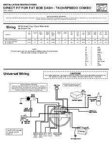
TIA/EIA-568-A wiring ..... Note: The satellite dish and receiver, CCTV Camera,.
SQUARE D Multi-Link Structured Wiring System Class 1400
Schneider Electric Brands
Table of Contents Introduction . . . . . . . . . . . . . . . . . . . . . . . . . . . . . . . . . . . . . . . . . . . . . . . . . . . . . . . 5 Product Description . . . . . . . . . . . . . . . . . . . . . . . . . . . . . . . . . . . . . . . . . . . . . . . . . . . . 5 Application Data . . . . . . . . . . . . . . . . . . . . . . . . . . . . . . . . . . . . . . . . . . . . . . . . . . . . . . . 5
Wiring Guide . . . . . . . . . . . . . . . . . . . . . . . . . . . . . . . . . . . . . . . . . . . . . . . . . . . . . . 7 Recommended Pre-wire Schemes . . . . . . . . . . . . . . . . . . . . . . . . . . . . . . . . . . . . . . . . . 7 Installing and Terminating the Cable . . . . . . . . . . . . . . . . . . . . . . . . . . . . . . . . . . . . . . . 8 Recommended Product Configurations . . . . . . . . . . . . . . . . . . . . . . . . . . . . . . . . . . . . 11
Enclosures and Brackets . . . . . . . . . . . . . . . . . . . . . . . . . . . . . . . . . . . . . . . . . . . 19 Product Description . . . . . . . . . . . . . . . . . . . . . . . . . . . . . . . . . . . . . . . . . . . . . . . . . . . 19 General Information and Application Data . . . . . . . . . . . . . . . . . . . . . . . . . . . . . . . . . . 22
Television/Telephone Combination Hubs . . . . . . . . . . . . . . . . . . . . . . . . . . . . . . . 25 Product Description . . . . . . . . . . . . . . . . . . . . . . . . . . . . . . . . . . . . . . . . . . . . . . . . . . . 25 General Information and Application Data . . . . . . . . . . . . . . . . . . . . . . . . . . . . . . . . . . 25 Specifications . . . . . . . . . . . . . . . . . . . . . . . . . . . . . . . . . . . . . . . . . . . . . . . . . . . . . . . . 26
Voice and Data Network Hubs . . . . . . . . . . . . . . . . . . . . . . . . . . . . . . . . . . . . . . . 27 Product Description . . . . . . . . . . . . . . . . . . . . . . . . . . . . . . . . . . . . . . . . . . . . . . . . . . . 27 Specifications . . . . . . . . . . . . . . . . . . . . . . . . . . . . . . . . . . . . . . . . . . . . . . . . . . . . . . . . 30 Expanding the Network . . . . . . . . . . . . . . . . . . . . . . . . . . . . . . . . . . . . . . . . . . . . . . . . 30
Audio Distribution Hub . . . . . . . . . . . . . . . . . . . . . . . . . . . . . . . . . . . . . . . . . . . . . 31 Product Description . . . . . . . . . . . . . . . . . . . . . . . . . . . . . . . . . . . . . . . . . . . . . . . . . . . 31
Video Distribution Hubs . . . . . . . . . . . . . . . . . . . . . . . . . . . . . . . . . . . . . . . . . . . . 33 Product Description . . . . . . . . . . . . . . . . . . . . . . . . . . . . . . . . . . . . . . . . . . . . . . . . . . . 33 General Information and Application Data . . . . . . . . . . . . . . . . . . . . . . . . . . . . . . . . . . 38 Specifications . . . . . . . . . . . . . . . . . . . . . . . . . . . . . . . . . . . . . . . . . . . . . . . . . . . . . . . . 38
Satellite Multi-Switch . . . . . . . . . . . . . . . . . . . . . . . . . . . . . . . . . . . . . . . . . . . . . . 41 Product Description . . . . . . . . . . . . . . . . . . . . . . . . . . . . . . . . . . . . . . . . . . . . . . . . . . . 41 General Information and Application Data . . . . . . . . . . . . . . . . . . . . . . . . . . . . . . . . . . 41
Modulators . . . . . . . . . . . . . . . . . . . . . . . . . . . . . . . . . . . . . . . . . . . . . . . . . . . . . . 45 Product Description . . . . . . . . . . . . . . . . . . . . . . . . . . . . . . . . . . . . . . . . . . . . . . . . . . . 45 General Information and Application Data . . . . . . . . . . . . . . . . . . . . . . . . . . . . . . . . . . 49 Technical Information . . . . . . . . . . . . . . . . . . . . . . . . . . . . . . . . . . . . . . . . . . . . . . . . . . 50 Specifications . . . . . . . . . . . . . . . . . . . . . . . . . . . . . . . . . . . . . . . . . . . . . . . . . . . . . . . . 52
Video Cameras . . . . . . . . . . . . . . . . . . . . . . . . . . . . . . . . . . . . . . . . . . . . . . . . . . . 55 Product Description . . . . . . . . . . . . . . . . . . . . . . . . . . . . . . . . . . . . . . . . . . . . . . . . . . . 55 General Information and Application Data . . . . . . . . . . . . . . . . . . . . . . . . . . . . . . . . . . 56 Technical Information . . . . . . . . . . . . . . . . . . . . . . . . . . . . . . . . . . . . . . . . . . . . . . . . . . 59 Specifications . . . . . . . . . . . . . . . . . . . . . . . . . . . . . . . . . . . . . . . . . . . . . . . . . . . . . . . . 59 3 04/03
© 2001–2003 Schneider Electric All Rights Reserved
Table of Contents Video Wall Plate . . . . . . . . . . . . . . . . . . . . . . . . . . . . . . . . . . . . . . . . . . . . . . . . . . 61 Product Description . . . . . . . . . . . . . . . . . . . . . . . . . . . . . . . . . . . . . . . . . . . . . . . . . . . 61 General Information and Application Data . . . . . . . . . . . . . . . . . . . . . . . . . . . . . . . . . . 61
IR Target and Emitter . . . . . . . . . . . . . . . . . . . . . . . . . . . . . . . . . . . . . . . . . . . . . . 63 Product Description . . . . . . . . . . . . . . . . . . . . . . . . . . . . . . . . . . . . . . . . . . . . . . . . . . . 63 General Information and Application Data . . . . . . . . . . . . . . . . . . . . . . . . . . . . . . . . . . 63
Accessories . . . . . . . . . . . . . . . . . . . . . . . . . . . . . . . . . . . . . . . . . . . . . . . . . . . . . 65 Product Description . . . . . . . . . . . . . . . . . . . . . . . . . . . . . . . . . . . . . . . . . . . . . . . . . . . 65
Troubleshooting . . . . . . . . . . . . . . . . . . . . . . . . . . . . . . . . . . . . . . . . . . . . . . . . . . 69 General Troubleshooting Techniques . . . . . . . . . . . . . . . . . . . . . . . . . . . . . . . . . . . . . 69 Radio Frequency Troubleshooting Techniques . . . . . . . . . . . . . . . . . . . . . . . . . . . . . . 69 Modulator Troubleshooting for Cameras . . . . . . . . . . . . . . . . . . . . . . . . . . . . . . . . . . . 70
Glossary . . . . . . . . . . . . . . . . . . . . . . . . . . . . . . . . . . . . . . . . . . . . . . . . . . . . . . . . 71 Structured Wiring Terms . . . . . . . . . . . . . . . . . . . . . . . . . . . . . . . . . . . . . . . . . . . . . . . 71
Index . . . . . . . . . . . . . . . . . . . . . . . . . . . . . . . . . . . . . . . . . . . . . . . . . . . . . . . . . . . 75 Model Number Index . . . . . . . . . . . . . . . . . . . . . . . . . . . . . . . . . . . . . . . . . . . . . . 79
4 © 2001–2003 Schneider Electric All Rights Reserved
04/03
Introduction Product Description PRODUCT DESCRIPTION
INTRODUCTION
The Square D Multi-Link Structured Wiring System represents the next generation of products for home networks. The Square D Multi-Link Structured Wiring System offers a complete range of products that integrate voice, data, and video applications for a complete system solution. Square D warrants the product to be free from defects in materials and workmanship for eighteen months from the date of invoice from Square D or its authorized sales channel. The devices are UL® Listed for use in US markets and CUL® Listed for use in Canada.
APPLICATION DATA The structured wiring modules are wired using Category 5 (CAT-5) or Category 5E (CAT-5E) cable and RG-6 coaxial cables. All structured wiring modules are easily installed into enclosures, also supplied by Square D. Category 5 and 5E Cable Category 5 and 5E cables are made up of four unshielded twisted pairs. Each pair is color coded for application identification. CAT-5 or CAT-5E cables are recommended for telecommunications, camera, and data applications. CAT-5 and CAT-5E cables will support standard analog telephone, digital telephone, and data. Category 5 and Category 5E cables meet TIA/EIA–586A and 570 standards for data applications such as high-speed Internet access. The cables have a bandwidth of 100 MHz and data transmission speeds up to 100 Mbps. CAT-5 and CAT-5E cable installations provide connections for immediate and future computer, video, and telephone upgrades, thus protecting the long-term resale value of the home. NOTE: Category 5/5E cables should not be routed parallel to the AC power wiring unless 14 in. (356 mm) of separation or greater is provided. Cross Category 5/5E cables over AC power wires at 90°. Aluminum Foil Shielding
Foam Polyethylene Dielectric Core
RG-6 Coaxial Cable F-Connector
Copper Clad Center Conductor PVC Jacket
60% Aluminum Braid
RG-6 Quad
RG-6 coaxial cable has an 18 gauge copper coated steel center conductor, polyethylene dielectric core, aluminum braid, and PVC jacket. Standard “F” connectors are used for video, audio, and television equipment connections. Under extreme noise conditions, such as near a radio or television transmitter, use quad-shielded RG-6 cable. NOTES: RG-6 coaxial cable should not be routed parallel to AC power wiring unless 14 in. (356 mm) of separation or greater is provided. Cross RG-6 coaxial cable over AC power wires at 90°. When bending coaxial cable, a radius of no less than four times the outside diameter of the cable should be maintained. For RG-6 coaxial cable, the bending radius should be 1 - 1 1/2 inches or greater.
04/03
© 2001–2003 Schneider Electric All Rights Reserved
5
Section 1–Introduction
www.squared.com/multilink
Section 1–Introduction
Introduction
www.squared.com/multilink
Application Data Installing Modules into Enclosure All structured wiring modules are easily installed into enclosures, also supplied by Square D. Using the hook on the back of the module, hang the module on the enclosure grid, swing the module into place, and push the button on the right side of the module to lock the module into the enclosure grid.
Hook Enclosure grid
Push button to lock module into place
6
Telephone Service Hub Square D model SDM412PJ Telephones RJ-31X R 4 T R 3 T R 2 T R 1 T Expansion
© 2001–2003 Schneider Electric All Rights Reserved
04/03
www.squared.com/multilink
Wiring Guide Recommended Pre-wire Schemes
WIRING GUIDE
Structured wiring cables run from the wall boxes in the various rooms of the house directly to the structured wiring enclosure (called home run wiring). Two types of wire are used for communication and entertainment: CAT-5 or CAT-5E, made up of 4-UTP (unshielded twisted pairs), and RG-6 coaxial. CAT-5 or CAT-5E 4-UTP wires handle voice and data for up to four telephone lines. CAT-5 or CAT-5E wires can have two to four unshielded twisted pairs. Square D recommends four pairs. RG-6 coaxial wires handle television (antenna or cable), satellite dish, cable modem, or AV modulator signals. Refer to the following table for the recommended wiring schemes. These wires run from the enclosure to the locations indicated in the table. Recommended Pre-wire Schemes Typical Room
Media Center Wire Type
Good
Phone/TV
CAT–5
1
RG–6
1
Wire Type Better
Best
Phone/TV/ Ethernet
Phone/TV/ Ethernet/ Satellite Receiver
Quantity
Quantity
CAT–5
2
RG–6
1
Wire Type
Quantity
CAT–5
2
RG–6
2
Phone/Satellite Receiver/AV Modulators
Phone/TV/Ethernet/ Satellite Receiver/AC Modulators Phone/TV/Ethernet/ Satellite Receiver/AC Modulators/Hi–speed Data
Home Office Wire Type
Quantity
CAT–5
1
RG–6
3
Wire Type
Quantity
CAT–5
2
RG–6
3
Wire Type
Quantity
CAT–5
3
RG–6
3
Wire Type Phone/TV/Cable Modem
Quantity
CAT–5
1
RG–6 Phone/TV/ Ethernet/Cable Modem Phone/TV/ Ethernet/Satellite Receiver/Cable Modem/Hi–speed Data
Wire Type
2 Quantity
CAT–5
2
RG–6 Wire Type
2 Quantity
CAT–5
3
RG–6
3
Telephone and Video Camera Pre-wire Scheme Recommended Color Coding for Category 5/5E Wire Category 5/5E Wire Color
Usage
Gray
Telephone
Red
Security
Blue
Data
Yellow
Demarc and Gateway
For pre-wiring telephone modules, use one gray CAT-5/5E cable from each telephone and modem location, web television and/or satellite box location, and telephone demarcation point (the interface from the telephone service provider). For pre-wiring video camera modules, use one red CAT-5/5E cable from each video camera location (for example, front door) and security panel location. Audio/Video and Television Pre-wire Scheme Recommended Color Coding for Coaxial Wire RG-6 Coaxial Wire Color
Usage
White
Use as send, upstream, or internal cable from modulators to distribution panel
Black
Use as receive, downstream, or external cable from distribution panel to televisions
For pre-wiring audio/video and television modules, use RG-6 coaxial cable. Use black coaxial cable for each television and computer location. Use white coaxial cable for each location where one or more video sources are located, the CATV demarcation point (the interface from the television service provider), and off-air antennas. For satellite dish locations, use two white coaxial cables to the distribution panel. For each satellite receiver location, use one white coaxial cable to the distribution panel. If HDTV satellite dishes are installed, four coaxial cables may be required because the satellite systems can accommodate up to four different receivers from a single dish.
04/03
© 2001–2003 Schneider Electric All Rights Reserved
7
Section 2–Wiring Guide
RECOMMENDED PRE-WIRE SCHEMES
Wiring Guide
www.squared.com/multilink
Installing and Terminating the Cable Section 2–Wiring Guide
Data Pre-wire Scheme For pre-wiring data modules, use one blue CAT-5/5E cable from each computer location, room with a separate peripheral (such as a laser printer), and room where access to the network is needed. Wiring a Telephone Wall Plate To wire a telephone wall plate, refer to the following table. NOTE: The wiring method shown in the table below requires the use of two-line telephones.
Telephone Wall Plate Wiring Using Two Six-Position, Four-Conductor Jacks (RJ-14) Cable Color
Pin Number
Connector Color (As Marked on RJ-14 Modular Connector)
White/Orange
Pin 2
White/Orange
Blue
Pin 3
Blue
White/Blue
Pin 4
White/Blue
Orange
Pin 5
Orange
Jack 1: Pairs 1 and 2
Jack 2: Pairs 3 and 4 White/Brown
Pin 2
White/Orange
Green
Pin 3
Blue
White/Green
Pin 4
White/Blue
Brown
Pin 5
Orange
When a fax machine is present or single-line telephones are used, wire line 1 (blue, blue/white pair) to the center pins (marked blue, blue/white) on the RJ-14 jack. For access to a second line for a fax machine or to enable single-line telephone use, wire line 2 (orange, orange/white pair) to the center pins (marked blue, blue/white) on a second RJ-14 jack.
INSTALLING AND TERMINATING THE CABLE 110 Punch-Down Connectors The 110 punch-down connector is an insulation displacement connection system typically included on combination telephone/video hubs, telephone hubs, and data hubs. The CAT-5/5E wires are inserted into the connectors. To push wire into the connector, use only a 110 punch-down tool. When wiring the connector, keep the wire cable sheath close to the connector and do not untwist the wire more than 1/2 in. (13 mm).
110 punch-down tool
CAT-5/5E cable
8
© 2001–2003 Schneider Electric All Rights Reserved
04/03
www.squared.com/multilink
Wiring Guide Installing and Terminating the Cable
Modular connectors are attached to each end of a CAT-5/5E jumper cable. Modular connectors are used with television, telephone, data, and Ethernet hubs. There are three six-position connector types, depending on the number and usage of lines. Eight-position connectors are used with the telephone expansion hub (model SDM48PX). For residential purposes, it is recommended that the eight-position connectors (RJ-45) are wired to the T568-A wiring standard. Refer to the table below for the modular connector type and the figures below for wiring configurations. Modular Connector Types Line Usage
Connector Type
Six-position Connectors Single-line telephones, answering machines, and modems (six-position, two-conductor)
RJ-11
Dual-line telephones and answering machines (six-position, four-conductor)
RJ-14
Three-line key service unit (six-position, six-conductor)
RJ-25
Eight-position Connectors Telephones, Ethernet (10 Base-T and 100 Base-T), and data lines (eight-position, eight-conductor)
04/03
© 2001–2003 Schneider Electric All Rights Reserved
RJ-45
9
Section 2–Wiring Guide
Modular Connectors
Wiring Guide
www.squared.com/multilink
Installing and Terminating the Cable Section 2–Wiring Guide
Wiring a Modular Connector The illustrations below show the modular connectors positioned with the tabs down, pins up, and the openings facing toward you. Pair 3
Pair 3 Pair 2 Pair 4
Pair 1
Pair 2
Pair 2
Pair 1
Pair 1
RT
T RT R
1 2 3 4 5 6
1 2 3 4 5 6
RJ-11 Connector
RJ-14 Connector
Pair 1
T T R T RR
T R T R T RT R
RJ-25 Connector
RJ-45 Connector (T568-A standard)
1 2 3 4 5 6
1 2345678
Wiring a Modular Jack To wire a modular jack with CAT-5/5E wiring, follow the wire color code for the TIA/EIA-568-A wiring standard as illustrated for the RJ-45 modular connector. Position the first pair of wires to the terminals closest to the end of the jack. Do not untwist the pairs more than 1/2 in. (13 mm) from the termination point. Push the wires into the terminals of the jack using a 110 punch-down tool and trim. After all pairs are connected, snap on strain relief caps.
110 punch-down tool
10
Strain relief caps
© 2001–2003 Schneider Electric All Rights Reserved
04/03
www.squared.com/multilink
Wiring Guide Recommended Product Configurations Section 2–Wiring Guide
RECOMMENDED PRODUCT CONFIGURATIONS The following product configurations are guides for installing a structured wiring system for the most common applications. Basic Home • Distributes two telephone lines to six locations and one cable input to four locations • Handles multiple telephone lines for voice, fax and Internet access
Catalog Number
Description
SDM18BW
18 In. (457.2 mm) Enclosure
SDM18CW
18 In. (457.2 mm) Cover
SDM26P14V
Combination Telephone/Video Hub
Incoming RG-6 coaxial cable from cable company or local antenna
RG-6 coaxial cables connected to four television wall plates
OUT
IN
OUT
IN
IN
OUT
OUT
IN
OUT
IN
532-230 5MHzto 1000MHz SPLITTER
SDM26P14V
From Telco
COMBINER
R
Telephones
R 2 T R 1 T
Combo Hub (2 lines x 6 phones, 1inpu t x 4 televisions) Square D model SDM26P14V
Incoming telephone service (two lines)
Internal telephone cables connected to six telephone wall plates (CAT–5/5E unshielded twisted pairs). Each cable can have two to four pairs of wire.
CAT-5/5E cable
04/03
© 2001–2003 Schneider Electric All Rights Reserved
11
Wiring Guide
www.squared.com/multilink
Recommended Product Configurations Section 2–Wiring Guide
Basic Home Office • Distributes four telephone lines to six locations and one cable input to four locations • Allows sharing of files and peripherals among two computers • Handles multiple telephone lines for voice, fax, and Internet access
Catalog Number
Description
SDM18BW
18 In. (457.2 mm) Enclosure
SDM18CW
18 In. (457.2 mm) Cover
SDM8D
Eight-Port Data Hub
SDM46P14V
Combination Telephone/Video Hub
Incoming RG-6 coaxial cable from cable company or local antenna
RG-6 coaxial cables connected to four television wall plates
OUT
IN
OUT
IN
IN
OUT
OUT
IN
OUT
IN
532-230 5MHzto 1000MHz
COMBINER
From Telco
SDM46P14V
R
Telephones
4 R T R 3 R T R R 2 T T R R 1 TT
Combo Hub (2 lines x 6 phones, 1 inpu t x 4 televisions) Square D model SDM46P14V
Internal telephone cables connected to six telephone wall plates (CAT-5/5E unshielded twisted pairs). Each cable can have two to four pairs of wire.
Incoming telephone service (four lines) CAT-5/5E cable
Data Hub ( 8 cables, TIA-568A)
Category 5 Compliant Square D model SDM8D
SDM8D
CAT-5/5E cable
Cables connecting to data jacks in eight wall plates
Up to eight data jacks can be wired using this equipment. However, unless an Ethernet hub is used, only two computers can be networked by connecting two RJ-45 jacks with a patch cord on the data hub. NOTE: To allow two computers to be networked, one crossover patch cord must be used somewhere in the system, i.e., between one computer and data outlet.
12
© 2001–2003 Schneider Electric All Rights Reserved
04/03
www.squared.com/multilink
Wiring Guide
If high-speed Internet service will be brought to the home over the telephone lines (DSL), the incoming telephone line should be connected to the combination hub (model SDM46P14V) and then jumped to the data hub (model SDM8D) as shown in the figure below. In this scenario, one computer can have DSL service. The high-speed Internet line can easily be moved to another computer by changing the location of the jumper on the SDM8D. Incoming RG-6 coaxial cable from cable company or local antenna
RG-6 coaxial cables connected to four television wall plates
OUT
IN
OUT
IN
IN
OUT
IN
OUT
OUT
IN
532-230 5MHzto 1000MHz SPLITTER
From Telco
SDM46P14V
R
COMBINER
Telephones
4 R T R 3 R T R R 2 T T R R 1 T
Combo Hub (2 lines x 6 phones, 1inpu t x 4 televisions)
Square D model SDM46P14V
Internal telephone cables connected to five telephone wall plates (CAT-5/5E unshielded twisted pairs). Each cable can have two to four pairs of wire.
Incoming telephone service (four lines) Sends DSL to office
Data Hub ( 8 cables, TIA-568A)
Category 5 Compliant Square D model SDM8D
DSL Modem
SDM8D
Cables connecting to data jacks in six wall plates To data jack in home office
04/03
© 2001–2003 Schneider Electric All Rights Reserved
13
Section 2–Wiring Guide
Recommended Product Configurations
Wiring Guide
www.squared.com/multilink
Recommended Product Configurations Section 2–Wiring Guide
Advanced Home Office • Distributes four telephone lines to six locations • Creates a LAN by connecting up to five computers or peripherals through the Ethernet hub (model SDM5DE) • Allows a high-speed Internet connection to be shared among computers • Distributes CATV or antenna signals to up to eight televisions Catalog Number
Description
SDM18BW
18 In. (457.2 mm) Enclosure
SDM18CW
18 In. (457.2 mm) Cover
SDM4AC
Four-Outlet AC Accessory (Two Plugs)
SDM46P
Phone Board
SDM8D
Eight-Port Data Hub
SDM5DE
Ethernet Hub
SDM38VBIR or SDM38VHIR
Video Hub
Five rooms have ethernet connections
Data Hub ( 8 cables, TIA-568A)
Category
5 Compliant
Square D model SDM8D
SDM8D
Power supply-included (model SDM350087) CAT-5/5E patch cords (models to SDM4AC SDM1DC or SDM2DC)
CAT-5 cable To data jacks in remote wall plates
Ethernet
Hub 10 BASE-T (5 RJ-45 inputs, 1 uplink) Square D model SDM5DE
1
2
3
4
Col.
5
Pwr
Link/Act.
SDM5DE Up link
5
4
3
2
1
+5VDC
LED glows when power is applied
Antenna or cable (model SDM38VHIR) Cable only (model SDM38VBIR)
IR
Gnd
+12vdc
Power supply-included (model SDM350086) to SDM4AC Adapter (included)
B +Pwr
Modulators
Televisions
SDM38VBIR
A
Up to eight televisions
RG-6 coaxial cable
14
© 2001–2003 Schneider Electric All Rights Reserved
04/03
www.squared.com/multilink
Wiring Guide
NOTES: If high-speed Internet service is brought to the home over the telephone lines (DSL), the incoming telephone line should be connected to the SDM46P and then jumped to the SDM8D through the DSL modem (as shown in the figure below). If the Internet service provider (ISP) allows multiple IP addresses to be leased to one modem, then the high-speed Internet service may be available to all the computers in the home using the Multi-Link Ethernet Hub. In this situation, the high-speed Internet line will jump from the SDM8D to the “uplink” port in the SDM5DE. All the computers connected to the Ethernet hub must have firewall software or hardware installed since they all will have access to the high-speed line at the same time. If the ISP does not allow multiple IP addresses to be leased to one modem, then replace the Multi-Link Ethernet Hub in the figure below with a router (purchased separately).
Security system connection (RJ-31X only)
Telephone Master Hub (4 lines x 6 phones) Square D model SDM46P
From Telco
Expansion Ports
Telephones
RJ31X
R T R T R 2 T R 1 T 4
SDM46P
3
Out
Four lines from telephone company (CAT-5/5E, four unshielded twisted pairs)
Five rooms have ethernet connections
Data Hub ( 8 cables, TIA-568A)
Category 5 Compliant Square D model SDM8D
SDM8D
DSL Modem Power supply-included (model SDM350087) to SDM4AC
CAT-5 cable To data jacks in remote wall plates Ethernet
1
2
3
4
Hub 10 BASE-T (5 RJ-45 inputs, 1 uplink) Square D model SDM5DE
Col.
5
Pwr
Link/Act.
SDM5DE
Up link
5
4
3
2
1
+5VDC
04/03
© 2001–2003 Schneider Electric All Rights Reserved
15
Section 2–Wiring Guide
Recommended Product Configurations
Wiring Guide
www.squared.com/multilink
Recommended Product Configurations Section 2–Wiring Guide
Advanced Video and Security Camera • Distributes four telephone lines to six locations • Creates a local channel for viewing a camera signal • Distributes camera signal along with the cable television or antenna signals to up to eight televisions • No power is necessary at the camera, it is powered through the channel injector • Multiple cameras can be added to the system (a channel injector is needed for each one) Catalog Number
Description
SDM18BW
18 In. (457.2 mm) Enclosure
SDM18CW
18 In. (457.2 mm) Cover
SDM4AC
Four-Outlet AC Accessory (Two Plugs)
SDM46P
Phone Board
SDM38VBIR
Video Hub
SDM1VC
Black and White Camera
SDM11VMB or SDM11VMH
Channel Injector
Power supply-included (model SDM350079) to model SDM4AC
SDM11VMB or SDM11VMH
Make all cables and CAT-5 connections first. Power the channel injector last. Connect antenna or incoming cable to channel injector (model SDM11VMH) CATV/Ant input or the CATV to model SDM11VMB. RG-6 coaxial cable
CAT-5/5E cable
Video camera-rear view (model SDM1VC)
SDM1VC
Power supply-included (model SDM350086) to SDM4AC
SDM38VBIR
LED glows when power is applied
IR
Gnd
+12vdc
Adapter (included)
B +Pwr
Modulators
Televisions
A
Up to eight televisions
RG-6 coaxial cable
16
© 2001–2003 Schneider Electric All Rights Reserved
04/03
www.squared.com/multilink
Wiring Guide Recommended Product Configurations
• • • • • • • •
• • •
Distributes four telephone lines to six locations Creates a local channel for viewing a camera signal Distributes camera signal along with the cable television or antenna signals to up to eight televisions No power is necessary at the camera, it is powered through the channel injector Multiple cameras can be added to the system (channel injectors can be cascaded) Video sources, such as DVD players, are connected via line level inputs to the set top modulator (model SDM41VTST) Set top modulator modulates all the inputs and combines them onto a single coaxial cable for distribution back to the video hub Output of the set top modulator is connected to port B of the video hub, which allows the video hub to be powered via the set top modulator NOTE: Port A on the video hub is also used to connect modulated signals, however, no IR control can be passed through this port Cable or antenna signal is connected to the model SDM11VMB IR targets are connected in-line with each television where IR control is desired IR emitters are connected to the set top modulator and position over the IR sensor on the video source device
Catalog Number
Description
SDM18BW
18 In. (457.2 mm) Enclosure
SDM18CW
18 In. (457.2 mm) Cover
SDM4AC
Four-Outlet AC Accessory (Two Plugs)
SDM46P
Phone Board
SDM38VBIR or SDM38VHIR
Video Hub
SDM41VTST
4-Input Set Top Modulator
SDM2VCC
Color Camera
SDM11VMB or SDM11VMH
Channel Injector
SDM1VIR
IR Target
SDM2VIR
IR Emitter
For satellite applications, see pages 41–43.
04/03
© 2001–2003 Schneider Electric All Rights Reserved
17
Section 2–Wiring Guide
Media Center and Security Camera
Wiring Guide
www.squared.com/multilink
Section 2–Wiring Guide
Recommended Product Configurations Note: The satellite dish and receiver, CCTV Camera, VCR, and DVD shown are not Square D Multi-Link products.
Satellite dish and receiver Video/audio outputs
CCTV Camera at front door Terminating jumpers (on side of unit) A BC D
Power connection
OUTPUT
RCA "Y" adapter to local monitor or Dolby Pro-Logic system
A BC D
CH B
CH D
SDM41VT
Remove jumper for Hi-Z (See manual)
CH A
CH C
POWER 15VDC 900mA
VIDEO
AUDIOL
AUDIOR
VIDEO
AUDIOL
AUDIOR
Optional IR emitter (model SDM2VIR) repeats what the IR target “sees” in the other room. Attach the IR emitter directly over the IR sensor.
Video/audio outputs Use only shielded 75 ohm coaxial cable VCR
12:00 VCR
DVD RG-6 coaxial preferred
Power option-Do not power. Power is obtained through port B of set top modulator. To more televisions Optional IR target (model SDM1VIR) may be used at any or all televison locations.
SDM38VHIR or SDM38VBIR
Control the DVD, DSS, or VCR from any room. RG-6 coaxial cable
Power supply-included (model SDM350079) to model SDM4AC
SDM11VMB or SDM11VMH
CAT-5/5E cable
Make all cables and CAT-5 connections first. Power the channel injector last. Connect antenna or incoming cable to channel injector (model SDM11VMH) CATV/Ant input or the CATV to model SDM11VMB. Security system connection (RJ-31X only) Video camera-rear view Telephone Master Hub (4 lines x 6 phones) Square D model SDM46P
From Telco
R T R T R 2 T R 1 T 4
Expansion Ports
Telephones
RJ31X
3
SDM1VC
Out
Four lines from telephone company (CAT-5/5E, four unshielded twisted pairs) SDM46P
18
© 2001–2003 Schneider Electric All Rights Reserved
Internal telephone cable connected to six telephone wall plates (CAT-5/5E unshielded twisted pairs). Each cable can have two to four pairs of wire.
04/03
www.squared.com/multilink
Enclosures and Brackets Product Description
ENCLOSURES AND BRACKETS
The enclosures are the housing components of the Square D Multi-Link Structured Wiring System. Each enclosure has a mounting grid, allowing any structured wiring module to easily mount into the enclosure. Modules can be mounted on either side of the grid and upside down. The universal mounting bracket (model SDM10BW) can be surface mounted over a single- or double-gang box or mud ring. Any Square D Multi-Link Structured Wiring module can be installed onto the mounting bracket. To give the bracket a finished look, a snap-on cover (model SDM10CW) is available. Universal Mounting Bracket (Model SDM10BW) Features: • 10 in. (254 mm) high, 6.5 in. (165 mm) wide, .35 in. (9 mm) deep • 10 in. (254 mm) of grid mounting space • Vertical or horizontal mounting • Surface mount over single- or double-gang openings • Optional cover (model SDM10CW) • Painted steel, white
SDM10BW
SDM10BW With Modules Installed
Cover (Model SDM10CW) Features: • 11 in. (279 mm) high, 6.7 in. (170 mm) wide, 4.5 in. (114 mm) deep • Snap-on cover design • Painted steel, white
04/03
© 2001–2003 Schneider Electric All Rights Reserved
19
Section 3–Enclosures and Brackets
PRODUCT DESCRIPTION
Enclosures and Brackets
www.squared.com/multilink
Product Description Enclosures (Models SDM18BW and SDM36BW)
Section 3–Enclosures and Brackets
Features: • Model SDM18BW is 18 in. (457.2 mm) high, 14.25 in. (362 mm) wide, and 3.5 in. (89 mm) deep, with 34 in. (864 mm) of grid mounting space • Model SDM18BW has two columns of grid mounting space, each column is 17 in. (432 mm) • Model SDM36BW is 36 in. (914.4 mm) high, 14.25 in. (362 mm) wide, and 3.5 in. (89 mm) deep, with 70 in. (1778 mm) of grid mounting space • Model SDM36BW has two columns of grid mounting space, each column is 35 in. (889 mm) • Side mounting tabs included for field installation • Fits between studs on 16 in. (406 mm) center lines • Surface or flush mounting • Optional combination flush/surface cover: cover dimensions for SDM18CW –19.5 in. (495.3 mm) high, 15.75 in. (400 mm) wide and SDM36CW–37.5 in. high (953 mm), 15.75 (400 mm) wide SDM18BW With Modules Installed
• Can be mounted upside down • Accepts model SDM4AC or model SDM8AC power accessory • Four 2 in. (51 mm) and two 1/2 in. (13 mm) knockouts in each endwall • Painted steel, white • Paint shield included
SDM18CW and SDM18BW
20
© 2001–2003 Schneider Electric All Rights Reserved
04/03
www.squared.com/multilink
Enclosures and Brackets Product Description
The AC power accessories (models SDM8AC and SDM4AC) mount inside the enclosures to provide a UL® listed location for power supplies. All of the enclosures accept the AC power accessories.
Features: • SDM8AC will mount four receptacles, providing eight outlets for four power supplies • SDM4AC will mount two receptacles, providing four outlets for two power supplies • Uses standard duplex receptacles, not included SDM8AC
• Mounts in any of the four corners of model SDM18BW or model SDM36BW enclosure • Mounting hardware included • UL Listed • SDM8AC covers 5.5 in. (140 mm) of grid mounting space on each side, 11 in. (280 mm) total • SDM4AC covers 5.5 in. (140 mm) of grid mounting space on one side
SDM4AC
SDM18BW with SDM4AC and Other Modules Installed
04/03
© 2001–2003 Schneider Electric All Rights Reserved
21
Section 3–Enclosures and Brackets
AC Power Accessories (Models SDM8AC and SDM4AC)
Enclosures and Brackets
www.squared.com/multilink
General Information and Application Data GENERAL INFORMATION AND APPLICATION DATA Section 3–Enclosures and Brackets
Mounting the Enclosure The enclosures can be flush mounted between studs. For versatile flush mounting, the mounting tabs are field installed. Three available positions for the flush mounting tabs allow for wall thicknesses of 1/2 in. (13 mm), 5/8 in. (16 mm) or 3/4 in. (19 mm). Nail holes are provided in each sidewall for flush mounting in existing installations. Mounting holes are also provided in the rear of the enclosure for surface mounting. Covers SDM18CW and SDM36CW are combination covers for flush or surface applications. NOTE: The enclosure should not be mounted next to an AC power distribution panel. Maintain 17.5 in. (445 mm) or more between the structured wiring panel and the home’s AC panel.
16.0
0 in (406 . on cen ter mm)
Mounting tab hole and hole inside enclosure
Knockout
Enclosure
Mounting the AC Power Accessory The AC power accessory is easily mounted into the enclosure using the hardware provided. The AC power accessory can be mounted into any corner of the enclosure. Low voltage wires exit the AC power accessory through the grommets provided. The grommets can be cut to accommodate the wiring.
Left or right
Location of knockouts for 120 VAC
OEM AC ADAPTOR Part no.: 123-456 U
Top or bottom
L
Enclosure Grommet cut for wiring
AC Power Accessory Mounting Locations (SDM8AC depicted)
22
© 2001–2003 Schneider Electric All Rights Reserved
04/03
www.squared.com/multilink
Enclosures and Brackets General Information and Application Data
The AC power accessories include a grounding lug. The enclosures do not include a separate grounding lug. However, there is a #10–32 threaded hole provided in the top and bottom endwall for the user to install ground lugs, as necessary. Installing the Cables Install the data and video cables into the enclosure through removable knockouts. Line the knockout holes with grommets (provided) to protect incoming cable. Cabling running through knockout hole Knockout hole with grommet
Grommet
Cabling in enclosure
Paint shield
Installing the Cover Cover installation is streamlined with temporary hardware (provided).
Enclosure mounting holes
Install nails through the mounting holes to temporarily align screw holes.
Cover
04/03
© 2001–2003 Schneider Electric All Rights Reserved
23
Section 3–Enclosures and Brackets
Grounding Lug
Enclosures and Brackets
www.squared.com/multilink
Section 3–Enclosures and Brackets
General Information and Application Data
24
© 2001–2003 Schneider Electric All Rights Reserved
04/03
www.squared.com/multilink
Television/Telephone Combination Hubs Product Description
PRODUCT DESCRIPTION The combination hubs provide a four-way passive splitter to distribute incoming video (CATV or antenna) signals to four locations. The hubs incorporate 110 punch-down blocks for distributing telephone lines. Combination Hubs (Models SDM26P14V and SDM46P14V) Features: • Distributes CATV or antenna to four locations • Telephone service for two lines (model SDM26P14V) or four lines (SDM46P14V) with outputs to six locations • 3 in. (76.2 mm) of grid mounting space.Video F-connectors extend 1/2 in. (13 mm) above the hub mounting pan. Allow approximately 2 in. (51 mm) clearance for cable bending radius above the module.
SDM46P14V
SDM26P14V
GENERAL INFORMATION AND APPLICATION DATA Combination Hubs See the following figure for the typical installation of combination hubs.
RG-6 coaxial cables connected to four television wall plates RG-6 coaxial cable from cable company or antenna
OUT
IN
OUT
IN
IN
OUT
OUT
IN
OUT
IN
532-230 5MHzto 1000MHz SPLITTER
From Telco
COMBINER
R
Telephones
R T R 1 T 2
Two lines from telephone company (CAT-5/5E unshielded twisted pairs)
Combo Hub (2 lines x 6 phones, 1inpu t x 4 televisions)
Square D model SDM26P14V
SDM26P14V
04/03
© 2001–2003 Schneider Electric All Rights Reserved
Internal telephone cables connected to six telephone wall plates (CAT-5/5E, two unshielded twisted pairs). Each cable can have two to four pairs of wire.
25
Section 4–Television/Telephone Combination Hubs
TELEVISION/ TELEPHONE COMBINATION HUBS
Television/Telephone Combination Hubs
www.squared.com/multilink
General Information and Application Data SPECIFICATIONS Passive Splitter Section 4–Television/Telephone Combination Hubs
The specifications for the passive video splitter portion of the combination hubs are shown in the following table.
Parameter
Insertion Loss In-Out (dB maximum)
Return Loss Input (dB maximum)
Return Loss Output (dB minimum)
Isolation OUT-OUT (dB minimum)
26
Frequency (MHz)
SDM26P14V SDM46P14V
5–40
6.7
40–400
6.9
400–500
7.2
500–600
7.5
600–1000
7.8
5–40
22
40–400
24
400–500
27
500–600
25
600–1000
23
5–40
24
40–400
26
400–500
24
500–600
25
600–1000
23
5–40
24
40–400
28
400–500
25
500–600
24
600–1000
23
Power Pass
500 mA
One port or all ports
Impedance
5–1000
75 ohms
RFI (dB)
5–1000
130 dB
© 2001–2003 Schneider Electric All Rights Reserved
04/03
www.squared.com/multilink
Voice and Data Network Hubs Product Description PRODUCT DESCRIPTION The voice and data network hubs distribute telephone and data signals to multiple locations throughout the home. Each hub uses the standard grid mounting and will fit in any enclosure model or the universal mounting bracket. Telephone Master Hub (Model SDM46P) Section 5–Voice and Data Network Hubs
Features: • Telephone service for four lines with outputs to six separate locations • Security panel connection RJ-31X only (top jack) for seizure of line 1
SDM46P
• 110 punch-down connectors • Can be mounted upside down • Expansion jack RJ-45 (bottom jack) for telephone expansion hub (model SDM48PX) • 3 in. (76.2 mm) of grid mounting space Telephone Expansion Hub (Model SDM48PX) Features: SDM48PX
• Accessory to telephone master hub (model SDM46P) • Telephone service for four lines with outputs to eight separate locations (when used with SDM46P, 14 outlets are accommodated)
Security system connection (RJ–31X only)
Telephone Master Hub (model SDM46P)
• CAT-5/5E patch cord included to connect to SDM46P • 110 punch-down connectors
Telephone Master Hub (4 lines x 6 phones)
Square D model SDM46P From Telco
Expansion Ports
• Can be mounted upside down
Telephones
• 3 in. (76.2 mm) of grid mounting space
RJ31X
R T R 3 T R 2 T R 1 T 4
• Expansion jack allows multiple SDM48PX units to be cascaded, providing expanded telephone distribution (see graphic on the left)
Out
Four lines from telephone company (CAT–5/5E, four unshielded twisted pairs)
Telephone Interface Hub/Patch Panel (Model SDM412PJ) CAT–5 patch cord Telephone Expansion Hub (model SDM48PX) Telephone Expansion Hub (4 lines x 8 phones)
RJ-45 J10
J8 110D-4 110D -4
J7 110D-4 110D -4
J6 110D-4 110D -4
J5 110D-4 110D -4
J3 110D-4 110D -4
J4 110D-4 110D -4
J2 110D-4 110D -4
J1 110D-4
RJ-45 J9
Out Blu
Blu
Blu
Blu
Blu
Blu
Blu
Blu
• RJ-45 modular jacks • Can be mounted upside down
Telephones
In
• Telephone service for four lines with outputs to twelve separate locations • 110 punch-down connectors for incoming telephone company service
Square D model SDM48PX
Expansion Ports
Features:
R T R T R T R T
4 3
• 3 in. (76.2 mm) of grid mounting space
2 1
• Expansion jack allows connection to additional SDM412PJ for large applications • Use with SDM8D data hub and SDM5DE Ethernet hub to allow easy reassignment of phone outlets to data network outlets
CAT–5 patch cord Telephone Expansion Hub (model SDM48PX) Telephone Expansion Hub (4 lines x 8 phones)
Square D model SDM48PX
Expansion Ports RJ-45 J10
Telephones J8 110D-4 110D -4
J7 110D-4 110D -4
J6 110D-4 110D -4
J5 110D-4 110D -4
J3 110D-4 110D -4
J4 110D-4 110D -4
J2 110D-4 110D -4
J1 110D-4 110D -4
In
RJ-45 J9
Out Blu
Blu
Blu
Blu
Blu
Blu
Blu
Blu
R T R T R T R T
4 3 2 1
SDM412PJ
04/03
© 2001–2003 Schneider Electric All Rights Reserved
27
Voice and Data Network Hubs
www.squared.com/multilink
Product Description Data Termination Hub (Model SDM8D) Features: • Certified 100 Base-T performance • CAT-5/5E performance in a multi-port hub • Terminates eight CAT-5/5E lines with RJ-45 jacks • Terminates eight CAT-5/5E lines with 110 punch-down connectors • Can be mounted upside down SDM8D
• Circuits may be bridged for telephone distribution • 3 in. (76.2 mm) of grid mounting space
Telephone company line
• Suitable for Digital Subscriber Line (DSL) from telephone company • Distributes Ethernet connections • Distributes camera connections
CAT-5/5E data hub (model SDM8D) TIA-568A)
Category 5 Compliant Square D model SDM8D
Data Hub ( 8 cables, TIA-568A)
CAT-5/5E data hub (model SDM8D)
The data termination hub can be used for telephone distribution by connecting two data hubs using CAT-5/5E patch cords. In the figure to the left, one hub shows the telephone lines bridged at the hub to bring telephone distribution to the jacks. The additional hub has the cables connecting to voice or data jacks in eight wall plates.
(
Section 5–Voice and Data Network Hubs
• 110 punch-down connectors are connected to the RJ-45 jacks
Category 5 Compliant H628 Square D model SDM8D
Cables connecting to voice or data jacks in eight wall plates
Bridgeable CAT-5/5E Hub (Model SDM8DB) Features: • Certified 100 Base-T performance • Eight CAT-5/5E circuits (110 to RJ-45) • Eight additional 110 connectors to bridge for telephone distribution (see diagram below) • 4.5 in. (114.3 mm) of grid mounting space
SDM8DB
The bridgeable CAT-5/5E data hub can also be used for telephone distribution. In the following figure, three telephone outlets are wired using CAT-5/5E cables terminated to the lower section of 110 punch-down connectors. The wires can also be terminated into the RJ-45 jacks via RJ-45 plugs. To bring telephone distribution to the jacks, bridge the telephone lines by running the incoming telephone lines across the top set of 110 punch-down connectors. All CAT-5/5E circuits can be bridged for telephone distribution. The remaining terminals are available for use as data terminations. The lines from the telephone company bridged across the connectors.
Data Hub (8 cables, TIA-568A) Category 5 Compliant Square D model SDM8DB
Telephone lines
28
© 2001–2003 Schneider Electric All Rights Reserved
Data lines
04/03
www.squared.com/multilink
Voice and Data Network Hubs Product Description Ethernet Hub (Model SDM5DE)
The Ethernet hub is easier to install when used as a companion piece with the data termination hub. Features: SDM5DE
• Certified 10 Base-T performance • Five-port hub • RJ-45 connectors • Can be mounted upside down • FCC and UL approved • Uplink port provided to jumper to additional SDM5DE units
VOICE AND DATA NETWORK HUBS
• 120 Vac power supply included • 4 in. (102 mm) of grid mounting space
DSL from telephone company
DSL sent to home office computer only Ethernet connection from home office Four ethernet connections Data Hub (8 cables, TIA-568A) Category 5 Compliant
Square D model SDM8DB
Hub ( 8 cables, TIA-568A)
Camera signal connects to channel injector by way of the RJ-45 patch cord
CAT-5/5E data hub (model SDM8DB)
Camera wire (CAT-5/5E)
Cables connecting to two phone jacks (one in home office) Network hub 10 base-t Square D model SDM5DE
Cable connecting to data jacks in five wall plates
Ethernet hub (model SDM5DE)
Power Link/ normal
1
2
3
4
5
10 base-t hub
Antenna or incoming cable
Channel injector (model SDM11VMH)
Power supply (model SDM350079)
Program CAT-5 video
Output
CATV /Ant
Power
Channel Injector
NOTE: The channel injector shown in this scheme is not required for Ethernet connections.
04/03
© 2001–2003 Schneider Electric All Rights Reserved
29
Section 5–Voice and Data Network Hubs
The Ethernet hub is used to provide a five port 10 Base-T hub to interface computers and printers throughout the home. This hub creates a local area network, allowing file and peripheral (printer) sharing among multiple computers. The Ethernet hub has activity LEDs for network status and diagnosis.
Voice and Data Network Hubs
www.squared.com/multilink
Technical Information SPECIFICATIONS Ethernet Hub (Model SDM5DE) Specifications at 77 + 9 °F (25 + 5 °C) Compliance Network Interface
Section 5–Voice and Data Network Hubs
Maximum Cable Length LED Indicators Environmental
Power Supply
IEEE 802.3
10 Base-T
RJ-45 ports
5
RJ-45 uplink
1
CAT-5/5E (UTP)
328 ft (100 m)
each unit
PWR, COL
each port
LINK/ACT
operating temperature
32°F to 122°F (0°C to 50°C)
model number
SDM350087
output current
800 mA maximum
output voltage
5 Vdc ± 5% regulated
input power
105–125 Vac
EXPANDING THE NETWORK To expand the network, one of the ports on the Ethernet hub is used to connect to the uplink port on the expansion hub using a straight through RJ-45 CAT-5 cable. See the graphic below.
Ethernet
Hub 10 BASE-T (5 RJ-45 inputs, 1 uplink) Square D model SDM5DE
1
2
3
4
Col.
5
Pwr
Link/Act.
Ethernet hub (model SDM5DE) Uplink
5
4
3
2
1
+5VDC
Connect to four network devices or to the “uplink” port of additional ethernet hubs.
Ethernet
Hub 10 BASE-T (5 RJ-45 inputs, 1 uplink) Square D model SDM5DE
1
2
3
4
Col.
5
Pwr
Link/Act.
Ethernet hub expansion (model SDM5DE) Uplink
5
4
3
2
1
+5VDC
Leave this port unused
Connect to four network devices or to the “uplink” port of additional ethernet hubs.
Additional hubs can be used, as long as the path between any two network devices does not exceed four hubs and five cables. NOTE: When the uplink port of a hub is used, a network device cannot be connected to port 5. All hubs must be powered.
30
© 2001–2003 Schneider Electric All Rights Reserved
04/03
www.squared.com/multilink
Audio Distribution Hub Product Description
PRODUCT DESCRIPTION Speaker Distribution Hub (Model SDM16A) Features: • Distributes one stereo audio to six rooms • 3 in. (76.2 mm) of grid mounting space • Connects with standard speaker wire (12 gauge maximum) to supply six pairs of speakers with stereo audio from one receiver or amplifier • Outputs wired (via speaker wire) to impedance matching volume controls (not supplied by Square D) • Speaker wire terminations removable for easy wiring • Speakers not supplied by Square D
SDM16A
04/03
© 2001–2003 Schneider Electric All Rights Reserved
31
Section 6–Audio Distribution Hub
AUDIO DISTRIBUTION HUB
Audio Distribution Hub
www.squared.com/multilink
Section 6–Audio Distribution Hub
General Information and Application Data
32
© 2001–2003 Schneider Electric All Rights Reserved
04/03
www.squared.com/multilink
Video Distribution Hubs Product Description PRODUCT DESCRIPTION
SDM13VS
The splitter hubs are cable company grade passive splitters that are tilted to 10° for easy connections. Three-, four-, and eight-way balanced splitters are available. The video distribution hubs amplify and distribute antenna and/or cable signals to television locations. The high headroom amplifier and bi-directional amplifier video hubs (models SDM38VHIR and SDM38VBIR) include two modulator inputs to add locally generated channels for cameras, DVDs, or VCRs. All of the video distribution hubs are compatible with NTSC and future HDTV signals. Section 7–Video Distribution Hubs
VIDEO DISTRIBUTION HUBS
Splitter Hubs (Models SDM13VS, SDM14VS, and SDM18VS) Features: • Cable company grade passive splitter • Model SDM13VS is a three-way balanced splitter, 5–1000 MHz • Model SDM14VS is a four-way balanced splitter, 5–1000 MHz SDM14VS
• Model SDM18VS is an eight-way balanced splitter, 5–1000 MHz • Splitter tilted 10° for easy connections • -130 dB RFI rejection • 2 in. (51 mm) of grid mounting space NOTES: The splitter hubs are not DC passing.
SDM18VS
Video Amplifier Hub (Model SDM16VAB) The video amplifier hub (model SDM16VAB) distributes community antenna television (CATV) or antenna signals to six televisions. The hub has four standard outputs (up to 75 ft, 22.9 m) and two long outputs (up to 150 ft, 45.8 m). The SDM16VAB has a broadband amplifier (54–806 MHz) and a 5–42 MHz return path for pay-per-view and interactive cable. The video amplifier hub works like a zero-loss splitter. The signals that are put on the antenna/CATV input will appear on the outputs with about 1dB of gain for short outputs and about 4 dB of gain for long outputs. SDM16VAB
Features: • Distributes CATV or antenna to six televisions • Four standard “short” outputs (up to 75 ft, 22.9 m) • Two long outputs (up to 150 ft, 45.8 m) • Up to four additional hubs (model SDM16VAB) can be cascaded (from the four standard “short” outputs only) of a master hub • HDTV compatible • Bi-directional with a 5–42 MHz return path for interactive applications and pay-per-view boxes • Can be mounted upside down • LED power indicator • 120 Vac power supply included • 3 in. (25.4 mm) of grid mounting space • Termination caps are not required
04/03
© 2001–2003 Schneider Electric All Rights Reserved
33
Video Distribution Hub
www.squared.com/multilink
Product Description Adding a Camera
Section 7–Video Distribution Hubs
A camera channel can be added to the video amplifier hub (model SDM16VAB) using the channel injector (model SDM11VMH or SDM11VMB) and the camera (example: model SDM2VC). The channel injector adds the camera channel to the existing off-air channels and the video amplifier hub distributes the channel to all the outputs. See the figure below.
Camera (model SDM2VC)
Program
Channel injector (model SDM11VMH)
CAT-5 video
CATV /Ant
Output
Video Amplifier
Power
Hub (1 inpu t x 6 t elev is ions)
Square D model
Video amplifier hub (model SDM16VAB)
Power
+15VDC
Short
Long
CATV/ Ant
Televisions
Camera channel is now available on all televisions in the house.
Video Hubs (Models SDM38VHIR and SDM38VBIR) The video hubs work like a zero-loss splitter and signal combiner. The signals that are put on the antenna or cable television input will appear on the outputs with about 3dB of gain. The modulator inputs will automatically appear on the outputs at an FCC legal level. Features:
SDM38VHIR
• SDM38VHIR is a high headroom amplifier video hub used with CATV systems or antennas for off-air digital and analog television signals. The amplifier handles signal differences between high-powered analog VHF (off-air television channels 2 through 13) and low-powered digital UHF (off-air television channels 14 through 69). Use SDM38VBIR if CATV services require a return path. • SDM38VBIR is a bi-directional amplifier video hub used with CATV services using pay-per-view boxes and interactive cable and has a 5–42 return path. The bi-directional system is not for use with off-air antennas. • Bi-directional with a 5–42 MHz return path for pay-per-view boxes (SDM38VBIR only) • Distributes CATV (SDM38VBIR or SDM38VHIR) or antenna (SDM38VHIR only) to eight televisions • Maximum 150 ft (46 m) coaxial cable run from all eight outputs • HDTV compatible
SDM38VBIR
34
• Two modulator inputs to add locally generated channels (camera, VCR, or DVD)
© 2001–2003 Schneider Electric All Rights Reserved
04/03
www.squared.com/multilink
Video Distribution Hubs Product Description
• Use modulator input B for IR information passing • IR repeating system using 5-volt targets • Antenna isolation compliant with FCC Part 15 requirements (SDM38VHIR only) • 120 Vac power supply and adapter included • LED power indicator • Up to eight additional hubs (models SDM38VBIR or SDM38VHIR) can be cascaded from a master hub • Termination caps are not required Modulator Inputs The high headroom amplifier and bi-directional amplifier video hubs (models SDM38VHIR and SDM38VBIR) have modulator inputs to add locally generated channels. The new channel is selected using the programming instructions included with the modulator or the channel injector (see the “Programming” section for modulators on page 50). Any television connected to the video hub output by coaxial cables can receive the signal when tuned to the proper channel. For typical installation, see the figure below.
Power supply-included (model SDM350086) Adapter (included)
LED glows when power is applied
Antenna or cable (model SDM38VHIR) Cable only (model SDM38VBIR)
IR
Gnd
+12vdc
Video hub (model SDM38VHIR)
B +Pwr
Modulators
Televisions
A
Connect modulators Modulator to A or B inputs
Up to eight televisions
DVD, VCR, or Satellite
RG-6 coaxial cable
To increase the number of modulator inputs, a modulator combiner (model SDM81VC) is connected to a video hub modulator input port to work as an expansion hub. When the modulator combiner is used with a video hub, each of the eight locations can receive the broadband feed as well as the modulated channels.
04/03
© 2001–2003 Schneider Electric All Rights Reserved
35
Section 7–Video Distribution Hubs
• 2.5 in. (64 mm) of grid mounting space
Video Distribution Hub
www.squared.com/multilink
Product Description IR Repeating System
Section 7–Video Distribution Hubs
The high headroom amplifier and bi-directional amplifier video hubs (models SDM38VBIR and SDM38VHIR) have integrated 5-volt IR engines that pass IR information, allowing control of any video device from any location by simply adding an IR target (model SDM1VIR), an IR emitter (model SDM2VIR), and a set top modulator to the system. For example, when the remote control is pointed at the IR target located at the television, the IR pulses are repeated by the emitter, which is controlling the DVD player in another location. IR information and power from the set top modulator are passed through port B only. When the modulator is connected to port A, IR remote control passing capability is not available and the video hub must be powered. All of the television ports can have targets connected. See the following figure.
IR
Gnd
+12vdc
Video hub (model SDM38VHIR)
B +Pwr
Modulators
Televisions
A
Set top modulator
IR target (model SDM1VIR)
IR emitter (model SDM2VIR)
Typical remote control
The single channel modulator (model SDM11VM), channel injectors (models SDM11VMB/SDM11VMH), and the modulator combiner (model SDM81VC) do not pass IR information for remote control. Use only a modulator with IR control, such as a set top modulator (model SDM41VTST, SDM21VTST, SDM41VT, or SDM21VT), and connect the set top modulator to the B+pwr input port of the video hub.
36
© 2001–2003 Schneider Electric All Rights Reserved
04/03
www.squared.com/multilink
Video Distribution Hubs Product Description Television Output Expansions A video hub can be connected to up to eight more video hubs, adding up to 64 television outlets. The longest recommended coaxial cable length should not exceed 150 ft (45.8 m) (total length from master hub to expansion hub and expansion hub to the television). NOTE: IR control can also be expanded using an IR control expander (ChannelPlus model 2181). Section 7–Video Distribution Hubs
For typical installation, see the figure below.
Master SDM38VHIR/VBIR
ChannelPlus model 2181 allows the SDM38VHIR/VBIR to expand IR control also. Use one 2181 for each SDM38VHIR/VBIR expansion. Expansion SDM38VHIR/VBIR
Expansion SDM38VHIR/VBIR
Modulator Combiner Hub (Model SDM81VC) The modulator combiner hub has inputs for eight modulators for distribution through a coaxial panel. The signals from all eight inputs are consolidated into a single output. The modulator combiner hub works like a zero-loss amplifier/combiner. The modulated signals that are put on the inputs will appear on the outputs with about 1dB of gain. When the output of the modulator combiner hub is connected to one of the modulator inputs of a video hub, signals will automatically appear on the video hub outputs at a legal FCC level. Features: • Combines modulator inputs from eight locations • Combines all channels into single output SDM81VC
• Accepts modulated inputs from 400–800 MHz • Modulator input expansion hub for models SDM38VBIR and SDMVHIR • 120 Vac power supply and adapter included • LED power indicator • 2.5 in. (64 mm) of grid mounting space
04/03
© 2001–2003 Schneider Electric All Rights Reserved
37
Video Distribution Hub
www.squared.com/multilink
General Information and Application Data GENERAL INFORMATION AND APPLICATION DATA
Section 7–Video Distribution Hubs
Troubleshooting Situation
Possible Solution
No picture
Check that the television and the modulator are tuned to the same channel. For example, if the modulator is broadcasting on UHF channel 16, make sure the television is on UHF 16 rather than CATV16. UHF 16 and CATV 16 are at different frequencies.
Weak UHF channel
If the television has a separate UHF input, be sure that it is connected.
Herringbone interference on modulator channel (diagonal lines)
• Move the modulator channel to another number. A low pass filter might need to be added to remove the cable company noise. • If the filter does not work, add a DC-block to remove common mode interference.
Herringbone interference on many channels, including modulator channels (disappears when you remove the CATV/antenna feed)
Use a variable attenuator and try to find a signal level where the interference just disappears. Sometimes, the problem is one station is stronger than the rest. In this case, attenuating all of the signals with a simple attenuator may cause the desired stations to be weak (snowy). Reduce the strength of only the offending station. A common FM trap will help if the problem is a nearby FM tower. If the problem is a nearby television station, usually the station management can provide suitable filters.
Audio volume is low
If you have a mono source, connect it to both right and left inputs using an RCA ‘Y’ connector. For proper audio level, both right and left inputs must be used.
No color on modulated channels
The incorrect cable standard might be in use. Not all televisions can accommodate the 1.25MHz frequency difference between the HRC and IRC cable standards.
FCC Requirements These products comply with FCC requirements. A system using these devices will comply with FCC requirements. Use only video modulators and modulator combiners that comply with Part 15 of the FCC rules and have 25 dBmV maximum output levels. Failure to do so may void the user’s authority to operate this equipment. The high headroom amplifier video hub (model SDM38VHIR) is suitable for use with an antenna or with CATV systems. The bi-directional amplifier video hub (model SDM38VBIR) is suitable for use with CATV systems only and has a bi-directional return path. The video amplifier hub (model SDM16VAB) is suitable for use with an antenna or CATV systems and also incorporates a bi-directional return path.
SPECIFICATIONS Passive Splitter The specifications for the video passive splitter portion of the combination hubs are shown in the following table. Parameter
Insertion Loss In-Out (dB maximum)
Return Loss Input (dB maximum)
Return Loss Output (dB minimum)
Isolation OUT-OUT (dB minimum)
Power Pass
38
Frequency (MHz)
Three-Way Splitter (SDM13VS)
Four-Way Splitter (SDM14VS
Eight-Way Splitter (SDM18VS) 10.5
5–40
5.3
6.7
40–400
5.5
6.9
11
400–500
5.8
7.2
11.5 12.3
500–600
6.1
7.5
600–1000
6.5
7.8
13
5–40
22
22
16
40–400
24
24
17
400–500
28
27
18
500–600
25
25
18
600–1000
24
23
18
5–40
21
24
16
40–400
23
26
20
400–500
25
24
20
500–600
24
25
21
600–1000
22
23
18
5–40
24
28
22
40–400
28
32
24
400–500
25
30
29
500–600
24
28
22
600–1000
23
25
20
500 mA
One port or all ports
Impedance
5–1000
75 ohms
RFI (dB)
5–1000
130 dB
© 2001–2003 Schneider Electric All Rights Reserved
04/03
www.squared.com/multilink
Video Distribution Hubs General Information and Application Data
Video Amplifier Hub (Model SDM16VAB) Specifications at 77 + 9 °F (25 + 5 °C) Output Run Distance (RG-6 coaxial):
Long
Short
150 ft (46 m)
75 ft (23 m)
Gain: CATV/Ant Input to Television Output
4 dB
1 dB
Television Output to CATV/Ant Input (5–42MHz reverse channel)
-8 dB
-12 dB
Forward
54–806 MHz
Reverse
5–42 MHz
Max CATV/Antenna Input (64 channels)
20 dBmV
Power Supply (SDM350086 included)
15 Vdc @ 300 mA
Section 7–Video Distribution Hubs
Bandwidth:
High Headroom Amplifier and Bi-directional Amplifier Video Hubs Specifications at 77 + 9 °F (25 + 5 °C) SDM38VHIR
SDM38VBIR
Output Run Distance (RG-6 Coaxial)
150 ft (46 m)
150 ft (46 m)
Modulator Input Distance
75 ft (23 m)
75 ft (23 m)
Gain: CATV/Ant Input to Television Output
3 dB
3 dB
Modulator Input to Television Output
-10 dB
-10 dB
Television Output to CATV/Ant Input (5–42MHZ reverse channel)
N/A
-15 dB
>80 dB
>35 dB
Forward
5–806 MHz
54–806 MHz
Reverse
N/A
5–42 MHz
Isolation: Modulator Input to CATV/Ant Bandwidth:
Max CATV/Antenna Input (64 channels)
20 dBmV
20 dBmV
Power Supply (SDM350086 included)
15 Vdc @ 300 mA
15 Vdc @ 300 mA
Modulator Combiner Hub (Model SDM81VC) Specifications at 77 + 9 °F (25 + 5 °C)
04/03
Number of Modular Inputs
8
Gain, Modulator Input to Output
~1 dB
Bandwidth
400–860 MHz
Nominal Modulator Input Level
25 dBmV
Maximum Number of Modulated Channels
16
Power Supply (SDM350086 included)
15 Vdc @ 300 mA
© 2001–2003 Schneider Electric All Rights Reserved
39
Video Distribution Hub
www.squared.com/multilink
Section 7–Video Distribution Hubs
General Information and Application Data
40
© 2001–2003 Schneider Electric All Rights Reserved
04/03
www.squared.com/multilink
Satellite Multi-Switch Product Description PRODUCT DESCRIPTION The satellite multi-switch (model SDM24VD) is a dual low noise block (LNB) connection switch for use with DIRECTV® and Dish Network® Dish 300 satellite systems. The satellite multi-switch is not suitable for use with Dish Network® Dish 500 satellite systems. The satellite multi-switch connects up to four satellite receivers to a dual LNB dish.
SDM24VD
The multi-switch locks one LNB to receive right-hand polarized signals and the other LNB to receive left-hand polarized signals. The individual satellite receivers can select any satellite channel. The multi-switch will automatically connect the satellite receivers to the correct LNB.
SATELLITE MULTI-SWITCH
• Dual LNB connections • Outputs to four satellite receivers • Compatible with DIRECTV® and Dish Network® Dish 300 systems • 950–1450 MHz • 2.5 in. (64 mm) of grid mounting space
GENERAL INFORMATION AND APPLICATION DATA Dual LNB 18 In. Satellite Dish For the installation of the dual 18 in. satellite dish to the satellite multi-switch, run two RG-6 coaxial lines from the satellite dish to the satellite multi-switch in the enclosure. Connect up to four RG-6 lines to the outputs of the satellite multi-switch. Each RG-6 coaxial line will connect to a satellite receiver. See the following figure.
LNB-A 13V
Satellite multi-switch (model SDM24VD)
LNB-B dish 18V
satellite receivers
Four standard satellite receivers
04/03
© 2001–2003 Schneider Electric All Rights Reserved
41
Section 8–Satellite Multi-Switch
Features:
Satellite Multi-Switch
www.squared.com/multilink
General Information and Application Data HDTV Dual-Dual LNB 24 In. Satellite Dish
Section 8–Satellite Multi-Switch
For the installation of an HDTV Dual-Dual LNB 24 in. satellite dish to the satellite multi-switch, run four RG-6 coaxial lines from the dish to the multi-switch included with the dish. From the multi-switch supplied with the dish, run two RG-6 coaxial lines to the Square D satellite multi-switch and two more RG-6 lines to two HDTV satellite receivers (each cable will connect to a receiver).The Square D satellite multi-switch can connect up to four more standard satellite receivers. See the following figure.
HDTV Multi-switch
LNB-A 13V
Satellite multi-switch (model SDM24VD)
Multi-switch included with satellite dish
LNB-B 18V
dish
satellite receivers
HDTV satellite receivers
Four standard satellite receivers
Satellite and Antenna Distribution For the highest performance of satellite and antenna or community antenna television (CATV) signals, the satellite and antenna (or CATV) signals should be kept separated. A second coaxial cable should run from each room that will have a satellite receiver. See the following figure.
LNB-B 18V
IR
dish
Gnd
LNB-A 13V
+15vdc
Antenna or CATV
B +Pwr satellite receivers
Modulators
Televisions
A
Satellite multi-switch (model SDM24VD)
42
Video hub (model SDM38VHIR)
© 2001–2003 Schneider Electric All Rights Reserved
04/03
www.squared.com/multilink
Satellite Multi-Switch General Information and Application Data
Satellite and Antenna Distribution Using Diplexers Diplexers combine satellite and antenna or CATV signals on a single coaxial cable.
Video hub
B +Pwr
(model SDM24VD)
Modulators
satellite receivers
(model SDM38VHIR)
Televisions
Section 8–Satellite Multi-Switch
LNB-B 18V
IR
dish
+15vdc
LNB-A 13V
Satellite multi-switch
Gnd
A diplexer will reduce the strength of the signals and increase the chance of noisy pictures. Coupling the two cables may also cause interference. It is recommended to only use diplexers when the user cannot run a second coaxial cable. See the following figure.
A
Coaxial cable Diplexer (not supplied by Square D) Single coaxial cable
Diplexer (not supplied by Square D) Satellite receiver
Expanding Satellite Outputs To expand the outputs, a second satellite multi-switch can be added to the system, allowing the use of up to six receivers. A third satellite multi-switch can be added, allowing the use of up to eight satellite receivers. See the following figure. Satellite multi-switches cannot cascade more than two layers (two additional multi-switch connections, shown below).
LNB-A 13V
Satellite multi-switch (model SDM24VD)
Satellite multi-switch (model SDM24VD)
04/03
LNB-A 13V
dish
satellite receivers
dish
LNB-B 18V
satellite receivers
LNB-B 18V
LNB-A 13V
dish
satellite receivers
LNB-B 18V
Satellite multi-switch (model SDM24VD)
© 2001–2003 Schneider Electric All Rights Reserved
43
Satellite Multi-Switch
www.squared.com/multilink
Section 8–Satellite Multi-Switch
General Information and Application Data
44
© 2001–2003 Schneider Electric All Rights Reserved
04/03
www.squared.com/multilink
Modulators Product Description PRODUCT DESCRIPTION The modulators have an internal quartz crystal reference oscillator and PLL circuitry to ensure drift-free reliable performance. With features such as DIP switch or push button channel programming and loop-through capabilities (except models SDM11VMH/SDM11VMB) for a monitor or VCR, the modules are user friendly.
MODULATORS
Single-Channel Digital Video Modulator (Model SDM11VM) The digital video modulator (model SDM11VM) is a digitally tuned video modulator that creates in-house television channels for a camera, DVD, satellite, or VCR by converting baseband video and audio signals to a user-selected UHF (off-air television channels 14 through 69) or Ultraband community antenna television (CATV channels 65 through 125). The modulator is compatible with video hub models SDM38VHIR and SDM38VBIR, supplied by Square D. For typical installation, see the figure below.
Section 9–Modulators
SDM11VM
Video hub (model SDM38VHIR) IR
Gnd
+12vdc
High Headroom Amp w/IR Engine
B +Pwr
Televisions
Modulators
CATV /Ant
A
Power supply-included (model SDM350086)
Connects to up to eight televisions RG-6 coaxial cable Audio inputs: Right and left are combined for monaural. Video input Input Output
Video modulator (model SDM11VM)
Power
Channel Select
Audio L Audio R
Single Channel Digital Modulator
Use the DIP switch to setup channel, mode (UHF or Cable), system (std, irc or hrc) and termination method.
Video
pll frequency
control
LED glows when power is applied
CCTV Camera or video source (CCTV Camera shown is not a Square D product)
Features: • RCA jack inputs video and audio • Digitally tuned • Creates television channel for camera or other video device • Channel range: CATV 65–125 (excluding 95–99) and UHF 14–69 • Compatible with SDM38V series • 25 dBmV output level • DIP switch programmable • Loop-through termination • FCC Part 15 compliant • Power supply and adapter included • LED power indicator • 2.5 in. (64 mm) of grid mounting space
04/03
© 2001–2003 Schneider Electric All Rights Reserved
45
Modulators
www.squared.com/multilink
Product Description Channel Injectors (Models SDM11VMH and SDM11VMB) The channel injectors create a new channel using audio and video signals received from a CAT-5/5E cable. Using a camera (model SDM1VC, SDM1VCC, SDM2VC, or SDM2VCC) or wall plate (model SDM1VWP), any audio/video device can be connected to the channel injector with a CAT-5/5E cable. Both models include push-button programming.
SDM11VMH
The injectors are designed to work with an existing installation, so additional hardware such as coaxial panels or coaxial wiring to the video source is not necessary. The community antenna television (CATV) or antenna coaxial cables are connected directly to the channel injector input. The channel injector distributes the new channel with antenna or CATV throughout the house using the existing coaxial cable. Any television connected to the channel injector will be able to view the antenna or CATV along with the newly created camera or video channel.
Section 9–Modulators
Features: • SDM11VMH is a combination modulator, high headroom amplifier, and isolator. The channel injector is used with antennas for off-air digital and analog television or CATV signals. • SDM11VMB is a combination modulator and bi-directional amplifier with a 5–42 MHz reverse channel. The reverse channel is used to support bi-directional CATV (cable modems, pay-per-view, and interactive cable). • CAT-5/5E inputs (screw down terminal block or RJ-45 jack) • Channel range: CATV 65–125 (excluding 95–99) and UHF 14–64 • Push button channel programming • FCC Part 15 compliant • 120 Vac power supply included • LED power indicator • 2.5 in. (64 mm) of grid mounting space Channel Injector and CAT-5/5E Cable Length Limitations The length of the CAT-5/5E cable that runs between the channel injector and the video cameras must not exceed the maximum cable lengths shown in the table below.
Cable Connection Length Limitations Connections From
46
To
Maximum Cable Length
Black and white camera (models SDM1VC and SDM2VC)
Channel Injector
300 ft (91.4 m)
Color camera (models SDM1VCC and SDM2VCC)
Channel Injector
100 ft (30.5 m)
Video wall plate (model SDM1VWP)
Channel Injector
100 ft (30.5 m)
© 2001–2003 Schneider Electric All Rights Reserved
04/03
www.squared.com/multilink
Modulators Product Description
Connecting the Channel Injector to a Camera or Video Wall Plate The channel injectors can be connected to a camera or a video wall plate. The video wall plate can be connected to the channel injector by two methods. The first method connects the camera or video wall plate with CAT-5 or CAT-5E cable directly to a CAT-5/5E data hub (model SDM8D) 110 punch-down block and then connects an RJ-45 patch cord (included) from the data hub RJ-45 jack to the channel injector. The second method connects the camera or video wall plate directly to the eight-position terminal block on the channel injector.
Section 9–Modulators
The channel injector was designed to work with CAT-5 or CAT-5E wiring. Although the system will function with quad wire, CAT-5 or CAT-5E wiring will deliver the highest quality picture and allows the use of an automatic line length sensor and picture compensator. See the figure below.
Power supply-included (model SDM350079)
Program
Channel injector (model SDM11VMH)
“Program” push button
CAT-5 video
CATV /Ant
Output
Power
Power the channel injector (model SDM11VMH) last. Make all the cable and CAT-5 connections first.
Channel Injector
Remove antenna or incoming cable from existing distribution and connect to channel injector (model SDM11) input.
Color bar Connect SDM11VMH output to distribution panel input (coaxial jumper included).
To four television wall plates
To camera or wallplate (model SDM1VCtypical installation)
OUT
IN
OUT
IN
IN
OUT
OUT
IN
OUT
IN
532-230 5MHzto 1000MHz SPLITTER
Existing distribution hub-typical installation (model SDM26P14V)
From Telco
COMBINER
Telephones
R T R 1 T 2
Combo Hub (2 lines
x 6 phones, 1input x 4 televisions) Square D model SDM26P14V
From telephone company
04/03
© 2001–2003 Schneider Electric All Rights Reserved
To wall plates
47
Modulators
www.squared.com/multilink
Product Description Set Top Modulators (Models SDM21VT, SDM21VTST, SDM41VT, and SDM41VTST) The set top digital modulators are frequency-agile and installer friendly. They are digitally tuned and convert any baseband video and audio signal to a user-selected UHF, or Ultraband CATV channel. They have push-button programming for setting the desired channel. They provide an output signal level of 25 dBmV.
Section 9–Modulators
SDM21VT and SDM41VT (Front view)
SDM21VT and SDM41VT (Back view)
Each set top modulator has a 5-volt IR engine and connections for IR emitters. When the modulators are used with a video distribution hub (models SDM38VHIR or SDM38VBIR), they allow remote television locations to have IR control of connected video components, such as DVDs, VCRs, and satellite receivers. An IR target (model SDM1VIR) would be required at each television location. An IR emitter (model SDM2VIR) would be required at each device being controlled. The set top modulators offer loop-through capability. Jumpers (75 ohm termination) are located on the side of each unit. When the terminator is removed, output signals can be looped to a local monitor or VCR. The MTS (Multichannel Television Sound) stereo sound modulators encode both audio channels using the MTS stereo standard. Stereo and surround sound information will be received by any MTS compatible television receiver.
Features: • SDM21VT and SDM21VTST have two inputs for modulating DVD, VCR, etc. SDM21VTST and SDM41VTST (Front view)
• SDM41VT and SDM41VTST have four inputs for modulating DVD, VCR, etc. • SDM21VTST and SDM41VTST maintain MTS stereo sound • 25 dBmV output level • 5-volt IR engines • Connections for IR emitters (model SDM2VIR) • Push button programming • Tuning range: UHF 14–64 and CATV 65–125 (excluding 95–99)
SDM21VTST and SDM41VTST (Back view)
• Drift free performance • FCC Part 15 compliant
48
© 2001–2003 Schneider Electric All Rights Reserved
04/03
www.squared.com/multilink
Modulators General Information and Application Data
GENERAL INFORMATION AND APPLICATION DATA
Situation
Possible Solution
No picture
• Verify that the video source is on and is producing a video signal. • Verify that the channel injector and camera or wall plate are wired properly. The CAT-5/5E colors must match the connector colors. • Check that the television and the modulator are tuned to the same channel. For example, if the modulator is broadcasting on UHF channel 16, make sure the television is on UHF 16 rather than CATV 16. UHF 16 and CATV 16 are at different frequencies.
Weak UHF channel
If the television has a separate UHF input, be sure that it is connected.
LEDs blink
Include one unused channel between modulated channels.The display will blink if you have chosen a channel that cannot be used.
Herringbone interference on modulator channel (diagonal lines)
• Move the modulator channel to another number. A low pass filter might need to be added to remove the cable company noise. • If the filter does not work, add a DC-block to remove common mode interference.
Use a variable attenuator and try to find a signal level where the interference just disappears. Sometimes, the problem is one station is stronger than the rest. In this case, attenuating all of the signals with a simple attenuator may Herringbone interference on many channels, including modulator channels cause the desired stations to be weak (snowy). Reduce the strength of the (disappears when you remove the CATV/antenna feed) only offending station. A common FM trap will help if the problem is a nearby FM tower. If the problem is a nearby television station, usually the station management can provide suitable filters. Audio volume is low
If you have a mono source, connect it to both right and left inputs using an RCA ‘Y’ connector. For proper audio level, both right and left inputs must be used.
No stereo (models SDM21VTST and SDM41VTST)
When using the television outputs to send audio to a home theater system, make sure the television is in the stereo mode for external speakers. Consult the television manual.
No color on modulated channels
The incorrect cable standard might be in use. Not all televisions can accommodate the 1.25MHz frequency difference between the HRC and IRC cable standards.
FCC Requirements These products comply with Part 15 of the FCC rules. Operation is subject to the following two conditions: these devices may not cause harmful interference, and these devices must accept any interference received, including interference that may cause undesired operation. Installation Requirements FCC classifies this product under Part 15 of its rules as a "television interface device.” Systems designed using television interface devices have the following legal requirements: 1. The modulated channel signal strength may not exceed 15.56 dBmV at any television (Federal Regulation 47CFR15.115(b)(1)(i)). 2. If an antenna is used in the system, the modulated channel signal strength may not exceed -51 dBmV at the antenna input port (Federal Regulation 47CFR15.115(c)(4)). NOTE FOR INSTALLER: The system you design must comply with these regulations. As the installer, you are responsible. The easiest way to be fully compliant is to use a Square D video hub. Square D video hubs have the necessary isolation from the modulator input ports to the antenna input port and gain characteristic from the modulator input ports to the television output ports. These features will make your modulator installation comply with the above requirements. The typical installation shown on page 45 is fully compliant. The channel injectors have the necessary characteristics to comply with the requirements as designed without additional accessories. The model SDM11VMH is suitable for use with an antenna or with CATV systems.The model SDM11VMB is suitable for use with CATV systems only.
04/03
© 2001–2003 Schneider Electric All Rights Reserved
49
Section 9–Modulators
Troubleshooting
Modulators
www.squared.com/multilink
Technical Information TECHNICAL INFORMATION Programming Programming New Channels The new channel selected should be an unused channel. It should have no interference or trace of pictures, just “snow.” There must also be one unused channel above and below the selected channel to avoid interference. Programming a new channel with the channel injector (models SDM11VMH/SDM11VMB) and set top modulators (models SDM21VT/SDM21VTST and SDM41VT/SDM41VTST) is simple with the push button programming feature. For the channel injector (models SDM11VMH/SDM11VMB), the “Program” push button is used to enter the channel digits. For a programming example, see the following figure. The example uses channel 120. Section 9–Modulators
Step 1 Press program button
Step 2
1 time
Wait for power LED (ready for next number.)
Step 3 Press program button
2 more times
Step 4 Wait for power LED (ready for next number.)
Step 5 Press program button
10 more times
Step 6
(press 10 to enter a ‘zero’) LED comes back on when done. If an incorrect channel is entered, LED will flash quickly and return to the previous setting.
For the set top modulators, the “Select” push button is used to choose which modulator input channel to change (A, B, C, or D). Then, the new television channel is programmed using the “Program” push button. For a programming example, see the following figure. The example uses modulator input channel “B,” television channel 60.
Press “Select” button until channel LED is on
quad mts stereo surround
sound modulator
with IR output model H564
select A
B
C
program
D
IR pll frequency
select
A
B
C
control
program
Press “Program” button six times
D
select
A
B
C
program
D
Wait for channel “B” LED to light (ready for next number) select
A
B
C
program
D
Press “Program” button ten more times (press ten times to enter a zero) select
A
50
B
C
program
D
© 2001–2003 Schneider Electric All Rights Reserved
04/03
www.squared.com/multilink
Modulators Technical Information
Programming DIP Switches The DIP switch programming feature makes installing the video modulator (model SDM11VM) easy. To program the DIP switches, simply set the desired channel, mode, and termination. To program the video modulator, see the following figure.
14/65
30/81
46/102
62/118
15/66
31/82
47/103
63/119
16/67
32/83
48/104
64/120
17/68
33/84
49/105
65/121
18/69
34/85
50/106
66/122
19/70
35/86
51/107
67/123
20/71
36/87
52/108
68/124
21/72
37/88
53/109
69/125
22/73
38/89
54/110
23/74
39/90
55/111
UHF
24/75
40/91
56/112
25/76
41/92
57/113
26/77
42/93
58/114
CATV STD CATV IRC CATV HRC
27/78
43/94
59/115
28/79
44/100
60/116
LOOP
29/80
45/101
61/117
NORM
Section 9–Modulators
UHF/CATV
Programming Examples UHF channel 23, normal termination (75 ) Cable channel 116 (standard), loop through termination (Hi-Z) UHF channel 65, normal termination (75 ) Cable channel 65 (HRC), normal termination (75 )
04/03
© 2001–2003 Schneider Electric All Rights Reserved
51
Modulators
www.squared.com/multilink
Specifications SPECIFICATIONS Digital Video Modulator (Model SDM11VM) Specifications at 77 + 9 °F (25 + 5 °C)
Inputs
Video
1 Vp-p @ 75 Ω
Video Termination (switch selectable)
75 Ω in normal mode (NORM) >1 MΩ in loop through mode (LOOP) 1 Vrms @ 47 kΩ
Audio
Video Performance
Section 9–Modulators
RF Output
Power Supply
L and R inputs combined for monaural
Differential Gain
4%
Differential Phase


![Structured Cabling Systems - bimel [PDF]](https://m.moam.info/img/260x300/structured-cabling-systems-bimel-pdf_6486816c098a9ea4508b45f7.jpg)