APCOM & ISCM 11-14 December, 2013, Singapore th
Multi-physics CFD simulation of three-phase flow with MPS method *Ryouhei Takahashi¹, Makoto Yamamoto2 and Hiroshi Kitada1 1
2
CMS Corporation, Kasukabe, Saitama, Japan Department of Mechanical Engineering, Tokyo University of Science, Katsushika-ku, Tokyo, Japan *Corresponding author:
[email protected]
Abstract Recently, the equipments to separate and classify nano-size particles are required in various areas. The target of the present study is a new solid-liquid separator, which enables us to separate and classify nano-size particles, to cut down the water content ratio of disposed particles and to accomplish extremely high collection efficiency. In the present investigation, we develope a numerical method to simulate a gas-liquid-solid three-phase flow, based of the MPS approach to clarify the flow field inside the separator and mechanism of particle separation. With using our method, some interactions of three phases, which are difficult to be simulated with the conventional grid methods, are successfully reproduced. Keywords: Three-phase flow, Particle method, Particle separator, Nano-scale particle. Introduction Nano-particle is expected to be very useful and promising as an advanced material in a great number of industries such as automobile, aeronautics, chemistry, pharmacy, food, military and so on. However, the production and collection of nano-particles are very difficult and cost consuming with current technologies. For example, the conventional particle separator, which is a so-called cyclone, can separate only few-micron-size particles from liquid (Stairmand(1985), Krishna et al. (2010)), and thus it cannot be applied to nano-particles separation. Therefore, we have to develop an innovative particle separator, and especially we need a specially-designed nano-particle separator. Conventionally, high performance separators adopt centrifugal force generated from a highly swirling flow or a rotating chamber, to separate particles from liquid. The flow is essentially of liquid-particle two-phase, highly swirling and turbulent. Moreover, the flow often has a liquid free surface in the core and air bubbles which are generated during the separation process. Since these complex flow natures prevent us from measuring and observing the flow and particle behaviours, the separation phenomena of particles from liquid have not been clarified yet. Hence, a numerical simulation is expected to be a useful analytical tool. However, the numerical procedure itself has not been established due to the difficulties in modelling and computing the multi-phase and multi-physics flow characteristics. Therefore, we need urgently and strongly to focus on the development of a new simulation technique that can sufficiently predict the complicated physics in a nano-particle separation process. In the present study, taking into account the above backgrounds, we try to construct a new numerical modelling to reproduce the three-phase (i.e. liquid-particle-bubble) flow in a nanoparticle separator. A specially-designed rotating-type particle separator is adopted as our computational target. It consists of coaxial rotating circular pipes. Particle-laden liquid is ingested from the top of the inner pipe. Since centrifugal force acting on particles in the liquid pushes the particles radially outward, the particles accumulate on the outer pipe surface, and the liquid forms a thick rotating film. It is noted that the centrifugal force can be about 3,000 times of the gravitational force (i.e. 3,000G). In this separation process, air bubbles are often generated in the liquid film on the outer pipe surface. The mechanism of the bubble generation has not been clarified. It is known 1
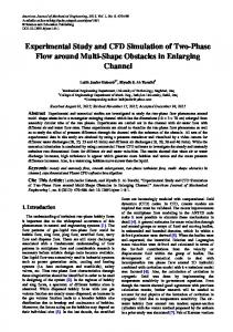
that the bubble formation degrades the separation performance. Finally, the accumulated particles are exhausted from the bottom of the outer pipe by the screw propeller mounted on the inner pipe. Figure 1 shows the schematic view of this separator. For this three-phase flow, a particle method is employed to model the motions of liquid, particle and air bubble by those of virtual particles. We use a MPS method as the base numerical procedure because of the simplicity and the relatively good predictability for liquid flow and free surface. In our modelling, different particles with different densities are assigned to particles representing liquid, particle and bubble. In the present study, as the first step of this research, we focus on the bubble formation region. Investigating the numerical results, it is confirmed that the bubble generation process is naturally and satisfactorily reproduced by the particle method proposed in the present study.
Figure1 Schematic view of nano-particle separator Numerical Procedures The MPS method proposed by Koshizuka et al. (1995) is adopted as the basic method of our computation because of the simplicity and the feasibility for liquid flow and free surface. The governing equations are incompressible Navier-Stokes equations. They can be expressed as (1) (2) In the MPS method, Navier-Stokes equation is divided into pressure part and other part as follows. (3) (4) Time derivation of Equation(1) can be expressed by (5) Then the continuity equation is given by (6) From Equations (3) to (6), the following equation 2
(7) 0 can be obtained. In this equation, the relation that density ρ is equal to constant density ρ with incompressible fluid is taken into account.
These governing equations of Navier-Stokes and continuity equations involve gradient and Laplacian operaters. In the MPS method, gradient and Laplacian models are prepared to solve the governing equations. The models can be given as follows (8) (9) where is physical quantity, d is number of dimension, rij is interparticle distance rij=xj-xi and subscripts I and j are the numbers for particle identification. ni is particle number density that is calculated by (10) and the particle number density calculated with initial particle position is n , and initial particle number density λ is calculated with regular particle position of initial state as follow 0
(11) wij is a weighting function and weights the interaction according to the interparticle distance rij. The weighting function wij is generally given by
(12) where re is influence radius. The closer particles are, the more influences take place between the particles with this weighting function. And particles having interparticle distance larger than influence radius re do not interact with each other. Two-stage algorithm is employed in the MPS method and the time step is divided into two stages. In the first stage, all terms of Equation(2) except pressure gradient term are calculated and the temporal velocities u* and positions x* of all particles are predicted. Then, the temporal values are corrected by pressure term, and the actual velocities uk+1 and positions xk+1 are obtained in the second stage. First, the value of Equation(4) is calculated with using Equation(9), and the temporal values are expressed as follows (13) (14) Then, the right-hand side of Equation(7) becomes 3
(15) where ni* is particle number density calculated from temporal values. Equation(15) is based on the concept that density is proportional to particle number density. Furthermore, by discretizing the lefthand side of Equation(7), pressure is calculated. At this time, pressure of the particles on the interface which satisfy (16) is fixed to zero. And, if there are particles having negative pressure, pressures of the particles are corrected to zero. Then, Equation(3) is obtained with using Equation(8), and finally the velocities uk+1 and positions xk+1 are calculated as follows (17) (18) It should be noted that the above-described MPS method has been well validated in various flows. In order to extend this MPS method to three-phase flows, firstly, we consider a liquid-gas twophase flow. A two-phase flow simulation with the MPS method is performed by dividing the pressure computation into two steps. This computational technique is employed to prevent gasphase particles from flying away (so-called explosion) by the continuous pressure gradient on the gas-liquid interface, and gas-phase and liquid-phase particles are calculated simultaneously with Equations(13) and (14). That is, in the first step, only liquid-phase particles are computed ignoring the gas-phase particles. At this time, pressures of the liquid-phase particles on the gas-liquid interface are fixed to the pressure of neighbouring gas-phase particle. In this way, the influences of gas-phase are transfer to the neighbouring liquid-phase particles. In the second step, the liquid particles that are computed in the first step are treated as wall particles, and only the gas-phase computation is carried out. By separating the liquid-phase and gas-phase calculation like this technique, it is not necessary to treat gas-phase and liquid-phase particles that have large density difference at the same time, and the instability of computation caused from the large density difference, that is a severe problem for twophase flow simulation with a MPS method, is completely avoided. Finally, a three-phase flow can be simulated by combining the two-phase flow simulation described above and the trajectory computation of solid particles. The particle trajectories are calculated with a Lagrangian approach. Solid particles are assumed to be spherical and irrotational. Gravity and hydrodynamic drag are considered as the forces acting on the solid particles. The motion equation of a solid particle is given as (19) where FG is gravitational force and FD is aerodynamic (hydrodynamic) drag acting on a solid particle from gas-phase (liquid-phase). The drag can be expressed as follow (20) (21) 4
(22) where CD is drag coefficient, Dp is particle diameter, Rep is particle Reynolds number and subscripts f and s represent fluid (gas or liquid) and solid, respectively. Computational Conditions In the present study, we conduct a numerical test for an air-bubble engulfment phenomenon with the gas-liquid-solid three-phase simulation procedure developed in the previous chapter. The computational conditions are listed in Table 1. Table 1 Computational conditions
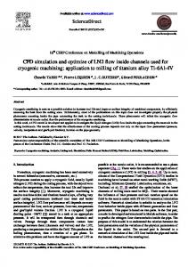
In the air-bubble engulfment phenomena, free-fallen solid particles from certain height impact on the gas-liquid interface and the air-bubbles are engulfed into the water, as illustrated in Figure 2. This situation mimics the phenomenon occurred in the advanced particle separator (see Figure 1). The computational domain is exhibited in Figure 2, and the depth of the water L = 0.36[m] is assumed. The materials are air as the gas-phase, water as the liquid-phase and diatom earth as the solid-phase.
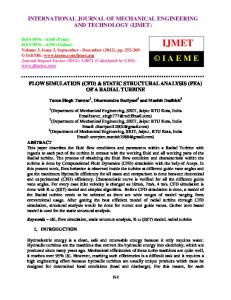
Figure 2 Schematic of air-bubble engulfment phenomenon Numerical Results and Discussion For the validation of the developed code, a dam break problem was simulated under the singlephase and the two-phase conditions. Figure 3 compare the numerical results for the temporal position of water front with the experimental data measured by Koashizuka et al. (1995). From this figure, the predicted behaviours of single-phase and two-phase simulation repreent the similar trend of the experiment. The difference between the single-phase and the two-phase simulations is derived from the maximum speed of interface. In the two-phase simulation, the maximum speed of interface is slightly larger than that of the single-phase one. In the two-phase simulation, there are gas-phase particles over the liquid-phase particles column and the liquid-phase particles are 5
accelerated more rapidly than the ones in the single-phase simulation at the earlier stage of dam breaking. In the same way, there are gas-phase particles between the interface and the right side wall, just before the liquid-phase particles reach the right side wall in the two-phase simulation. Because of these gas-phase particles, high pressure area is formed between the interface and the right side wall and liquid-phase particles decelerated more rapidly in the two-phase simulation than in the single-phase simulation. However, the global agreement is very good, and thus we confirmed that the developed code is sound.
Figure 3 Validation of two-phase simulation
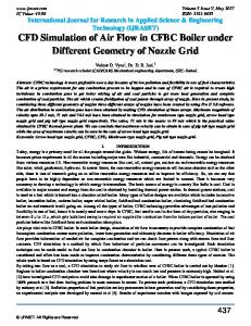
Figure 4 Engulfment of the air bubbles(red) into the water(yellow) by solid particle(blue) 6
The air-bubble engulfment phenomenon simulated with the gas-liquid-solid three-phase simulation is discussed here. The computational results are shown in Figure 4. Yellow, red, blue dots represent liquid-phase, gas-phase and solid-phase particles, respectively. In Figure 4, the engulfment of air bubbles are apparently observed. Also, the velocity changes of solid particles in gas and liquidphase is satisfactorily reproduced (not shown here). The solid particles free-fall in gas-phase, then reduce their velocities rapidly with impacting to the gas and liquid-phase interface and sink by the density difference of solid and liquid in the liquid-phase. Furthermore, the interface is deformed by the impacts of solid particles. The interface bursts at the moment of solid particle impact, then the gas-phase particles go into the void space of liquid-phase particles. In this way, air bubbles are engulfed into the liquid-phase. These phenomena are difficult to be duplicated with use of the traditional grid methods, and thus it is confirmed that our developed method has the ability to reproduce the interferences of gas, liquid and solid phases. However, the response of the light particles (i.e. air) to the faster heavy particles are not completely predicted, and some no-particle spaces can be found behind the solid particles in Figure 4. This defect should be improved in our future works. Summary In the present study, we developed a numerical method to simulate gas-liquid-solid three-phase flow, based of the MPS approach. We conducted some numerical tests with liquid single-phase, gas-liquid two-phase, gas-liquid-solid three-phase simulations. Those are the dam break problem with liquid single-phase and gas-liquid two-phase simulations and the air-bubble engulfment phenomenon with gas-liquid-solid three-phase simulation. In the dam break simulations, the code validation was fairly conducted, and both of the two computational results indicated reasonable agreement with the experimental results. In the air-bubble engulfment simulation, our numerical method reproduced the mutual interactions of gas, liquid and solid phases that are difficult to be predicted with the traditional grid methods. In our future works, we are planning to improve the present numerical method, especially for the occurrence of blank region behind a heavy particle, and apply it to the actual particle separator, in order to clarify the three-phase flow characteristics and improve the separator performance. References Koshizuka S., Tamako H. and Oka Y., ” A particle method for incompressible viscous flow with fluid fragmentation”, Computational Fluid Dynamics Journal, 4, 29-46, 1995 Krishna V., Sropriya R., Kumar V., Chakraborty S. and Meikap B.C., “Identification and Prediction of Air Core Diameter in a Hydro Cyclone by a Novel Online Sensor Based on Digital Signal Processing Technique”, Chemical Engineering and Processing: Process Intensification, 49(2), 165-176, 2010 Martin J.C. and Moyce W.J., “An experimental study of the collapse of liquid columns on a rigid horizontal plane”, Philos. Trans. Roy. Soc. London, Ser.A, 244, 312-324, 1952 Stairmand C.J., “The Design and Performance of Cyclone Separators”, Tans. Inst. Chemical Engineering, 29, 356-383, 1985
7