Multi user multiple-input multiple-output (MIMO) systems provide high ... is
equipped with multiple antennas and it is simultaneously. This work has been
partially ...
MULTI-USER MIMO DOWNLINK PRECODING FOR USERS WITH MULTIPLE ANTENNAS Veljko Stankovic and Martin Haardt Ilmenau University of Technology Communications Research Laboratory P.O. Box 100565, 98684 Ilmenau, Germany {veljko.stankovic, martin.haardt}@tu-ilmenau.de Phone: +49 (3677) 69-2613, Fax: +49 (3677) 69-1195 ABSTRACT Multi user multiple-input multiple-output (MIMO) systems provide high capacity with the benefits of space division multiple access. The channel state information at the base station (BS) or access point (AP) is very important since it allows joint processing of all users’ signals which results in a significant performance improvement and increased data rates. If the channel state information is available at the BS/AP, it can be used to efficiently eliminate or suppress multi-user interference (MUI) by beamforming or by using ”dirty-paper” codes. The precoding also allows us to perform most of the complex processing at the BS/AP which results in a simplification of users’ terminals. Linear precoding techniques have an advantage in terms of computational complexity. Non-linear techniques have a higher computational complexity and require some signaling overhead but can provide a better performance than linear techniques. In this paper we compare several linear and nonlinear techniques and propose two new schemes that outperform existing algorithms. The sensitivity of these proposed techniques to the channel estimation errors at the transmitter will be also analyzed. Index Terms - MIMO precoding, Block diagonalization, MMSE precoding, Tomlinson-Harashima precoding.
1. INTRODUCTION In recent years, there has been a considerable interest in wireless multiple-input, multiple output (MIMO) communications system because of their promising improvement in terms of performance and bandwidth efficiency. An important research topic is the study of multi-user (MU) MIMO system. Such systems have the potential to combine the high capacity achievable with MIMO processing with the benefits of space division multiple access. In the downlink scenario, a base station (BS) or an access point (AP) is equipped with multiple antennas and it is simultaneously This work has been partially performed in the framework of the IST project IST-2003-507581 WINNER, which is partly funded by the European Union. The authors would like to acknowledge the contributions of their colleagues.
transmitting to a group of users. Each of these users is also equipped with multiple antennas. Motivated by the need for cheap mobiles with low power consumption, we focus on systems where the complex signal processing is performed at the BS/AP. The BS/AP will use the channel state information (CSI) available at the transmitter to allow these users to share the same channel and mitigate or ideally completely eliminate multi-user interference (MUI) by intelligent beamforming or by the use of ”dirty-paper” codes. All precoding techniques can be classified by the amount of the MUI they allow (as zero or non-zero MUI techniques) and linearity (as linear and non-linear techniques). Linear precoding techniques require no overhead to provide the mobile the demodulation information and are less computationally expensive than non-linear. However, non-linear techniques can provide much higher capacity. Block diagonalization (BD) is a linear pre-coding technique for the downlink of MU MIMO systems [1]. It decomposes a MU MIMO downlink channel into multiple parallel independent single-user MIMO downlink channels. The signal of each user is pre-processed at the transmitter using a modulation matrix that lies in the null space of all other users’ channel matrices. Thereby, the MUI in the system is efficiently set to zero. BD can be used with any other previously defined single-user MIMO technique [2], as the different users do not interfere with each other. BD is attractive if the users are equipped with more than one antenna. However, the zero MUI constraint can lead to a significant capacity loss when the users’ subspaces significantly overlap. Another technique also proposed in [1], named successive optimization (SO), addresses the power minimization and the near-far problem and it can yield better results in some situations but its performance depends on the power allocation and the order in which the users’ signals are preprocessed. The zero MUI constraint is relaxed and a certain amount of interference is allowed. Tomlinson-Harashima precoding is a non-linear pre-coding
technique developed for single-input, single-output (SISO) multipath channels. Recently it has been also proposed for the equalization of MUI in MIMO systems [3], where it performs spatial pre-equalization instead of temporal, for ISI channels. Minimum mean-square-error (MMSE) precoding in combination with THP is proposed in [4]. MMSE balances the MUI in order to reduce the performance loss while the THP is used to eliminate the part of the MUI and improves the diversity. However, for two closely spaced antennas, as in the case when the user is equipped with multiple antennas, the inter-stream interference mitigation still causes some performance loss. This paper is organized as follows. In Section 2, we describe the MU downlink channel. In Section 3, we describe the precoding techniques that will be compared and in Section 4, we present the results of the simulations. A short summary follows in the Section 5. 2. SYSTEM MODEL We consider a MU MIMO downlink channel where MT transmit antennas are located at the base station, and MRi receive antennas are located at the i-th mobile station (MS), i = 1, 2, . . . , K. There are K users (or MSs) in the system. The total number of receive antennas is MR =
K X
MRi
i=0
We will use the notation {MR1 , . . . , MRK } × MT to describe the antenna configuration of the system. We assume a flat fading channel. The MIMO channel to user i is denoted as Hi ∈ CMRi ×MT . Moreover, the combined channel matrix is given by � �T T H = H1T H2T · · · HK .
In order to take into account channel estimation errors we use a ”nominal-plus-perturbation” model. The estimated combined channel matrix can be represented as c=H +E H
where H denotes the flat fading network channel matrix, and E is a complex random Gaussian matrix distributed ac� cording to CN 0MR ×MT , MR σn2 IMT . 2 2 Let ρ = kHk / kEk be the SNR of the channel state information at the transmitter. 3. MULTI-USER PRECODING In this section we will briefly describe BD, SO, MMSE THP and propose two new techniques, the combination of SO and THP precoding and successive MMSE precoding (SMMSE).
3.1. Block diagonalization (BD) Block diagonalization was first proposed in [1]. It is restricted to channels where the number of transmit antennas MT is greater or equal to the total number of receive antennas in the network MR . Let us define the precoder matrices as � � F = F1 F2 · · · FK ∈ CMT ×r (1)
where Fi ∈ CMT ×ri is the i-th user’s precoder matrix. Moreover, r ≤ MR is the total number of the transmitted data stream sequences, while ri ≤ MRi is the number of data stream sequences transmitted to the i-th user. We can find the optimal precoding matrix F such that all MUI is zero by choosing a precoding matrix Fi that lies in the null space of the other users’ channel matrices. Thereby, a MU MIMO downlink channel is decomposed into multiple parallel independent SU MIMO channels [5], [2]. fi as If we define H �T � T T fi = H1T · · · H T Hi+1 · · · HK (2) H i−1 the zero MUI constraint forces Fi to lie in the null space of fi . From the singular value decomposition (SVD) of H fi H ei whose rank is L fi = U ei Σ ei H
h
(1) Vei
(0) Vei
iH
(3)
e i singular vectors we choose the last right MT − L e (0) Vei ∈ CMT ×MT −Li which form an orthogonal basis for fi . The equivalent channel of user i after the null space of H (0) eliminating the MUI is identified as Hi Vei , whose dimene i ) and is equivalent to a system sion is MRi × (MT − L e with MT − Li transmit antennas and MRi receive antennas. Each of these equivalent SU MIMO channels has the same properties as a conventional SU MIMO channel. Define the SVD iH h (0) (4) Hi Vei = Ui Σi Vi(1) Vi(0)
and let the rank of the i-th user’s equivalent channel ma(1) trix be Li . The product of the first Li singular vectors Vi (0) and Vei produces an orthogonal basis of dimension Li and represents the transmission vectors that maximize the information rate for user i subject to the zero MUI constraint. 3.2. Successive optimization (SO) As mentioned before, by applying BD on the combined channel matrix of all users the MU MIMO channel can be transformed into a set of parallel single-user MIMO channels. However, there is a capacity loss due to the nulling of overlapping subspaces of different users. In [1], the authors propose a successive precoding algorithm in order to define a
simplified solution of the power control problem. By allowing a certain amount of interference, this algorithm reduces the capacity loss due to the subspace nulling. First, we have to assume or determine a certain optimum ordering of the users, similar to VBLAST [6] or MMSE THP [4]. Using SO, the modulation matrix for each user is designed in such a way that it lies only in the null space of the channel matrices of previous users. As a consequence, only they will generate the interference to this user. Let us define the previous i − 1 users’ combined channel matrix as ci = H
�
H1T
H2T
···
T Hi−1
and its corresponding SVD as bi ci = U bi Σ H
h
(1) Vbi
(0) Vbi
iH
�T .
(5)
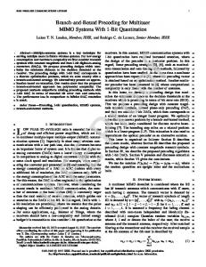
ci is Lˆi , then Vb (0) contains MT − Lˆi right If the rank of H i singular vectors. As in the BD solution, we force the modci by setting ulation matrix Fi to lie in the null space of H (0) ′ ′ Fi = Vbi Fi for some choice of Fi . Thereby, the i-th user does not see any interference from any subsequent user (i + 1, . . . , K). 3.3. Combination of SO and THP In this section we will describe how to combine SO and THP, in order to improve the use of the available subspace of different users and eliminate any residual MUI. The resulting equivalent channel matrix is also block diagonal which facilitates the definition of an ordering algorithm of the users. The combination of SO and THP (SO THP) is performed by successively calculating first BD, then the reordering of users, and in the end precoding with THP. Here, instead of examining all K! ordering possibilities which minimize the total capacity loss in the system, we make the heuristic simplification to minimize the capacity loss of each user separately. In short, we first calculate the maximum capacity that an individual user can achieve. Then, we identify the user with the smallest difference between its maximum capacity and its BD capacity and generate its precoding matrix such that it lies in the null space of the remaining users’ channel matrices. Afterwards, we form the new combined channel matrix without this user’s channel matrix. We repeat these steps until the combined channel matrix is empty. The order of the users in which they are precoded using THP is the reverse of the order in which their precoding matrices are generated. With the reordering of the users in the reverse order of precoding we achieve that the equivalent combined channel matrix after precoding and demodulation is lower block diagonal with the singular values on the main diagonal. The
n
modulo operator
F
MOD
H
modulo operator
D
-1
diag([DHF]ii)
MOD
B transmitter
channel
receiver
Fig. 1. Block diagram of the SO THP system. lower triangular feedback matrix, used in THP precoding [4], is generated from this equivalent combined channel matrix after the elements in each row are divided by the elements on the main diagonal, i.e., the corresponding singular values. In Fig. 1. we show the block diagram of the SO THP system. The individual user’s channel matrices and demodulation matrices are grouped in matrices H and D. The feedback matrix B, generated in the last step of the SO THP algorithm is now used to precode the users’ data streams starting with the data stream of the first user whose precoding matrix F1 had been generated last. By using THP at the transmit side we significantly increase the transmit power. Therefore we introduce the modulo operator at the transmitter and the receiver in order to reduce the constellation size into certain boundaries. Before applying the modulo operator at the receiver we divide each data stream by the corresponding singular value so that the constellation boundaries at the receiver are the same as at the transmitter. The ordering algorithm described here forces the modulation matrix of the user that in the current step has minimum capacity loss to lie in the null space of the remaining users’ channel matrices. 3.4. MMSE THP transmit pre-coding The linear Wiener transmit filter is defined by the following equation: F = β H H H + αIMT where β=
s
PT , tr (F xxH F H )
α=
�−1 �
HH
PT MR σn2
(6)
�−1
,
PT denotes the available transmit power, x is a data vector and σn2 denotes the variance of the zero mean circularly symmetric complex Gaussian (ZMCSCG) noise. In [4] the authors describe a system combining THP with MMSE pre-coding to eliminate a part of the MUI that is below the main diagonal of the equivalent network channel matrix. The algorithm described in [4] is iterative and requires a certain ordering of the users. First, a precoding matrix F is defined column by column starting from user K. The column corresponding to the i-th user is obtained as the
3.5. Successive MMSE transmit precoding (SMMSE) MMSE precoding can improve the system performance by introducing a certain amount of interference especially for users equipped with a single antenna. However, it suffers a performance loss when it attempts to mitigate the interference between two closely spaced antennas as in the case when the user terminal is equipped with more than one receive antenna. Here we propose a new algorithm that deals with this problem by successively calculating the columns of the precoding matrix F for each of the receive antennas separately. The columns in the precoding matrix Fi in equation (1), each corresponding to one receive antenna, are calculated successively. For the i-th user, i = 1, . . . , K, and j-th re¯ (j) ceive antenna j = 1, . . . , MRi we define the matrix H i as: hTi,j H1 .. . (j) ¯ Hi = Hi−1 Hi+1 .. . HK
where hTi,j is the j-th row of the i-th user’s channel matrix Hi . The corresponding column of the precoding matrix Fi is equal to the first column of the following matrix: � �−1 ¯ (j) H H ¯ (j) + αIM ¯ (j) H H Fi,j = β H T i i i
(7)
After calculating the beamforming vectors for all receive antennas in this fashion, the equivalent combined channel matrix of all users is equal to HF ∈ CMR ×MR after the precoding. For high SNR ratios, this matrix is also block diagonal. We can now apply any other previously defined SU MIMO technique on the i-th user’s equivalent channel matrix Hi Fi . After the precoding using matrix Fi , we first perform the singular value decomposition (SVD) and then, if we want to maximize the capacity of the system use waterpouring (WP) on the eigenmodes of all users or if we want to extract the maximum diversity and array gain, we transmit only on the dominant eigenmode. Dominant eigenmode transmission (DET) can provide maximum SNR at the receiver and minimum BER performance. The complexity of this algorithm is only slightly higher than the one of BD. By using this algorithm we efficiently improve the system
20 TDMA {2,2}×4 MMSE THP {1,1,1,1}×4 SO THP {1,1,1,1}×4 ZF {1,1,1,1}×4
18 16
10 % Outage Capacity
i-th column of the precoding matrix calculated using only the first i rows of the network channel matrix H and equation (6). After this, THP is used to eliminate the MUI to the i-th user originating from the previous i − 1 users. The detailed description of the algorithm can be found in [4].
14 12 10 8 6 4 2 0
0
5
10
15
20
SNR [dB] r
Fig. 2. 10 % outage capacity as a function of receive SNRr . performance by introducing MUI and by eliminating interstream interference. 4. SIMULATION RESULTS In this section we compare the performance of SO THP, minimum mean-square-error (MMSE) THP transmit filtering proposed in [4], and SMMSE precoding. The channel H is assumed to be spatially white and flat fading. First, we use the complementary cumulative distribution function (CCDF) and a 10% outage capacity to compare the system with configuration {1, 1, 1, 1} × 4 employing MMSE THP pre-filtering to a system employing SO THP with the configuration {1, 1, 1, 1} × 4. The capacity is calculated using the results on the capacity of MIMO broadcast channels in [7]. We also present capacity results for a TDMA system as a comparison. We employ the following transmit and receive SNR definitions, respectively: � � � � PT PT and SNRr = 10 log10 . SNRt = 10 log10 MR σn2 σn2 In Figures 2 and 3 we compare these techniques using 10% outage capacity as a function of receive SNR and the number of transmit antennas MT . In Fig. 2 we show that for high SNR ratios SO THP provides a higher capacity than MMSE THP. However, at low SNR ratios MMSE THP has an advantage over SO THP when the users are equipped with only one antenna. The zero forcing (ZF) solution is equal to the pseudo-inverse of the combined channel matrix for all users. ZF has all the drawback of having zero MUI constraint and fighting the inter-stream interference of two closely spaced antennas. For antenna configuration {1, 1, 1, 1} × 4 SO THP has 40% higher capacity than a TDMA system.
{2,2,2}×6
−1
16
10 TDMA {2,2}× M
T
15
MMSE THP {1,1,1,1}× M
T
SO THP {1,1,1,1}× M
T
−2
10
13 12 −3
10 11
BER
10 % Outage Capacity
14
10
−4
SO THP ρ = 20 dB BD ρ = 20 dB SMMSE ρ = 20 dB MMSE THP ρ = 20 dB
10
9 8
−5
7 6
10 4
4.5
5
5.5
6
6.5
7
7.5
8
Number of transmit antennas − M
T
Fig. 3. 10 % outage capacity as a function of the number of transmit antennas MT . SNRr = 10dB
The BER performance of the proposed SO THP and SMMSE precoding techniques and BD are shown in Fig. 4. We compare the performance of these techniques in case when the users are equipped with multiple antennas. BD is a linear precoding technique that has a zero MUI interference constraint. By introducing MUI, SMMSE provides a higher both diversity and array gain than BD. SO THP does not have the same diversity gain as BD, that can be explained with the influence of the modulo operator used in THP. In Fig. 5 we compare the BER of the various previously described techniques in a mixed system where we have both single- and multiple- antenna users. The system has the configuration [1, 1, 2, 2] ×6. This figure illustrates that SO THP can provide the highest performance. SO THP has the same performance at high SNR ratios as MMSE THP. For low SNR, SMMSE performs also very well but does not have the same diverity gain as SO THP and MMSE THP. However, we would like to emphasize that this technique is linear and does not require any signaling from the BS/AP to the users. The real advantage of this technique can be seen when all the users are equipped with multiple antennas as shown in Fig. 4. In this case we see that SMMSE outperforms both BD and MMSE THP which is a nonlinear technique. Also we should note that although BD has better performance than SO THP for multiple antenna users, in a mixed scenario SO THP outperforms BD, because BD performs poorly when users are equipped with only one antenna. In Fig. 6. we show the CCDF function of the capacity of the systems employing BD and SMMSE. For the configuration {1, 1, 1, 1} × 4, SMMSE reduces to linear MMSE precoding. By abandoning the zero MUI constraint SMMSE gains over 2 bits/sec/Hz compared to BD when the users are equipped with multiple antennas. In our simulations we
−6
10
0
2
4
6
8
10
SNR [dB] t
Fig. 4. BER performance comparison of MMSE THP in configuration [1, 1, 1, 1, 1, 1] × 6 and BD and SMMSE in configuration [2, 2, 2] × 6.
use water-poring (WP) power loading. 5. CONCLUSION In this paper we analyze the performance of different transmit precoding techniques in a downlink multi-user scenario. Depending on the set of constraints, like the size of the overhead or the amount of the MUI allowed, different techniques can be optimal. Linear techniques are computationally less expensive and generally require no signaling overhead. On the other hand, the non-linear techniques can provide better performance. The first technique that we propose in this paper is the combination of a linear pre-coding technique called successive optimization and a non-linear technique called Tomlinson-Harashima precoding. By combining these two techniques we are able to completely eliminate MUI in the system when there is perfect CSI available at the transmitter. The equivalent channel matrix is block diagonal after precoding. This technique is especially attractive in cases when the users and the base station/access point are equipped with multiple antennas. In these cases SO THP provides the same capacity as, for example, MMSE THP but without any MUI. By transmitting only on the dominant eigenmodes of each user, SO THP can provide a better BER performance than MMSE THP for low SNR ratios. This advantage is particularly important when we do not have perfect CSI at the transmitter. SO THP is less sensitive to channel estimation errors and can give better results than MMSE THP. In this paper we also introduced a linear technique that performs successive MMSE prefiltering in order to reduce
SNR = 10 dB
{1,1,2,2}×6
−1
r
10
1 SMMSE {2,2}×4 MMSE {1,1,1,1}×4 BD {2,2}×4 BD {1,1,1,1}×4 ZF {1,1,1,1}×4
0.9 0.8
−2
10
0.7
CCDF
BER
0.6 −3
10
BD DET ρ = 20 dB MMSE THP ρ = 20 DB SMMSE ρ = 20 dB SO THP ρ = 20 dB
−4
10
−5
10
0
2
0.5 0.4 0.3 0.2 0.1
4
6
8
10
SNR [dB] t
Fig. 5. BER performance comparison of MMSE THP [1, 1, 1, 1, 1, 1] × 6 and BD, SO THP and SMMSE in configuration [1, 1, 2, 2] × 6. the performance loss due to the zero MUI constraint and the cancellation of the interference between the antennas located at the same terminal. SMMSE outperforms BD, another linear precoding techniques that also performs well when the users are equipped with multiple antennas but with zero MUI. Moreover, in a system, where all users are equipped with multiple antennas, SMMSE outperforms both SO THP and MMSE THP that are non-linear precoding techniques. SMMSE has relatively low computational complexity and reduces the overhead needed for demodulation. For high SNR ratios it also results in a block diagonal combined network channel matrix and it can be combined with any other previously proposed precoding technique. It is expected that the further investigations will show that the combination of SMMSE and THP can perform even better. In a mixed scenario, where the users are equipped with various number of antennas, SO THP has the best performance. For low SNRs, SMMSE also performs well but has smaller diversity than SO THP. Although BD has similar performance as SO THP for multiple-antenna users, SO THP has the advantage of providing a good performance to the single-antenna users also. For high SNR ratios, SO THP provides almost twice the capacity as a TDMA system with the same number of antennas. 6. REFERENCES [1] Q. Spencer and M. Haardt, “Capacity and downlink transmission algorithms for a multi-user MIMO channel,” in Proc. 36th Asilomar Conf. on Signals, Systems, and Computers, Pacific Grove, CA, IEEE Computer Society Press, November 2002.
0
0
2
4
6
8
10
12
14
16
C
Fig. 6. CCDF of the capacity of the BD, SMMSE, and ZF system. [2] L. U. Choi and R. D. Murch, “A transmit preprocessing technique for multiuser MIMO systems using a decomposition approach,” IEEE Transactions on Wireless Communications, vol. 3, no. 1, pp. 20–24, January 2004. [3] G. Cinis and J. Cioffi, “A multi-user precoding scheme achieving crosstalk cancellation with application to DSL systems,” in Proc. Asilomar Conf. on Signals, Systems, and Computers, November 2000, vol. 2, pp. 1627–1637. [4] M. Joham, J. Brehmer, and W. Utschick, “MMSE approaches to multiuser spatio-temporal Tomlinson-Harashima precoding,” in Proc. 5th International ITG Conference on Source and Channel Coding (ITG SCC’04), January 2004, pp. 387– 394. [5] Q. H. Spencer, A. L. Swindlehurst, and M. Haardt, “Zeroforcing methods for downlink spatial multiplexing in Multiuser MIMO channels,” IEEE Transactions on Signal Processing, vol. 52, no. 2, pp. 461–471, February 2004. [6] P.W. Wolniansky, G.J Foschini, G.D. Golden, and R.A. Valenzuela, “V-BLAST: An architecture for realizing very high data rates over the rich-scattering wireless channel,” in Proc. ISSSE 98, September 1998. [7] S. Vishwanath, N. Jindal, and A. J. Goldsmith, “On the capacity of multiple input multiple output broadcast channels,” in Proc. of the IEEE International Conference on Communications (ICC), New York, NY, April 2002.