lator1 or on the joint-transform correlator JTC,2,3 deal with monochromatic images. In real images the color information is sometimes a fundamental component ...
Multichannel single-output color pattern recognition by use of a joint-transform correlator Meir Deutsch, Javier Garcı´a, and David Mendlovic
A novel method for performing color image recognition by the use of the coherent joint-transform correlator is introduced. The input plane of the proposed method is a spatial rearrangement of the separation into color channels of both the color input scene and the color target. This input plane is gray scaled and monochromatic, thus it can be displayed by the use of amplitude spatial light modulators to achieve real-time operation. The system provides a single output-plane result of the optical coherent addition of the separate channels’ correlation outputs. At the output plane no electronic postprocessing is needed, and the detection decision is achieved simply by the application of threshold detection. Experimental results and computer simulations are presented to demonstrate the abilities of this system. © 1996 Optical Society of America
1. Introduction
One of the main trends in optics has been that concerning pattern recognition as a result of the ability of an optical system to perform a correlation in real time. However, most of the optical implementations, based either on the 4-f VanderLugt ~VL! correlator1 or on the joint-transform correlator ~JTC!,2,3 deal with monochromatic images. In real images the color information is sometimes a fundamental component for image analysis. The inclusion of color information in an opticalcorrelator scheme has become increasingly important, especially because of the wide spread of electronic image-acquisition devices ~such as color CCD cameras!. These devices typically capture a color image by grabbing several color channels @typically red, green, and blue ~RGB! channels# simultaneously, either by the use of bandpass filters on the detector or by the use of different detectors for each band. This process converts a color image into a set
M. Deutsch and D. Mendlovic are with the Faculty of Engineering, Department of Electrical Engineering–Physical Electronics, Tel-Aviv University, Tel Aviv 69978, Israel. J. Garcı´a is with the Department Interuniversitari d’Optica, Universitat de Valencia, Burjassot 46100, Spain. Received 19 January 1996; revised manuscript received 19 June 1996. 0003-6935y96y356976-07$10.00y0 © 1996 Optical Society of America 6976
APPLIED OPTICS y Vol. 35, No. 35 y 10 December 1996
of intensity-information images, representing a few separate color channels defined by the transmittance of the color image for a set of predefined wavelengths. Although the three RGB color channels are satisfactory for the human color-perception system, other applications such as remote sensing may require extra channels, usually infrared channels. The concept of separation into color channels led to the development of multichannel optical color pattern-recognition systems. The multichannel methods perform the correlation process in parallel for all the color channels that compose the image by the utilization of coherent optical correlators that are illuminated simultaneously with a few coherent sources, each having a different wavelength. The output plane consists of a set of superimposed correlation distributions, one for every channel and each with a different wavelength, that must be analyzed independently and composed together to render the detection decision. The multichannel method was implemented both for the VL correlator and the JTC by the spatial separation of the spectra of each color channel in the Fourier plane with a dispersive element located at the input plane.4 –7 A different implementation method for the VL correlator that uses a single matched filter was also introduced.8,9 The multichannel approach can also be implemented by the use of time-multiplexing the different color channels ~instead of the above-mentioned wavelength multiplexing! in a monochromatic coherent correlator.10,11
This way, by time-integrating the output plane, we obtain a single correlation distribution directly. A single correlation output can also be obtained by the representation of the color image by the use of only a single information channel ~instead of the usual three channels!. This method encodes the color image as a phase-only distribution for a VL correlator or JTC.12,13 Hence the system and the output analysis are simplified at the expense of the preprocessing necessary to obtain the color-phase encoding of the input plane. In this paper we propose a novel method for color pattern recognition that is based on the classical JTC architecture. In this method the color image is separated into the RGB color channels and displayed on a single, monochromatic, input plane, resulting in a single correlation output. The input plane is gray scaled; thus, real-time operation is possible with the use of spatial light modulators. The detection decision is achieved simply by the application of a threshold in the output plane, without any electronic postprocessing. Section 2 contains a description of the principles of multiple-input-object JTC’s, and this forms the basis for the proposed method, which described in Section 3. Sections 4 and 5 provide the computer simulations and experimental results, respectively. 2. Multiple-Input-Object Joint-Transform Correlator
The VL correlator, which involves complex spatialfilter synthesis, is in principle not suitable for realtime operation owing to the presence of a matched filter. Moreover, it requires a relatively accurate alignment of the spatial filter, resulting in a nonrobust system. On the other hand, the JTC has become popular in recent years owing to the possibility of real-time implementation14,15 and its overall simplicity. The original JTC configuration2,3 is used to perform a correlation between only two input objects—an input scene and a target, placed side by side in the input plane. However, to better utilize the large space– bandwidth product of the JTC input plane and to use the parallel nature of optics, many researches have proposed a JTC setup capable of performing several elementary correlations simultaneously. The general JTC case involves an input plane composed of multiple input scenes and multiple targets. Usually, researchers have concentrated on the problem of an input plane containing a single input scene and multiple targets,16 –18 although the case of multiple input scenes and a single target has also been investigated.19 Both cases require that the cross correlations at the output plane between every input scene and every target will be distinct and will not overlap with each other or with other correlation terms ~autocorrelation terms and cross correlations between any pair of either input scenes or targets!. This requirement will not be fulfilled unless the input scenes are placed sufficiently far from the targets. Let us consider a general case of an arrangement of N objects ~either input scenes or targets! at the input
plane of a JTC. The input plane p~x, y! is represented by N
p~x, y! 5
( f ~x 2 a , y 2 b !, K
K
(1)
K
K51
where ~aK, bK! is the position of the object fK~x, y! at the input plane. The intensity distribution I~j, h! at the joint-spectrum plane is
U(
U
2
N
I~j, h! 5
FK~j, h!exp@2i~jaK 1 hbK!#
K51
(2)
N
5
( uF ~j, h!u
2
K
K51 N
N
( ( F ~j, h! F *~j, h!
1
K
J
K51 J51 JÞK
3 exp@ij~aJ 2 aK! 1 ih~bJ 2 bK!#, where the asterisk denotes the complex conjugate. FK~j, h! is the Fourier transform of the object fK and ~j, h! are the spatial-frequency coordinates at the joint-spectrum plane. After the second Fourier transform, the field distribution at the output plane O~ x9, y9! is given by N
O~x9, y9! 5 N
1
(C
KK
~x9, y9!
K51 N
((C
KJ
@ x9 2 ~aJ 2 aK!, y9 2 ~bJ 2 bK!#,
(3)
K51 J51 JÞK
where the correlation CKJ between the objects fK and fJ is defined as CKJ~x9, y9! 5
**
fK~x, y! fJ*~x 2 x9, y 2 y9!dxdy.
(4)
In Eq. ~3!, the first term on the right-hand side is the sum of all the autocorrelation distributions of the input objects; it appears at the center of the output plane. The second term represents the cross correlations between any pair of input objects. These cross-correlation distributions appear in the output plane at locations that depend on the distances, at the input plane, between the objects participating in each cross-correlation term. Hence, depending on the arrangement of the objects at the input plane, overlapping of the cross-correlation distributions at the output plane may occur. Note that the output plane is symmetric with respect to the main axes origin because the joint-spectrum plane, after the squarelaw conversion, is real, i.e., O~x9, y9! 5 O~2x9, 2y9!.
(5)
The previous work on multiple-input-object JTC’s16 mentioned above uses input-object arrangements that generate the desired cross-correlation terms as separate and nonoverlapping distributions. In Section 3 we use the concept of multiple-input-object JTC’s from a different point of view, utilizing the 10 December 1996 y Vol. 35, No. 35 y APPLIED OPTICS
6977
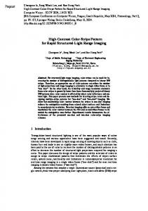
Fig. 1. Arrangement of the input plane for the multichannel, single-output color JTC.
overlap of the cross-correlation terms to achieve color pattern recognition. 3. Multichannel Single-Output Color Joint-Transform Correlator
We propose to utilize the multiple-input-object JTC configuration together with the multichannel colorseparation principles to provide real-time color pattern recognition. Color pattern recognition involves the detection of multiple input scenes and multiple targets ~one scene–target pair for each color channel involved!. It could be possible to find an arrangement of objects at the input plane that would lead to the spatial separation of the cross correlations obtained for every scene–target color channel. However, we assume that a superposition of the correlations for every color channel is a more useful approach. To achieve that, we arrange the objects in the input plane as shown in Fig. 1. This input plane is monochromatic and consists of six gray-scale objects. The three objects in the left side of the input plane are the three RGB color channels ~ fR, fG, and fB, respectively! of the color input scene. The corresponding RGB color channels ~tr, tg, and tb, respectively! of the color target are placed in the righthand side of the input plane. Hence the input plane can be expressed as p~ x, y! 5 tr~x 2 a0, y 2 b0! 1 tg~x 2 a0, y! 1 tb~x 2 a0, y 1 b0! 1 fR~x 1 a0, y 2 b0! 1 fG~x 1 a0, y! 1 fB~x 1 a0, y 1 b0!.
(6)
The output plane of the JTC is shown in Fig. 2. It is the graphic representation of the terms of Eq. ~3! with N 5 6. There exist at the output plane 36 correlation terms grouped in 15 correlation locations, each location consisting of the coherent addition of a few overlapping cross-correlation terms. The out6978
APPLIED OPTICS y Vol. 35, No. 35 y 10 December 1996
Fig. 2. Locations of the correlation terms at the output plane. Capital letters in a correlation term refer to the color channels of the input scene; lowercase letters represent those of the target.
put plane is seen to be symmetric with respect to the main axes origin, as expected from Eq. ~5!. The separation between the objects at the input plane is necessary for achieving an output plane as shown in Fig. 2 ~i.e., without overlap between any correlation locations!. Thus we require Sx $ Dx,
Sy $ Dy,
(7)
where Sx is the horizontal separation between the input-scene color channels and the target color channels and Sy is the vertical separation between the color channels of the input scene. The terms ~dx, dy! and ~Dx, Dy! are the vertical and horizontal sizes of the color target and the color input scene, respectively ~see Fig. 1!. We assume that the size of the input scene is larger than or equal to the size of the target. The correlation locations that are of interest for the proposed method are the areas around ~22a0, 0! and ~2a0, 0!, and they represent the coherent addition of the three cross-correlation terms between the corresponding RGB color channels of the target and the input scene. The correlation location around ~22a0, 0! has a field distribution of the form CrR 1 CgG 1 CbB 5 tr ^ fR 1 tg ^ fG 1 tb ^ fB,
(8)
where the symbol ~R! denotes correlation. The subscripted letters of the correlation terms denote the
Fig. 3. Setup for a real-time, multichannel, single-output color JTC.
objects participating in the correlation term: Capital letters refer to the color channels of the input scene, whereas lowercase letters stand for the color channels of the target. The expression in Eq. ~8! is used, directly after the application of a threshold, as the decision function for detection of the color target in the color input scene. We obtained, optically, the composition of the cross-correlation distributions for all three RGB color channels into a single output function; hence no postprocessing in the output plane is needed. The detector at the output plane located around ~22a0, 0! detects the intensity of the field distribution in Eq. ~8!, resulting in an intensity distribution expressed by uCrR 1 CgG 1 CbBu2 5 uCrRu2 1 uCgGu2 1 uCbBu2 1 2CrRCgG 1 2CgGCbB 1 2CrRCbB.
(9)
The correlation performance of this intensity distribution is superior when compared with that of the addition of intensities used in other multichannel methods. The last three terms in Eq. ~9! are multiplication terms that enhance the peak value and decrease the sidelobes, hence resulting in a sharper correlation peak. This optical composition decreases the probability of false alarms and, as the computer simulations show, can produce detection even in cases for which the composition of colorchannel intensities fails. An experimental setup that is capable of performing this multichannel, single-output color JTC operation in real time is shown in Fig. 3. This setup is the conventional JTC configuration with a liquidcrystal light valve ~LCLV! at the joint-spectrum plane. The readout beam of the LCLV is proportional to the intensity of the joint spectrum. The input plane is an amplitude-only liquid-crystal television ~LCTV! displaying, as a gray scale, the RGB color channels for both the color input scene and the color target. The optically composed correlation distribution is achieved at the output plane around the 11 and 21 diffraction orders on the X9 axis. 4. Computer Simulations
We simulated a JTC setup that utilizes the multichannel, single-output method proposed in this paper. The color input scene was a scanned version of
a postal stamp ~see issue cover! of size 140 3 100 pixels and having 164 different colors. This stamp shows three different butterflies ~different in both shape and color! camouflaged in color clutter. The color target was the upper butterfly, which has a size of approximately 40 3 50 pixels. The gray-scale representations of the RGB color channels for the input scene and the target ~shown in Fig. 4! were arranged in a 512 3 512 pixel input plane, according to Eq. ~6!. The separation between the objects in the input plane was determined according to condition ~7!. However, because of the periodic nature of the discrete Fourier transform, it was also necessary to ensure adequate borders in the input plane to prevent overlap between the correlations in the borders of the output-plane matrix. To demonstrate the gain obtained by the optical addition of several color channels we performed simulations for the proposed method by using all three RGB color channels ~input plane composed of six objects!. In addition, simulations were performed with the use of only two color channels ~either RG, GB, or RB, with an input plane composed of four objects! and with only a single color channel ~either R, G, or B, with an input plane composed of two objects!. In all seven cases ~see the left-hand column of Table 1!, the region of interest ~size, 180 3 150 pixels! at the output plane was located around ~22a0, 0!. The results of the computer simulations are given in the righthand column of Table 1. The results listed in Table 1 give the minimum threshold value ~in percent! at the output plane for which the only visible area in the region of interest is the true correlation peak. The cases for which the true correlation peak was lower than for other pixels in the region of interest were denoted as cases of impossible detection. Figure 5 shows a three-dimensional plot of the region of interest at the output plane for the proposed method ~see first row of Table 1!. It can be seen that the correlation peak is quite distinctive and sharp, in spite of the clutter noise. Table 1 shows that detection based on only a single color channel is impossible for the R or G channel as a result of the dominant color clutter in these two channels, and it is barely possible for the B channel. As we add more color channels to the input plane, the detection capability is improved. When either one of these two low10 December 1996 y Vol. 35, No. 35 y APPLIED OPTICS
6979
Fig. 4. Gray-scale representations of the separation into the RGB color channels for the input scene and the target, respectively: ~d! show the red ~R! channel; ~b! and ~e! show the green ~G! channel; ~c! and ~f ! show the blue ~B! channel.
~a! and
performance color channels is added to the B channel ~producing the RB or GB case!, the minimum detection-threshold value is lowered, and detection is possible. The case combining both the R and G color channels ~RG case! still does not produce detection, although the false-alarm peak value is lowered, and detection is nearly possible. When both the R and G color channels are added to the B channel, detection is possible, and the minimum detection-threshold value is lowered less than 40%.
Table 1. Correlation-Simulation Results for the Seven Combinations of Color Channels: Minimum Detection-Threshold Values Applied in the Region of Interest at the Output Plane
6980
Color Channels Used at the Output Plane
Minimum Detection Threshold
RGB RG GB RB R G B
38% Detection impossible 44% 60% Detection impossible Detection impossible 87%
APPLIED OPTICS y Vol. 35, No. 35 y 10 December 1996
Fig. 5. Computer-simulation results for the input scene and target of Fig. 4 showing a three-dimensional plot of the region of interest at the output plane for the proposed method.
Fig. 6. Experimental results showing the intensity distribution at output plane of the JTC for the input scene and target of Fig. 4. The region of interest is marked with a rectangle.
For comparison, we simulated the conventional multichannel pattern-recognition systems ~on the basis of digital manipulation of the correlation intensities of every color channel! using the same color scene and target. By using a decision algorithm that assumes a true target detection only if a correlation peak appears simultaneously in all three ~R, G, and B! channels,20 one can produce true detection by applying a threshold value ~assuming the same threshold value in all three channels! ranging from 31% to 65%. Lower threshold values will produce false alarms, whereas higher threshold values will not detect the target. A different type of decision algorithm20 based on thresholding the sum of the correlation intensities for every color channel can produce true detection only for threshold values higher than 74%. Thus, both of the abovementioned conventional multichannel methods provide a smaller and more limited range of detection-threshold values compared with the proposed method. 5. Experimental Results
The proposed multichannel, single-output color JTC method was tested experimentally by the use of the same input scene and target that were used for the computer simulations. The gray-scale input plane containing six objects ~the RGB case from Table 1! was displayed on a computer VGA screen and photographed with 35-mm film and a camera. The final size of the input plane on the film was 25 mm 3 15 mm. The intensity of the output plane of the JTC is shown in Fig. 6, in which we can observe, besides the strong dc value, the cross-correlation terms around the 11 and 21 diffraction orders along the X9 and Y9 axes. The region of interest, marked with a rectan-
gle in Fig. 6, from which we get the optically composed correlation distribution is located around the 21 diffraction order on the X9 axis. This correlation distribution has an extremely sharp and distinct peak at the location of the upper butterfly, as expected from the computer simulations. As Fig. 6 shows, the correlation location around the 11 diffraction order on the X9 axis is symmetric with the marked region of interest, with respect to the main axes origin. Figure 7 demonstrates the sharpness of the correlation peak by showing an intensity profile of the output plane along a line connecting the two correlation peaks and passing through the main axes origin. The experimental results show lower clutter noise and a sharper correlation peak than do the computer-simulation results as a result of the hardclipped square-law-conversion process that increased the contrast of the joint-spectrum plane.21 6. Conclusions
A novel approach for performing color pattern recognition that uses the JTC configuration has been presented. This method produces a single correlation output, as opposed to the output of conventional multichannel configurations for color pattern recognition. Thus, no digital postprocessing in the output plane is needed. This method can easily be implemented in real time by the use of a low-cost amplitude LCTV to display the gray-scale input plane. A conventional monochromatic JTC configuration is used to implement this method, resulting in a compact, simple, and low-cost optical system. The necessary separation into color channels ~for instance, RGB! is usually generated from commercially available color CCD cameras. These cameras can be connected to the input LCTV directly, with 10 December 1996 y Vol. 35, No. 35 y APPLIED OPTICS
6981
Fig. 7. Intensity profile distribution from Fig. 6 along a line connecting the two correlation peaks and passing through the main axes origin.
some spatial rearrangement of the different color channels ~see Fig. 1!. The detection decision can be directly generated by an intensity detector located around the horizontal 11 or 21 diffraction orders at the output plane and performing only a threshold operation. The correlation performance of the proposed correlator is superior to other multichannel configurations while presenting greater simplicity in both the setup and the detection decision. Cross talk between the RGB color channels is not expected in this JTC system. However, cross talk may occur if the RGB color separation is not ideal. Computer simulations show explicitly that the performance of the proposed method improves by the employment of more color channels in the input plane. This method was demonstrated by the use of the RGB color-channel separation, but it may be adapted to any multichannel separation. Further investigation with a similar system is underway for recognizing color-distorted objects by the analysis of more cross-correlation locations in the output plane ~see Fig. 2!. J. Garcia acknowledges a grant from the Universitat de Valencia. This work was partially supported by the Comision Interministerial de Ciencia y Tecnolo´gia under project TAP93-0667-103-03.
7.
8.
9.
10.
11.
12.
13.
14. 15.
16.
References 1. A. VanderLugt, “Signal detection by complex spatial filtering,” IEEE Trans. Inf. Theory IT-10, 139 –145 ~1964!. 2. C. S. Weaver and J. W. Goodman, “A technique for optically convolving two functions,” Appl. Opt. 5, 1248 –1250 ~1966!. 3. J. E. Rau, “Detection of differences in real distributions,” J. Opt. Soc. Am. 56, 1490 –1494 ~1966!. 4. C. Warde, H. J. Caulfield, F. T. S. Yu, and J. E. Ludman, “Real time joint spectral spatial matched filtering,” Opt. Commun. 49, 241–244 ~1984!. 5. J. E. Ludman, B. Javidi, F. T. S. Yu, H. J. Caulfield, and C. Warde, “Real-time color pattern recognition,” in Spatial Light Modulators and Applications I, U. Efron, ed., Proc. SPIE 465, 143–149 ~1984!. 6. B. Javidi, C. Kuo, Y. F. Chen, and J. E. Ludman, “Color object 6982
APPLIED OPTICS y Vol. 35, No. 35 y 10 December 1996
17.
18.
19.
20.
21.
identification by monocromatic binary correlation,” Appl. Opt. 27, 949 –953 ~1988!. F. T. S Yu, Z. Yang, and K. Pan, “Polychromatic target identification with a color liquid-crystal-TV-based joint-transform correlator,” Appl. Opt. 33, 2170 –2172 ~1994!. M. S. Millan, J. Campos, C. Ferreira, and M. J. Yzuel, “Matched-filter and phase-only filter performance in color image recognition,” Opt. Commun. 73, 277–284 ~1989!. C. Ferreira, M. S. Millan, M. J. Yzuel, and J. Campos, “Experimental results in color pattern recognition by multichannel matched filter,” Opt. Eng. 31, 2231–2238 ~1992!. J. Garcı´a, J. Campos, and C. Ferreira, “Multichannel colour pattern recognition using a minimum average correlation energy filter,” Pure Appl. Opt. 3, 221–224 ~1994!. J. Garcı´a, J. Campos, and C. Ferreira, “Circular-harmonic minimum average correlation energy filter for color pattern recognition,” Appl. Opt. 33, 2180 –2187 ~1994!. D. Mendlovic, P. Garcı´a-Martinez, J. Garcı´a, and C. Ferreira, “Color encoding for polychromatic single-channel optical pattern recognition,” Appl. Opt. 34, 7538 –7544 ~1995!. D. Mendlovic, M. Deutsch, C. Ferreira, and J. Garcı´a, “Singlechannel polychromatic pattern recognition by the use of a joint-transform correlator,” Appl. Opt. 35, 6382– 6389 ~1996!. F. T. S. Yu and X. J. Lu, “A real-time programable joint transform correlator,” Opt. Commun. 52, 10 –16 ~1984!. F. T. S Yu, S. Jutamulia, T. W. Lin, and D. A. Gregory, “Adaptive real-time pattern recognition using a liquid-crystal-TVbased joint transform correlator,” Appl. Opt. 26, 1370 –1372 ~1987!. F. T. S. Yu and J. E. Ludman, “Microcomputer-based programmable optical correlator for automatic pattern recognition and identification,” Opt. Lett. 11, 395–397 ~1986!. M. S. Alam and M. A. Karim, “Real-time optical arithmeticy logical processing,” J. Parallel Distrib. Comput. 17, 251–258 ~1993!. Q. Zhan and T. Minemoto, “Successful pattern matching with a large number of reference patterns using a joint transform correlator,” Jpn. J. Appl. Phys. 32, 3471–3476 ~1993!. J. Wang and B. Javidi, “Multiobject detection using the binary joint transform correlator with different types of thresholding methods,” Opt. Eng. 33, 1793–1804 ~1994!. M. S. Millan, M. J. Yzuel, J. Campos, and C. Ferreira, “Different strategies in optical recognition of polychromatic images,” Appl. Opt. 31, 2560 –2567 ~1992!. B. Javidi, “Nonlinear joint power spectrum based optical correlation,” Appl. Opt. 28, 2358 –2367 ~1989!.