IEEE TRANSACTIONS ON COMMUNICATIONS, VOL. 50, NO. 6, JUNE 2002
1025
Wide-Sense and Strict-Sense Nonblocking Operation of Multicast Multi-log2 N Switching Networks Wojciech Kabacin´ski, Senior Member, IEEE, and Grzegorz Danilewicz
Abstract—Multicast connections are used in broad-band switching networks as well as in parallel processing. We consider wide-sense and strict-sense nonblocking conditions for switching networks with multicast connections multi-log2 in this paper. We prove that such networks are wide-sense nonblocking if they are design by vertically stacking at least 1 + 2 2 1 planes of a log 2 networks together, 2 where 1 2 and defines the size of a blocking window = 2 . For = 2 and even, and for 2 1 + 1 and the number of planes must be at least 2 1 1 + 1, respectively. In the 2 +( 1) 2 22 case of strict-sense nonblocking switching networks, the number of planes is at least 2. The results obtained in this paper show that in many cases number of planes in wide-sense nonblocking 2 considered in switching networks is less than those for = [1]. Number of planes given in the paper is the minimum number of planes needed for wide-sense nonblocking operation provided that Algorithm 1 is used for setting up connections. Minimum number of planes for such operation in general is still open issue. Index Terms—Communication switching, multi-log2 switching networks, multistage interconnection networks, strictly/widesense nonblocking networks.
I. INTRODUCTION
S
WITCHING networks composed of stages are of great interest in both high-speed electronics and photonic switching. Such architectures posses many desirable characteristics as almost zero crosstalk, self-routing capability, limited numbers of stages between each inlet-outlet pair, etc. The major drawback of these networks is their blocking characteristics. To obtain nonblocking characteristics, two methods have been proposed: horizontal cascading (HC) and vertical stacking (VC) [2], [3]. The HC method results in greater number of stages between each inlet–outlet pair. More stages in a switching network introduce greater signal attenuation in the case of photonic switching network or greater delay in the case of buffered ATM switches. Vertically stacked networks are also called switching networks [3], [4]. In VC method the multiswitching networks question is how many copies of are to be connected in parallel to obtain nonblocking operation of the whole switching network. The number of copies needed in the case of space-division switching networks and
point-to-point connections was given in [3]–[5]. Nonblocking switching networks in the multirate conditions for multienvironment were considered in [6]–[8]. In future communication networks, apart from point-to-point connections, many services, for instance video-conference, video-distribution, multi-party communications, etc., will require connections from one input to many or even all outputs [9]–[11]. Such connections, called multicast or broadcast connections, result in blocking characteristics of switching networks. Nonblocking three-stage Clos multicast switching networks require more middle stage switches than networks with only point-to-point connections [12]–[14]. Blocking characteristics of such networks with multicast connections where also considered in some papers [15], [16]. Nonblocking multinetworks were firstly considered in [17], but cast multiresult given in the cited paper constituted the lower bound of nonblocking operation. Recently, this result was improved in switching [1], where nonblocking operation of multinetworks was given, provided special control algorithm is used. This algorithm is based on the concept called a blocking outputs. window, where a blocking window contains In this paper, strict-sense nonblocking (SSNB) and wide-sense nonblocking (WSNB) switching networks will be considered. We will use an algorithm based on a blocking window too, but in our case this window consists of outputs, . We will derive a general formula for the where number of planes needed. We will also show, that the minimum . number of planes can be obtained for other than The paper is organized as follows. In Section II model used throughout this paper is described. In Section III the concept called blocking window is given as well as path routing algorithm is presented. In the next Section WSNB switching networks are considered. Nonblocking conditions are given in Theorem 1 and the same for are proved in Theorem 2. conditions for Numerical examples of these Theorems are shown in Section V. Strict-sense nonblocking switching networks are considered in Section VI followed by some comparison and conclusions. II. MODEL DESCRIPTION A. Switching Network Architecture
Paper approved by A. Pattavina, the Editor for Switching Architecture Performance of the IEEE Communications Society. Manuscript received March 31, 2000; revised April 3, 2001, August 3, 2001, and October 18, 2001. This work was supported by the Polish State Committee for Scientific Research (KBN). The authors are with the Poznan´ University of Technology, Institute of Electronics and Telecommunications, 60-965 Poznan´, Poland (e-mail:
[email protected];
[email protected]). Publisher Item Identifier S 0090-6778(02)05545-9.
network is constructed by vertically stacking A multicopies of networks. Three topologically equivalent networks were considered, where denotes the number , namely banyan, baseline, and shuffle of inlets/outlets, networks are composed of 2 switching networks. These 2 switches and are called planes. In further part of the paper
0090-6778/02$17.00 © 2002 IEEE
1026
Fig. 1.
IEEE TRANSACTIONS ON COMMUNICATIONS, VOL. 50, NO. 6, JUNE 2002
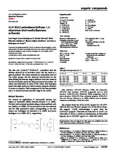
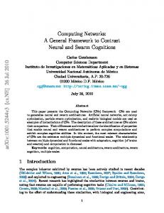
An example of one plane of multi-log
N network with N = 16.
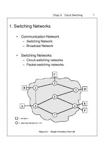
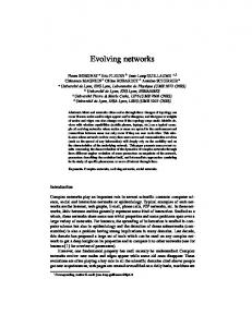
When two paths representing two connections intersect in at least one vertex of the bipartite graph, then one of these connections is blocked. This means that these connections should be set up through two different planes of a multiswitching and intersect in network. For instance connections vertex 0 of stage 2, so they cannot be set up in the same plane. . This Let us consider a path representing connection path contains node of stage 0, node of stage , and nodes . In nodes and path cannot in stages 1 trough intersects with any other path. In stage 1 the considered path may intersects with one path from one node in stage 0. In stage 2 this path may intersects with the additional paths from two nodes in stage 0. In general, the considered path may intersects , with additional paths in a node of stage , nodes in stage 0. Let be the set of these inlets from , where ) whose paths can (excluding inlet and all in a node of stage . Inlets belonging to intersect with path will be called accessible from stage . In the same way, set as the set of those outlets (excluding outlet we denote and all , where ) whose paths can intersect with path in a node of stage . Outlets belonging to set will be and also called accessible from stage . We have , where denotes the cardinality of set . in the graph of Fig. 2, For example, let us consider path . In this case , and and , . C. Multicast Connections
Fig. 2.
A graph representation of the switching network with
N = 16.
only the baseline architecture will be considered, however, results obtained are also true for other topologically equivalent switching networks. Inputs and outputs of a switching network from top to bottom, respectively, are numbered from left to and stages are respectively numbered . An example of 16 16 switching right, where network is shown in Fig. 1. B. Bipartite Graph Representation Throughout our discussion we will use bipartite graphs representation proposed in [3] and [5]. Such representation of the switching network of Fig. 1 is shown in Fig. 2. In the bipartite graph representation an edge (or link) corresponds to a switching element (crosspoint) and a vertex (or node) represents an inlet or an outlet of a 2-by-2 switching element. stages of nodes, This graph representation contains from left to right, respectively. The numbered nodes in stage 0 correspond to inputs of a switching network and the nodes in stage correspond to outputs of a switching from top network. These nodes are numbered to bottom, respectively. A connection from inlet to outlet will be denoted by . Such a connection is representing by the path from node in stage 0 to node in stage . Connections , and are examples of point-to-point connections. Paths representing these connections are shown in Fig. 2 in bold lines.
to outlets Let a connection from inlet be denoted by , where , . Thus is a point-to-point and it is a multicast connecconnection if and only if . For instance, connections , and tion for are point-to-point connections, while is a multicast connection. As it was already said, paths representing and intersect at a vertex of stage 2. connections intersects with one of Similarly the path of connection . paths belonging to the multicast connection In general, paths belonging to the given multicast connection can be set up using different strategies. In one of strategies all paths of the multicast connections have to be set up through the same plane. If such strategy is used, in the considered example is to be set up through one plane, and connecconnection —through another plane. In another strategy tion each path of a multicast connection can be set up independently of other paths of this connection. A multicast connection can be also set up using strategies based on the concept called blocking window [1], [17]. Control algorithms and blocking windows will be discussed in the next Section. III. A CONTROL ALGORITHM A. Blocking Windows A control algorithm used for setting up connections may result in a performance of a switching network (i.e., lower blocking probability) or, when a switching network is nonblocking for a control algorithm used, may reduce the hardware switching networks an complexity [13], [14]. In multi-
´ SKI AND DANILEWICZ: WSNB AND SSNB OPERATION OF MULTICASE MULTIKABACIN
Fig. 3.
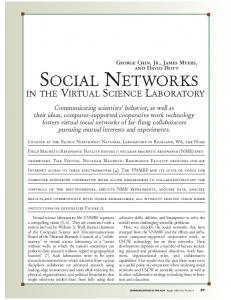
Examples of blocking windows in switching network with
N = 16.
algorithm based on a concept called blocking window may be used. A blocking window is defined as follows. be Definition 1: Let a set of outputs subsets divided into , where , and . Each subset is called blocking window. A blocking window was already used in [1], [17], but it was , where denotes the greatest integer limited to less than or equal to . In this paper we consider more gen, and we show, that the less eral case. We assume number of planes is sufficient for nonblocking operation for other values of . An example of blocking windows is shown and , the outin Fig. 3. For instance, when puts are divided into four blocking windows, each of which , , contains four outputs: , and . For there is only one blocking window containing all outputs of the switching network. An example of multicast connection is also shown in Fig. 3. For outputs 1 and 2 belong to the same blocking window and other outputs of this connection are in different blocking windows. B. A Path Searching Algorithm Blocking windows will be used in the control algobe a new rithm for setting up connections. Let can be divided into subconnection. The set of outputs such that each subset contains all possible sets belonging to the blocking window , outputs of set . Connections are called subconnections of connection . For considered earlier instance, connection , , can be divided into subconnections , and if or connections and if . Each of subonnections is switching to be set up through one plane of the multinetwork. The control algorithm is shown in Fig. 4. . Let us consider a switching network of Fig. 3, and let and (marked by In this network connections dashed lines) are already set up through plane 0. The new conwill be divided into subconnecnection
SWITCHING NETWORKS
1027
tions , , , and (Step 1). and check if it We choose the first subconnection and can be set up through plane 0. Since connections do not block the subconnection considered, it can be set up through this plane. The second subconnection cannot be set up through this plane since it is blocked by con. We have to choose the next plane for this subnection cannot be set up connection. Similarly, subconnection ), but it can be added to through plane 0 (connection in plane 1, since both belong to the same connection can be multicast connection. Finally, subconnection set up through plane 2. It should be noted that if a new connection is a point-to-point connection, then it has one subconnection. In the next parts of the paper, we will use also terms: maximum blocking configuration at stage and multicast connecbe a new connection. In stage tion at stage . Let this connection may be blocked by connections to . Simconnections to will block the conilarly, in stage , connecsidered connection. Finally, in stage will also block connection . In the worst tions to case these connections may be set up through different planes. Such a set of connections will be called a maximum blocking for output and will be denoted configuration at stage . Formal definition of is as by follows: : Definition 2: ; , ; ; and where denotes a set of nodes , . in connection path may occupy Such planes, and these planes will by inaccessible by connection . . Let us now consider a node at stage , accessible inputs. Outputs accessible This node has blocking windows. from this node may belong to up to , where and each element Connection of belongs to a different blocking window accessible from stage , may be set up through different planes. Such connection will be called multicast connection at stage and will be denoted . by is a connection , Definition 3: , , : , where , and for . in network is shown in An example of is also Fig. 5. shown in this figure. IV. WSNB CONDITIONS A. Nonblocking Conditions for In this Section the number of planes needed for a multicast switching network to be nonblocking multiwill be derived. We will assume that Algorithm 1 is used for setting up connections. We will consider several cases for , . different size of a blocking window will be considered in the Firstly the case with following theorem.
1028
IEEE TRANSACTIONS ON COMMUNICATIONS, VOL. 50, NO. 6, JUNE 2002
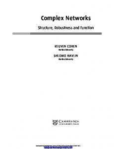
Fig. 4. Algorithm 1 for setting up connections.
Theorem 1: Consider a multinetwork created by vertically stacking copies of work together. Then the network is WSNB for provided that Algorithm 1 is used if and only if:
for
and
when
switching net-
is odd (1)
for
when
is even
is to be added in a Proof: Let a new connection switching network. It may be a point-to-point connection or a subconnection of a multicast connection. This connection is
blocked in one plane if another connection is already set up through one of nodes belonging to the path between input and output . In stage connection may be blocked , where , and . In by connections this connection may be blocked by connections stage , where , and . Finally, in stage this connection may be blocked by connections , , and . These connections constitute where and in the worst case they may be set up trough planes will be inaccessible by the condifferent planes. So , where nection
(2)
´ SKI AND DANILEWICZ: WSNB AND SSNB OPERATION OF MULTICASE MULTIKABACIN
SWITCHING NETWORKS
When also consider
or when
1029
and and
is odd we may
. However, since , then there is only one output free in blocking window accessible from nodes of all stages from 1 to , so we may have . In this case we have only one connection from
(4)
Fig. 5.
An example of
(0; 3) and
MMC (31;
s are point-to-point connecSince all subconnections of tions (this means that they occupy as little outputs in blocking window as possible), each of them is set up through different s occupy all possible outputs in planes, and those blocking windows accessible from considered stages then this is a worst case for . In the worst case sets of and planes are disjoint and one more plane is needed for setting up the new connection. and for and odd we have For
1; 4; 2).
We have now all outputs of the blocking window containing output occupied. Output is the desired output and connections to other outputs of the blocking window are set up through different planes. Since there is no free outputs in the blocking window and each connection to outputs in blocking window is set up through different plane, then there planes. So it is the is no possible to occupy more than inputs worst case for . On the other hand we have accessible from stage 1, and from this stage we can get to different blocking windows, but outputs belonging to outputs in one blocking window are already occupied. We can . Similarly, we can construct . In general we may construct for . These have connections will occupy outputs in one blocking window (accessible from nodes of ). Since each blocking window all stages from 1 to contains outputs, this means that there are still free outputs and even in this blocking window. However, for . It means that outputs of the set we have belong to the same blocking window as output and cannot be considered. In the worst case each subconnection of from input with connection may be set up through different planes, so
(3) planes may be occupied by these connections.
(5) (6) For
and
even, we have
(7) (8) Taking into account that for , we finally get
and
even we have
(9) Necessity can be proved by showing the set of events leading to occupancy of planes, where is given by (1). It should be noted that this set of events may be constructed in different way depending on and . We will show here the case when and is odd. Let us also assume that the new connection . to be set up is ———– , We have: , to do For set up connections
. Let , where
. .
1030
IEEE TRANSACTIONS ON COMMUNICATIONS, VOL. 50, NO. 6, JUNE 2002
These connections are set up through plane 0. Now in this can be set up. For other plane only subconnection subconnections of this multicast connection this plane is inaccessible. For
to do set up connections set up connection disconnect set up connection
;
This means that next , where nection
planes will be inaccessible to con-
(12) ———– So all together
; ;
(13)
.
It should be noted that connection for is in conflict with connection in plane 0. So it has to be set up in plane 1. All other connections will also be set up in plane 1. Now in this plane only can be set up. subconnection By analogy we may set up connections which will block in plane 2, and so forth. Finally, subconnection is set up through planes (for we have ), and all other connections are disconnected. In a current state of the switching network following set of events will cause that a path for a next connection will be firstly . checked in plane
planes are necessary for a switching network to be nonblocking. and odd we have: From (1), for (14) It should be noted that for
even and
we have: (15)
It is the same result as in [1]. It is not difficult to show, that the number of planes is growing when is getting smaller, so the minimum number of planes is . obtained for the biggest value of , i.e., for B. Nonblocking Conditions for
set up connection set up connection disconnect connection
in plane
Now let us assume that . Before we move to the nonblocking conditions in this case, let us give one more definition. be divided into Definition 4: Let a blocking window subsets
; ;
. , and let
In the similar way we have: and
. Each planes. We have:
of these connections will occupy
where
(10) From (4), since
is odd and
, we have: (11)
planes are inaccessible by connection All set of events causes that every time connection set up through the next plane: to do For to do For ; set up connection set up connection disconnect connection set up connection disconnect connection
. Following has to be
;
Each subset is called a subblocking window. switching Theorem 2: Consider a multinetnetwork created by vertically stacking copies of work together. Then the network is WSNB for provided that Algorithm 1 is used if and only if: (16) Proof: Similarly as in Theorem 1 the proof will be based on constructing the worst state of a switching network. Let a is to be set up, where belongs to one new connection . In this case a blocking blocking window, and let s. window contains , and . We may construct Even : Let which will occupy
; ; .
(17)
´ SKI AND DANILEWICZ: WSNB AND SSNB OPERATION OF MULTICASE MULTIKABACIN
planes, and all outputs in are busy. Since for even we , than all inputs accessible from have are also busy and cannot be considered in next stage may occupy connections. Connections to outlets of planes, where
SWITCHING NETWORKS
s. So
s in stage
numbered from
to
1031
will occupy outputs in next s. These s are . In this way next
(20)
(18) and , than these planes will be inacWhen . In we have still free outputs. cessible by we have In stages numbered from 1 to accessible inputs. It means that there will be posfor all accessible sible to set up in each of these stages all outputs in the blocking window are alinputs. When next may be considered. ready assigned. For and occupy inConnections in , so we have still inputs free. puts of : and We may construct two , , and these connections will use
. This time planes will be inaccessible by a connection planes, occupy outputs in connections in to . subblocking windows from s which can be occupied Finally, in stage number of s is , however, in this case we have only by s with free outputs. So, the s in stage will occupy
(21) planes, and all outputs in the blocking window are assigned exoutputs in . Connections in planes occept to . The cupy subblocking windows from was calculated is shown in Fig. 6. way we may now construct In stages numbered from 1 to s for each input and, by analogy to Theorem 1, these connections may occupy (22) In the worst case these sets are disjoint and one more plane is , so in general we can write: needed for connection
(19) in means that connections in planes Index , . occupy outputs in are now used and we have still free All outputs in . So we may consider the next in stage outputs in . , , is considered. In this section, Let stage and . Connecwe have s of previous stages will occupy inputs tions in so we have still accessible from stage free inputs. These inputs may be used for constructing s in stage . We may construct
It should be however noticed, that for (i.e., s so we have in this case we have only two
(23) For
such in
),
we have
s. Each
. In one
in stage will occupy outputs and one output we may construct (24)
1032
IEEE TRANSACTIONS ON COMMUNICATIONS, VOL. 50, NO. 6, JUNE 2002
(a)
(b)
(c)
(d)
(e) Fig. 6. Number of planes in the proof of Theorem 2, n even, (a) p , (b) p , (c) p , (d) p
For
we can write
, (e) p
.
(25) we obtain It should be noticed, that if in (25) we put than (25) becomes (23). Taking also into (24) and if and is even we have account that
It should be also pointed out, that for , and but formula (16) is true in this case. For odd construction of the worst case scenario is similar s to that for even. However, in this case, outputs in two
´ SKI AND DANILEWICZ: WSNB AND SSNB OPERATION OF MULTICASE MULTIKABACIN
SWITCHING NETWORKS
will be occupied by two s, so planes a can be inaccessible for a new connection. For s and all outputs in blocking window is composed of two this blocking window are occupied. This means that we cannot s to all blocking windows available from the node set up . So is given by in stage ,
TABLE I SET OF EVENTS IN 32 32 SWITCHING NETWORK
1033
2
(26) outputs in the third may be occupied For and by connections constructing . connections to outputs accessible from stage This connections will occupy
Also for odd we have . The total number of planes is in this case also given by (16). Necessity can be proved by showing the set of events leading to occupancy of planes, where is given by (16). Let us as, is to be set up. Similarly as sume that connection . in Theorem 1 in stage 1 we may construct s can be constructed in next stages Also by analogy next . This connections will occupy planes, up to stage is given by (26). Also by analogy to the last part of where the set of events for Theorem 1 we may construct connection planes, where is given by (17). Now which will occupy , every time connection is to be set up, it has to be set up through the next plane. So we planes will be inaccessible by connecmay cause that next . The next connection , tion will have to be set up through the next plane, and so forth. Finally, in this way conwill be blocked in already occupied planes and nection one more plane is needed. In Theorems 1 and 2 we have proved nonblocking conditions for different . Now the question is for which the number of planes is minimized. C. Minimum Number of Planes reaches minimum The number of planes for and it is given by (15) for even, and by (14) for for odd. For the number of planes is given by we have (16). If is even and
(27)
By checking for we can conclude, that for less number of planes is needed for than for . For we have and . For odd we have
and
It can be checked, that for , and for we have always . For instance when we have and . V. NUMERICAL EXAMPLES We will give now an example showing that the number of planes given in Theorem 1 is necessary. Let us assume that and in this case, for we have . The set of events leading to the occupancy of 9 planes is given in Table I. Connections marked by asterisk are connections which still exist when the new connection is to be set up and it must use plane 8, since other planes are inaccessible for this connection. switching network An example of the worst state in is shown in Fig. 7. This is a case given by Theorem 2. for outputs and each of Each blocking window contains outputs. Let us assume subblocking windows has that the considered connection is the multicast connection . There is possible to set up and . Each of two s may occupies up to different . Connections which planes. So, we have are connections , , constitute , , , and . All of
1034
Fig. 7.
IEEE TRANSACTIONS ON COMMUNICATIONS, VOL. 50, NO. 6, JUNE 2002
An example of the worst state for Theorem 2.
them are marked in Fig. 7. Similarly, we construct . Two subblocking windows are still free in the first blocking window. Now, we have no accessible inputs in the nodes of ), but the fourth stage ( in the third stage we have four free inputs. It is possible to set and four connections from inputs accessible up ). This connections may from the stage 3 ( planes. Outputs in the fourth occupy next and subblocking window may be occupied by two connections from inputs accessible from the stage 2 ). In the worst case these connections will occupy ( planes. In the fourth subblocking next window two outputs are still free, but in the first stage one may input is accessible and from this input be set up. This multicast connection may be set up by different planes (according to Algorithm 1). Thus, next planes may be used. This multicast connection is in Fig. 7. Finally it is
Theorem 3: Consider a multiswitching netnetwork created by vertically stacking copies of work together. Then the network is SSNB if and only if: (28) Proof [Proof of Sufficiency]: Let us consider a connecting path between input and output . In a node of stage this connecting path may intersect with connecting paths to outputs . In the worst case each of these paths may be belonging to set up through different planes. This means that no more than (29)
planes will be inaccessible by a connection plane is needed to set up this connection. So
, and one more
(30)
VI. SSNB CONDITIONS Up till now we assumed that Algorithm 1 is used for path searching. In other words WSNB networks were considered. In SSNB networks a new connection can be set up regardless path searching algorithm used. In this section conditions for switching strict-sense nonblocking operation of multinetworks are considered.
Necessity can be proved by showing the set of events leading . Let us assume that a to the blocking state, when planes. We switching network is composed of will look for a plane for a new connection starting from the plane through which last connection was set up. Following planes (an set of events leads to the occupancy of event means setting up of a new connection or disconnecting one of existing connections). We also assume that multicast ). connection is to be set up through one plane (
´ SKI AND DANILEWICZ: WSNB AND SSNB OPERATION OF MULTICASE MULTIKABACIN
SWITCHING NETWORKS
1035
TABLE II NUMBER OF PLANES IN MULTI-log NETWORKS FOR DIFFERENT n
N
Fig. 8.
An example of Theorem 3.
———– (plane 0). Set up connection to do For set up connection set up connection disconnect connection to do For set up connection ); set up connection disconnect connection set up connection disconnect connection ———–
(plane
(plane ); .
);
(plane (plane
); ;
(plane .
);
planes occupied and mulWe have now cannot be set up ticast connection through any of these planes. So one more plane is needed to set up this connection. The set of events leading to the occupancy of 4 planes in the SSNB switching network is as follows: ———– (plane 0), (plane 1), and Set up connections (plane 1). . Disconnect connection (plane 2), and (plane Set up connections 2). . Disconnect connection (plane 2). Set up connection . Disconnect connection (plane 3). Set up connection ———– SSNB switching netAn example of the state of the work after above operations is shown in Fig. 8. VII. COMPARISON AND CONCLUSIONS The number of planes in different multinetworks are gathered in Table II. It can be seen that the multicast networks require more planes than the network with point-to-point connections. For the number of planes is less than that for when is odd. Column shows the minimum number contains for which is obtained. of planes and
For
the minimum number of planes is obtained for and for —for if
is even. networks were In this paper WSNB and SSNB multiconsidered. We have derived the general formula for WSNB operation of switching networks for different sizes of a blocking window provided that Algorithm 1 is used. We have also shown, that the minimum number of planes can be reached for different sizes of blocking window depending is odd or even, outputs. not necessary when blocking window contains The WSNB conditions with the minimum number of planes has not been determined yet. We have also proved that considered switching networks are SSNB when they consists of at least planes. REFERENCES [1] Y. Tscha and K. H. Lee, “Yet another result on multi-log N networks,” IEEE Trans. Commun., vol. 47, pp. 1425–1431, Sept. 1999. [2] V. E. Bene˘s, Mathematical Theory of Connecting Networks and Telephone Traffic. New York: Academic, 1965. [3] C.-T. Lea, “Multi-log N networks and their applications in high-speed electronic and photonic switching systems,” IEEE Trans. Commun., vol. 38, pp. 1740–1749, Oct. 1990. [4] C.-T. Lea and D.-J. Shyy, “Log (N; m; p) strictly nonblocking networks,” IEEE Trans. Commun., vol. 39, pp. 1502–1510, Oct. 1991. [5] , “Tradeoff of horizontal decomposition versus vertical stacking in rearrangeable nonblocking networks,” IEEE Trans. Commun., vol. 39, pp. 899–904, June 1991. [6] C.-T. Lea, “Multirate log (N; e; p) networks,” in Proc. GLOBECOM, 1994, pp. 319–323. [7] , “Buffered and unbuffered: A case study based on log (N; e; p) networks,” IEEE Trans. Commun., vol. 44, pp. 105–113, Jan. 1996. ˙ “Non-blocking operation of multi-log N [8] W. Kabacin´ski and M. Zal, switching networks,” in Third IEEE Int. Workshop on Broadband Switching Systems, Kingston, ON, Canada, 1999, pp. 140–144. [9] M. Listani and A. Roveri, “Switching structures for ATM,” Computer Commun., vol. 12, pp. 349–358, Dec. 1989. [10] T. T. Lee, “Nonblocking copy networks for multicast packet switching,” IEEE J. Select. Areas Commun., vol. 6, pp. 1455–1467, Dec. 1988.
1036
IEEE TRANSACTIONS ON COMMUNICATIONS, VOL. 50, NO. 6, JUNE 2002
[11] J. Y. Hui, Switching and Traffic Theory for Integrated Broadband Networks. Boston, MA: Kluwer, 1990. [12] C. Clos, “A study of nonblocking switching networks,” Bell Syst. Tech. J., pp. 406–424, 1953. [13] F. K. Hwang and A. Jajszczyk, “On nonblocking multiconnection networks,” IEEE Trans. Commun., vol. COM-34, pp. 1038–1041, Oct. 1986. [14] Y. Yang and M. Masson, “Non-blocking broadcast switching networks,” IEEE Trans. Computers, vol. 40, pp. 1005–1015, Sept. 1991. [15] Y. Yang and J. Wang, “On blocking probability of multicast networks,” IEEE Trans. Commun., vol. 46, pp. 957–968, July 1998. [16] M. Stasiak, P. Zwierzykowski, and M. G˛labowski, “Blocking probability in the multi-service switching networks with multicast traffic,” in 10th IEEE Mediterranean Electrotechnical Conf.—MELECON, vol. 2, (Cypr), 2000, pp. 868–871. [17] Y. Tscha and K. H. Lee, “Non-blocking conditions for multi-log multiconnection networks,” in Proc. GLOBECOM, 1992, pp. 1600–1604.
N
Wojciech Kabacin´ski (A’94–SM’01) received the M.Sc., Ph.D., and D.Sc. degrees in communication from Poznan´ University of Technology, Poland, in 1983, 1988, and 1999, respectively. Since 1983, he has been working in the Institute of Electronics and Telecommunications, Poznan´ University of Technology, where he currently is an Associate Professor. His scientific interests cover broad-band switching networks and photonic switching. He has published three books, 78 papers, and holds 10 patents. Prof. Kabacin´ski is a member of the IEEE Communications Society and the Association of Polish Electrical Engineers.
Grzegorz Danilewicz was born in Poznan´, Poland, on March 15, 1968. He received the M.Sc. and Ph.D. degrees in telecommunications from the Poznan´ University of Technology, Poland, in 1993 and 2001, respectively. Since 1993, he has been working in the Institute of Electronics, Poznan´ University of Technology, where he currently is an Assistant Professor. His scientific interests cover photonic broad-band switching systems with special regard to the realization of multicast connections in such systems. He has published 24 papers.