Most real time implementations of SLAM are based on Kalman Filters extended ... One of the biggest challenges in robotics is navigation in large unstructured ...
1
Navigation and Mapping in Large Unstructured Environments Jose Guivant, Juan Nieto, Favio Masson and Eduardo Nebot Abstract This paper addresses the problem of autonomous navigation in very large unstructured environments. A new Hybrid Metric Map (HYMM) structure is presented that combines feature maps with other metric representation in a consistent manner. The global feature map is partitioned into a set of connected Local Triangular Regions (LTRs), which provided a reference for a detailed multi-dimensional description of the environment. The HYMM framework permits the combination of efficient feature-based SLAM algorithms for localisation with, for example, occupancy grid maps for tasks such as obstacle avoidance, path planning or data association. This fusion of feature and grid maps has several complementary properties; for example, grid maps can assist data association and can facilitate the extraction and incorporation of new landmarks as they become identified from multiple vantage points. This paper also presents a path planning technique that efficiently maintains the estimated cost of traversing each LTR. The consistency of the SLAM algorithm is investigated with the introduction of exploration techniques to guarantee a certain measure of performance for the estimation process. Experimental results in outdoor environments are presented to demonstrate the performance of the algorithms proposed.
I. Introduction The last few years have seen the implementation of autonomous systems in industrial applications that operate in a reliable and consistent manner in areas such as stevedoring [1], mining [2] and agriculture [3]. These systems make use of absolute information such as GPS or maps of the environment to solve the localisation problem. More complex applications have been presented solving the localisation and mapping problem simultaneously. This problem is usually referred to as Simultaneous Localisation and Mapping (SLAM) [4] or Concurrent Mapping and Localisation (CML) [5]. Most real time implementations of SLAM are based on Kalman Filters extended with appropriate models for the vehicle and sensors to solve the SLAM problem [4]. In [6] the real time implementation aspects of SLAM using EKF techniques were addressed. A Compressed Extended Kalman Filter (CEKF) algorithm was introduced that significantly reduces the computational requirement without introducing any penalties in the accuracy of the results. Sub-optimal approaches were also presented in [7][8] to update the full covariance matrix of the states bounding the computational cost and memory requirements. There are also other approaches that make use of a combination of particle filters and Kalman filters to represent the pose of the vehicle and location of the landmarks respectively [9]. In this case the map building and localisation processes are decoupled by assuming that the pose of the vehicle is known. This is achieved with a sufficient number of particles to represent the distribution of the true pose of the vehicle at all times. One of the biggest challenges in robotics is navigation in large unstructured environments. In particular, high integrity autonomous navigation presents a large number of unsolved problems in the area of perception, localisation, mapping and control [10]. SLAM algorithms are based on exploration and revisiting stages to maintain consistent global maps. Depending on the quality of the kinematics models and external sensors, the exploration stage can be extended to larger areas. Nevertheless no matter how good sensors and models are, at one point the accumulated errors will make the SLAM process prone to catastrophic faults due to failures of the data association process or due to strong non-linearities present when working with large uncertainties. We consider that the key areas that need to be addressed to achieve high integrity autonomous systems are: • Map Representation: One of the most important challenges when working with very large environments is map representation. Map representation is the process of constructing an internal representation of the world from real-time sensory information. An optimal representation of the environments in unstructured dynamic worlds is one of the outstanding and significant research challenges in building intelligent systems. • Consistency: A second important problem is related to the consistency of the robot localisation and map building process. In general large environments can be prone to large uncertainties in estimates making linearisations not appropriate for standard filtering processes. In this case the filter will usually generate over-confident non-consistent results. • Data Association: In every estimation problem, the measurements need to be associated with the underlying states that are being observed. This is usually referred to as the data association process and is one of the most difficult problems in localisation or SLAM applications. Successful data association involves association of the correct measurement with the correct state and initialising new tracks and detecting and rejecting spurious measurements [11] . There are different ways to implement the data association process [12]. The most widely used algorithm for data association is the Nearest Neighbour (NN) where each observation is tested against each hypothesis. When multiple observations are jointly processed a more robust data association can be obtained. This joint data association intrinsically considers the geometric relationship between a set of landmarks [13–15]. This paper will address these three fundamental navigation issues. It presents a new Hybrid Metric Map (HYMM) representation that combines feature maps with any other metric representation. In particular it includes a combination
2
of features / occupancy grid approaches to achieve efficient global localisation with features and allows detailed navigation in local areas by making use of OG maps. In this paper detailed navigation refers to the capabilities of an autonomous system to perform tasks such as path planning, obstacle avoidance, etc. The aspect of consistency is also addressed presenting new efficient algorithms to evaluate the information available in different regions of the map. This will make possible to design and plan trajectories to maintain a robot with a position uncertainty bounded, avoiding therefore inconsistent estimates. Finally the data association problem is addressed with a hybrid architecture that combines CEKF with Particle Filter methods. The paper is organised as follows; Section II presents a brief summary of different map representations. Section III introduces the Hybrid Metric Map (HYMM) representation. Section IV addresses the aspect of map consistency presenting new measures of information and efficient algorithms for real time implementation. The aspect of data association in a complex environment is presented in Section V. Finally Section VI presents experimental results in outdoor environments and conclusions are given in Section VII. II. Autonomous Mapping Autonomous mapping is the process responsible for obtaining an internal representation of the environment from external information. The mobile robot uses a wide variety of sensors to obtain information about the environment. However, the sensors are not perfect and the information provided is usually perturbed by some type of noise. One of the key problems in mapping is to model and incorporate this uncertainty into the map. Many autonomous applications can only rely on observations of the world taken relative to the pose of the rover. The error in the robot pose estimation will introduce another source of uncertainty. Probabilistic techniques have been widely used in mapping problems since they can incorporate and propagate sensor and vehicle model errors into the rest of the system. The next subsections present a brief review of the most common mapping techniques used in localisation and SLAM: occupancy grids, feature based maps and topological maps. A. Occupancy Grid Maps The occupancy grid mapping technique (OG) represents the environment with a grid of fixed resolution. The OG is a multidimensional grid that maintains stochastic estimates of the occupancy state of each cell. The OG maps were introduced by Elfes and Moravec [16, 17] and have been widely used due to the simplicity of their implementation. Each cell stores the probability of being occupied or free. The state variable S(Ci ) associated with the cell Ci is defined as a binary random variable where P rob(Ci = OCC) + P rob(Ci = F REE) = 1 since the cell states are exclusive. The evaluation of the posterior over the occupancy of each grid cell (1) is based on binary Bayes filters: P rob(Ci = OCC|xk , Z k ) ∝ P rob(zk |Ci = OCC)P rob(Ci = OCC|Z k−1 )
(1)
In practise the update is usually solved using Odds formulation [17]. One of the main problems with OG maps is that they do not take into account the correlation between cells that exists due to the robot pose uncertainty. This technique assumes that the states’ variables of each cell are independent, an assumption that is not true specially when working in large areas where the robot pose can potentially accumulate significant errors. OG have been used mainly for localisation given a priori map or for map building given the robot pose. More recently some SLAM formulations using OG have started to appear [18]. However, as stated in [19] it is of fundamental importance to have a representation of the robot pose and sensor uncertainty and their correlation to achieve convergence of the SLAM process. This is not possible using OG techniques. One obvious case where OG based SLAM fails is when attempting to close a large loop. In this case the actual pose of the robot will usually have a considerable error. Even in the case where it is possible to associate the observations correctly with the global map to correct the error in the local map, it will not be possible to propagate the corrections back through the rest of the map. This is due to the fact that OG approaches represent the uncertainty in a local frame, but do not take into account the correlation between the local and the global frames. This will result in an inconsistent global map. In general OG techniques provide very rich representations of the environment, which will enable the robot to perform tasks such as path planning and reactive navigation in local areas but they cannot provide consistent global map estimates when working in large environments. B. Feature Maps Feature map techniques [20] represent the environment with parametric features such as points, lines, cylinders, corners, etc. A feature is a distinctive part of the environment that can be easily discriminated by a type of sensor and described with a set of parameters. This method requires a model for each type of feature considered in the environment. A comprehensive description of the SLAM problem using features was presented in a seminal paper in [21]. Although only the location of the features is used to represent and maintain the map, other information such as geometry, color, etc., can also be used in the identification stage or during the data association process. Real time implementations of SLAM have been mostly based on the use of Extended Kalman Filters (EKF) [6, 22]. With this approach the state
3
250
200
North(meters)
150
100
50
0
−50
−100 −150
−100
−50
0 East(meters)
50
100
150
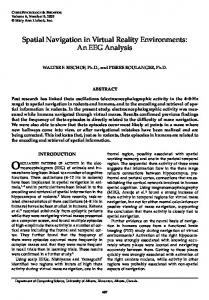
Fig. 1. Estimated path and features map obtained in Victoria Park.
vector containing the robot pose is augmented when new features are observed and validated. Since the features are observed with respect to the robot position the estimated robot pose and map will be correlated due to the robot pose uncertainty. At the limit, when many observations are incorporated, the map becomes fully correlated. This means that a theoretically perfect map can be achieved if the absolute location and orientation of a feature is given. Figure 1 shows a typical result of an estimated map and trajectory obtained using feature based SLAM in an outdoor environment. In this experiment the most common relevant features were trees. The profile of the trees was extracted from a laser sensor, and the most likely trunk centres were estimated. A Kalman filter was implemented to reduce errors due to the different profiles obtained when observing the trunk of the trees from different locations. These methods can also be augmented with absolute information as presented in [6]. More detailed information on the experiment and the complete experimental dataset is available in [23]. Feature maps are suitable in applications where it is possible to distinguish geometric features from the environment. This characteristic makes feature map techniques not useful in highly unstructured environments where it is not always possible to find clearly distinct geometries. Moreover, the map obtained could be a sparse representation of the environment, which in most cases will be of limited resolution and will not be able to provide information to perform detailed navigation. C. Topological Maps Topological approaches [24] represent the robot environment by using graphs. With metric approaches such as feature maps or occupancy grids, the objects’ locations are defined in a cartesian coordinates frame. With topological maps the environment is represented by nodes and arcs that correspond to possible travel paths. Each node represents a distinctive place in the environment, and the edges represent the relative position between adjacent nodes. With pure topological maps it is only necessary to represent the connectivity between nodes and no information about the absolute position of the nodes is required. Figure 2 shows an example of a topological map. Topological maps are attractive for the compactness of the representation. They are efficient representations for tasks like path planning and are appealing in indoor applications where clear distinctive places can be found between areas where navigation can be performed aided by very basic information such as wall following. One of the main problems with this representation in more complex environments is place recognition. If the robot travels between two places that look alike, the lack of metric information makes the discrimination of these two places very unreliable. In this case the logic of the topological map will be broken and the robot will not be able to evaluate its position. This is probably the main reason why most of the approaches use metric information over topological maps in large unstructured environments [14, 24]. Finally another limitation of this technique is that it does force the planner to follow specific trajectories to pass through or very near distinctive places.
4
100
80
60
40
20
0
−20
−40
−60
−80
−100 −100
−80
−60
−40
−20
0
20
40
60
80
100
Fig. 2. Typical topological map, the ‘*’ are the distinctive places and ‘-’ the path between the distinctive places.
D. Hybrid Maps In the past few years various studies presented implementations of maps combining different approaches [25]. These studies range from integrating topological with metric maps [14, 26–28] to the use of multi-resolution OG approaches [18]. In [14] and [28], the authors introduce a hybrid approach that uses topological and feature maps to perform large-scale SLAM. This method scales very well to large environments using feature maps only. In [18] a localisation procedure using correlation techniques to register real time local OG maps with the existing global map is presented. Extensions to SLAM are also presented incorporating new features with a method based on sequential localisation and posterior map building. Unfortunately this method generates inconsistent results when operating in large areas since it has already been proved that these two tasks have to be performed simultaneously to guarantee consistency in the results. The next section presents a new mapping framework called Hybrid Metric Maps (HYMM), that combines feature maps with other metric representation in a consistent manner. III. Hybrid Metric Maps (HYMM) Overview The HYMM approach combines feature maps with other metric representation. This approach allows the robot to obtain a very rich and accurate representation of the environment and at the same time localise itself (SLAM). Having a rich representation of the environment will enable the robot to perform precise path control and more demanding tasks such as obstacle avoidance. Moreover the HYMM representation presents significant advantages to solve the data association problem in a very robust manner using for example, point data correlation techniques [29]. When working with feature based maps, a set of features can be used to partition the region covered by the map. These partitions are shown in Figure 3 and consist of a set of connected local triangular regions (LTRs). Each LTR is defined by the position of three landmarks called vertex as shown in Figure 4. Any point that belongs to a LTR can be defined by a convex linear combination of the three vertex points associated with this sub-region. In Figure 4 a LTR Ωi is defined by the vertex points {Li,1 , Li,2 , Li,3 }. A local coordinate frame is defined based on the three vertex points according to Equation (2). − → ai = Li,2 − Li,1 = (ax , ay ) → − bi = Li,3 − Li,1 = (bx , by )
(2)
Any point that belongs to Ωi can be expressed as: → − → ai + β · bi = X = Li,1 + α · − = (1 − α − β) · Li,1 + α · Li,2 + β · Li,3 α > 0, β > 0 α+ β ≤1 ∀ X \ X ∈ Ωi
(3)
5
80
60
40
20
0
−20
−40
−60
−80
−100 −80
−60
−40
−20
0
20
40
60
80
Fig. 3. Landmarks map (‘*’) and a particular partition on triangular sub-regions (LTRs). As can be seen, not all the landmarks are needed as vertex points in the LTRs definition. L2 L3
a b
L1
Fig. 4. Detail of an individual LTR defined by three vertex points, {Li,1 , Li,2 , Li,3 } and the direction vectors, {ai , bi }.
Furthermore any generic function z of the global position X can be locally defined as a function of the local representation of X. → − → (4) ai + β · bi ) = g(α, β) z = f (X) = f (Li,1 + α · − In some applications a function can be defined locally by an observer that has its position well defined with respect to the vertices of the related LTR. This means that the position uncertainty of the observer will be low since it is expressed with respect to a local frame. Then any information gathered from this location and associated with position can be accurately represented in the local frame. Due to the structure of the map, the vertex points and any interior point of the LTR are highly correlated. Then high uncertainty in the vertex points will not affect the quality of any property defined as a function of the observer position (local). This is true if the observer measures certain property z of points that are inside the LTR and is well localised with respect to the vertex points of this LTR. The property z is expressed as a function g(α, β), where (α, β) are the local coordinates. Any improvement in the estimation of the position of the vertex points will imply an improvement of z expressed in a global coordinate frame. If the position of the vertex points is exact (in respect to the global frame) then a linear coordinate transformation will provide the conversion from the local representation g(α, β) to the global frame version f (X). A typical application of this concept is when a robot is concurrently doing SLAM and measuring a property z. The property z does not necessarily have to be used for the robot localisation process. Assume a vehicle simultaneously doing SLAM and measuring three properties: soil salinity, humidity and terrain occupancy. These properties can be locally represented in each LTR using occupancy grid techniques. Figure 5 illustrates one example of different internal properties in a given LTR. In some cases, due to the high correlation between the vertex points and the vehicle pose states, it will be possible to represent a particular property as a deterministic function of the local coordinates (α, β) inside the LTR. In addition one of the properties (e.g. terrain occupancy) could be used for example to assist the data association stage of the SLAM process. If a set of observed objects are geographically close from the vehicle viewpoint, then the error due to the vehicle
6
7 6 5 4 3 2 1 0 1 1.5 2 2.5 3
1.3
1.2
1.5
1.4
1.6
1.7
1.9
1.8
2
2.1
2.2
Fig. 5. A set of properties can be defined as a function of the local coordinate variables. The triangular LTR’s shape can be seen on the plane xy (dashed lines).
(a)
(b)
5
3.5
4
3
3 2.5
2 2
1 1.5
0 1 −1 −1
Fig. 6. curve.
0
1
2
3
4
5
0.5
1
1.5
2
2.5
3
3.5
4
4.5
Effect of moving the base landmarks position. (a) Over a grid. ‘*’ before the update and ‘square’ grid after the update (b) In a
pose uncertainty will be a common component of these estimated landmark positions. This occurs in SLAM where the vehicle accumulates uncertainty in its estimated position and incorporates observations that are used to synthesise a map. Due to this fact the estimates of landmarks that are geographically close will present similar uncertainties and high cross-correlations. Any update in a particular landmark will imply a similar update on any landmark sufficiently close to the first one. The local representation defined in (3) takes advantages of this particular fact. It can be seen that X → Li,1 ⇒ α → 0, β → 0, (1 − α − β) → 1 X → Li,2 ⇒ α → 1, β → 0, (1 − α − β) → 0 X → Li,3 ⇒ α → 0, β → 1, (1 − α − β) → 0
(5)
This means that if a relative estimated point X, is close to Li,1 and the estimation process generates changes in the base landmarks Li,2 , Li,3 but no change is introduced in Li,1 then a very small change will be made over the estimate of X. This can be seen by analysing the variation of an internal point X when there is a change in the LTR landmarks position. δX = (1 − α − β) · δLi,1 + α · δLi,2 + β · δLi,3 = α · δLi,2 + β · δLi,3
(6)
From (6) it can be seen that δX → 0 when delta δLi,1 = 0 and α = β = 0. Figure 6 shows the effects of changing the position of the base landmarks in a LTR. In (a) the concept is illustrated in a grid, and in (b) in a curve. It is evident from Figure 6 that there will be small changes in the points close to the landmarks that have a small update, and large changes in the points close to the landmarks that have a significant update. The next subsections present some of the most important points of the HYMM approach.
7
4 3.5 3 1.5 2.5 1 2 0.5
1.5 1
0 0
0.5
1
0.5 1.5
2
2.5
3
3.5
0 4
Fig. 7. 2D LTRs definition based on 3D landmarks. The LTRs define a continuous piece-wise linear 2D surface in the 3D space. A more detailed and precise description can be obtained for each LTR by using its local 2D coordinate frame.
A. 3D Extension The HYMM can also be applied to represent 3D maps. The 2D triangular LTRs can be extended to 3D tetrahedral LTRs including an additional vertex point. The vectors to define the local frame are now three: → − ai = Li,2 − Li,1 − → bi = Li,3 − Li,1 → − c =L −L i
i,4
(7)
i,1
and any point that belongs to Ωi can be expressed as: → − → → ai + β · bi + γ · − ci X = Li,1 + α · − α > 0, β > 0, γ > 0 α+ β+γ ≤1
(8)
∀ X \ X ∈ Ωi Another useful representation can be obtained based on 2D LTRs and defining the vertex points in a 3D space. As shown in Figure 7 the LTRs can have different inclinations and are not necessarily horizontal or contained in the same flat surface. This representation allows, for example, the use of a piece-wise linear frame for terrain surfaces based on features. Over the defined LTRs a more detailed local description can be obtained as a function of the local coordinate variables (α, β). For example a function representing the level of the terrain surface in respect to the triangular flat LTR (perpendicular to it) can give useful information about the terrain traversability of certain area. B. HYMM using Occupancy Grids As mentioned before, the occupancy grid technique requires accurate determination of the robot’s pose. However, in real applications the robot’s pose is always known with some uncertainty. Previous hybrid maps using OG neglected this uncertainty and therefore they generate inconsistent results when applied to large environments. The approach presented here uses the features included in the stochastic map to define the triangular boundaries of a grid map. By using a feature based representation it is possible to estimate the vehicle position simultaneously with the map, however the map obtained is a sparse representation of the environment. Augmenting the map with the OG representation provides additional information to perform detailed navigation while at the same time obtaining a consistent and rich representation of the environment.
8
(a)
(b)
2.2
2.1
2
1.9 2.2 2.1
1.8
2
1.7 1.9 1.8
1.6 40
1.7
1.5 1.6 20
1.5
1.4
1.4
0
1.3
1
1.2
1
1.2
1.4
1.6
1.8
2
2.2
2.4
2.6
2.8
3
1.2
1.4
1.3 1.6
1.8
2
2.2
2.4
2.6
2.8
1.2 3
Fig. 8. A relevant property is the occupancy description in the LTRs. The doors of a particular LTR can be defined by the clear (empty) segments on its borders.(a) 2D plot, (b) 3D plot.
The HYMM representation can combine feature based maps with other local metric representation, in particular with OG maps. The approach uses the best of both worlds, the consistency of the feature maps, that will enable the robot to localise itself and the rich representation that is only possible with OG maps to perform detailed navigation. C. High Level Features In many situations an object cannot be initialised using the measurements taken from only one vantage point. This can be due to a variety of reasons: occlusion between objects, the size of the object in relation to the sensor field of view, an inappropriate feature model or just because the nature of the sensor makes the estimation of the feature location from only one location impossible (e.g wide-beam sonar) [30, 31]. Estimating partially observable features has been an important research topic in computer vision using stereo vision and bearing only information, where the initialisation of the features position is a significant problem. The problem of partially observable features has also been studied for localisation and SLAM applications. In [30] an approach is presented that delays the decision to incorporate the observations as map features. Consistent estimation is achieved by adding the past vehicle positions to the state vector and combining the observations from multiple points of view until there is enough information to validate a feature. In [31] intersection of range of constant depth of ultrasonic sensors is used to determine the location of features from multiple vantage points. Having a comprehensive representation of the environment will enable a delayed-processing to determine whether part of the map can qualify as a feature. Using the HYMM approach, in particular combining features and OG, will enable post-processing capabilities to continuously detect High Level Features in the OG maps. The newly detected features can then be added to the features map. This approach has the potential of incorporating a large number of feature models, some of them to be applied on-line at the time the observations are taken and the rest to run in background with the OG when computer resources become available. The landmarks can then be incorporated in a consistent manner into the features map. D. Submaps Compression Computational storage can become an important problem in mapping when working in very large and dense environments. This is also true even with feature based maps. The HYMM approach will also be prone to memory problems in large environments. However, a compression technique can be applied to reduce the amount of memory required. When the robot is travelling, only the active regions are needed and the rest can be compressed. The active regions can be defined as the regions that are visible to the robot sensors and the neighbourhood. For example, in the case of the HYMM implemented with a combination of features and OG, the compression can be done saving only the cells with occupancy probability bigger than a given threshold. All the other cells could be approximated as free space. A further simplification is by using a more efficient OG representation such as Quadtrees or Oct-trees [32]. E. Path Planning using LTRs’ partition Due to the nature of the representation a high accurate map can be obtained inside a LTR independently of its absolute location. If a set of properties, useful for navigation and path planning purposes, are locally described in each LTR then the set of LTRs that define the whole map will have all the necessary information required to deploy a global path planning strategy. The properties describing the occupancy in each LTR are essential for path planning purposes. An example of a list of properties can be: 1. Occupancy. 2. Probability of presence of humans, animals or other moving objects (traffic density). It can be a function of the time/date, weather, etc. 3. Terrain surface type (concrete, soil, sand, water).
9
4. Terrain surface shape. Each LTR defines a set of doors that link the LTR with its exterior. The doors are on the borders of each LTR, as in Figure 8 and indexed in a list of doors for the LTRs, e.g. Ωi : {Di,1 , Di,2 , ....., Di,ni }. A function describing the cost of moving from one door to another can be defined based on local properties (e.g. properties 1,2,3,4 above). Then a square matrix representing the cost of moving between doors can be defined. Ci ∈ Rni ·ni
γ1
� Ci (j, k) = minξ ( ξ µ(α, β) · |dlX |) ξ \ ∃ γ1 , γ2 , ∈ ξ , γ2 ∈ ξ , γ1 ∈ Di,j , γ2 ∈ Di,k , ξ ⊆ Ωi
(9)
where Ci (j, k) represents the minimum cost to go from door Di,j to door Di,k . The costs are calculated as line integrals of the cost function µ(α, β) along any possible (local) curve ξ that connects the couple of doors Di,j and Di,k . The cost function µ(α, β) is a combination of the individual cost functions where each individual cost function µs (α, β) focuses on a property as in 1, 2, 3, 4: µ(α, β) = F ({µs (α, β)}Ss=1 ) (10) for instance µ(α, β) =
�4
s=1
ks · µs (α, β)
(11)
The differential of arc dlX is defined with respect to the global frame. The line integrals are evaluated in the local frames and scaled to be consistent with the travelled distances in space X. It is noteworthy that in general the cost matrix will not be symmetric, that is Ci (j, k) = Ci (k, j). This means that the cost of moving from j to k could be different to the cost of moving from k to j. This could be the case for example, of having the robot moving in a hilly terrain and considering this property of the terrain in the cost matrix. A global path planner can solve an optimisation problem based on the set of cost matrices {Ci } considering the connectivity between LTRs. The connectivity matrix indicates whether a LTR shares a border with another LTR. Additionally when two LTRs are adjacent (sharing a common segment for both triangular regions) then they share the doors that belong to the shared side. The basic objective of the global path planner will be to obtain the sequence of doors that allows the vehicle to move from one point to another with the lowest overall cost. This is a discrete optimisation problem. As will be demonstrated later in this paper the cost matrix of a LTR will remain constant if the local properties, shape and size of the LTRs do not change. Path planning involves designing a path to go from one point to another. Since the initial position is inside a LTR then the costs to go from this point to any LTR door is calculated and this point is considered as an additional door for the LTR. The same applies to the destination point. Then the optimum sequence of doors that connect the initial and final points defines the optimum path. This path is defined by the optimum sequence of doors and the optimum internal paths that connect each couple of doors of the same LTR. The internal paths are predefined during the evaluation of Ci . E.1 Evaluation of uncertainty in the LTR definition Changes in the position and orientation of a LTR Ωi do not affect the result of the line integrals on that LTR. A direct consequence of this fact is that the cost matrix Ci does not change either. This is due to the fact that the integrals are evaluated with respect to functions that are locally defined and that the norm − 2 of the differential of arc in the global frame, |dlX |, does not change with rotation and translations of the local frame. This is not true if the LTR changes its shape or size since the differential of arc will change its scale in this case. If the uncertainty in the estimated positions of the vertex points of a LTR Ωi implies a translational or rotational uncertainty of the defined triangle then it does not affect the cost matrix Ci . In a SLAM process a set of close landmarks are usually strongly correlated. This correlation is in general due to high uncertainty in their position and orientations. On the other hand, their relative positions are well defined. It means that three close landmarks will define a triangular region with well defined shape and size. Nevertheless their global estimated position and orientation can be highly uncertain. As a consequence of this, during a SLAM process the defined LTRs will usually have large changes in their positions and orientation but minor changes in their shapes and sizes since the relative position and orientation are very accurate. Due to this remarkable fact, the cost matrices {Ci } do not need to be continuously updated as the SLAM process evolves. LTRs that are far away from the vehicle can have updates in their position and orientation but will have almost no change in shape and size. Uncertainty in the shape and size of a LTR produces uncertainty in the definition of the magnitude of the line differential. The line differential is perfectly defined in the local space (α, β) but
10
its equivalent in the global space X is not. This uncertainty can be estimated and bounded. Any curve that is defined in the local space ξ = { (α, β) / α = α(τ ), β = β(τ ), τ1 ≤ τ ≤ τ2 } (12) can be defined in the global coordinate system by using the transformation defined in Equation (8) x = L1,x + ax · α + bx · β y = L1,y + ay · α + by · β
(13)
ξ = { (x, y) / x = x(α(τ ), β(τ )), y = y(α(τ ), β(τ )), τ1 ≤ τ ≤ τ2 }
(14)
Then
The evaluation of the curve in the X space is not needed but its differential of arc must be considered in any line integral over any trajectory. � |dlX | = (dx/dτ )2 + (dy/dτ )2 · dτ dx/dτ = ∂x/∂α · dα/dτ + ∂x/∂β · dβ/dτ = ax · dα/dτ + bx · dβ/dτ dy/dτ = ∂y/∂α · dα/dτ + ∂y/∂β · dβ/dτ = ay · dα/dτ + by · dβ/dτ 2
(dα/dτ ) ·
(a2x
+
a2y )
(15)
(dx/dτ )2 + (dy/dτ )2 = + (dβ/dτ )2 · (a2y + a2y ) + dα/dτ · dβ/dτ · (ax · ay + bx · by )
The scale factors (a2x + a2y ),(b2x + b2y ) and (ax · ay + bx · by ) are invariant with respect to translation or rotation of the set of vertex points {L1 , L2 , L3 } that define a LTR. If the triangle’s shape and size, defined by the vertex points, are perfectly known then the scale factors are also perfectly known. If there is uncertainty it can be bounded with the worst case bounds, defined as the highest possible increase in any of the scale factors. Any line integral defined in a LTR will consider this conservative scale factor. It means that any LTR with shapes not well defined will be penalised according to the degree of uncertainty that it produces on the cost calculation (i.e. on the integral evaluation). The possible distortion of the line differential can be easily bounded. − → → − → − → − → → − → → → K = max(|− a + δa|/|− a |, | b + δb|/| b |, |− c + δc|/|− c |) → − a = L2 − L1 − → b = L3 − L1 → − c =L −L 3
(16)
2
− → → − − → where δa, δb and δc are bounded by considering the covariance of the vertex points. Other bound can be: → −
a �2 K = 1 + max( δ� , − �→ a �2
→ − − δ� b �2 δ�→ c �2 , �→ ) → − − c �2 � b �2
(17)
− → → − − The standard deviations of the norms of → a , b ,− c are easily calculated. For instance the standard deviation of → a 2 is calculated from �T � − → a = L2 − L1 = ax ay ⇓ T − H · P P→ L1 ,L2 · H � a = � −1 0 1 0 H= 0 −1 0 1 →
− a 2 =
�
(18)
a2x + a2y
⇓ T − − = H P�→ 2 ·�P→ a · H2 a �2 → − → − H2 = ∂ a 2 /∂(ax , ay ) = ax / a 2 � → − δ − a 2 = P�→ a �2
� → ay / − a 2
11
→ − where L1 , L2 are the vertex points (landmarks) that define the vector − a , PL1 ,L2 is their covariance matrix, P→ a the → − → − − the covariance of the norm of this vector and δ
a
is its standard deviation. covariance matrix of the vector a , P�→ 2 a �2 → − → Similar analysis can be performed with vectors b and − c . The associated constant K is obtained from Equations (16) and (18). The result of the cost integrals for the LTR must be multiplied by this constant to penalise the uncertainty in the shape and size of the LTR. This bounding factor is then common for any line integral evaluated inside that LTR and can be directly applied by multiplying the cost matrix associated to that the LTR. Then the penalisation factor is applied to recalculate the matrix Ci accordingly to: Ci∗ ∈ Rni ·ni Ci (j, k)∗ = Ki · Ci (j, k)
(19)
Ci∗ = Ki · Ci where Ki is the penalisation constant for this particular LTR. The uncertainty in the orientation and position of a LTR does not affect its shape and size and consequently does not affect the scale factors. This fact reinforces the concept that if the correlation between the vertex landmarks is strong then the LTR representation is close to the optimal approach. IV. Information Map (IM) Any autonomous system designed to work in large unknown environments will need to perform navigation and mapping in a robust manner. This will require to guarantee that the information available while performing a task is sufficient to maintain robot localisation errors bounded and map consistency. This section presents the Information Map (IM), an algorithm to evaluate the potential information that can be incorporated by the robot when committed to a certain trajectory. The IM function represents the amount of information that can be obtained from any point of the vehicle pose states space based on a given navigation map. The navigation map is expressed as a probability distribution and can be a given map or the temporary map being built with a SLAM process. In SLAM, this probability distribution is constantly changing and as a consequence, the map information will also change. The IM is a vital component of any overall utility function used to define the vehicle trajectory. For various important reasons it is relevant to maintain limits over the uncertainty of the vehicle pose estimates. One of them is to guarantee the consistency of the localisation algorithm itself. It is well known that large errors in the vehicle pose estimate can violate some assumptions in an EKF SLAM process (involving non-linear effects, numerical instability problems, etc.). Problems also arise with particle filter based SLAM [9], where large errors introduce the need for a very large number of particles, making the implementation infeasible for real time purposes. The maintenance of an IM is relevant when a navigation/exploration strategy is implemented. Since the maintenance of an IM over time can be a computationally expensive procedure then efficient update techniques become essential for real time applications. In a SLAM process the evaluation of the IM can be implemented concurrently with the map estimation process. Although the IM changes with the incorporation of each observation, it is not practically necessary to update at this rate. The IM gives a scalar representation of the amount of information that a localiser can potentially obtain from the current estimated map in each location. This function presents discontinuities since every practical sensor will have a finite range, for example a landmark that is seen from a point xi and cannot be seen from xi + dx, dx → 0. For a given map probability distribution, an information map can be obtained and expressed as a function of the states G representing the vehicle pose X, i(X) = G(X, P (M )), (20) where P (M ) is the map probability distribution. If the map probability distribution changes with time then the information function can be expressed as a function of the vehicle pose X and time k. i(X, k) = G(X, P (M, k)), (21) where P (M, k) is the estimated (available) map probability distribution at time k. Although this is very valuable information it is at the same time extremely expensive to maintain. For most practical purposes the planner will not necessarily require an analytical function to represent the IM but it will benefit from having a map of areas with known information. That is a set of level sets of i(X, k) each representing areas of at least a given information quality. Furthermore, some applications may only require a single level set of i(X, k).
12
A level set is defined as: Ω(β, k) = {X\i(X, k) ≥ β}
(22)
This level set represents all the points in the space of the vehicle pose variable X where it is possible to obtain at least an amount of information β. The argument k is included since the map probability distribution corresponds to time k. The level sets have some interesting properties. Some of them are mentioned now. First, Ω(β1 , k) = {X\i(X, k) ≥ β1 } Ω(β2 , k) = {X\i(X, k) ≥ β2 } (23) β1 ≤ β2 =⇒ Ω(β1 , k) ⊇ Ω(β2 , k) (Ω(β1 , k) ∩ Ω(β2 , k) = Ω(β2 , k)) It is clear from (23) that a level set will include any level set of higher information value. The second interesting property is based on a proper definition of i(X, k) (as will be presented later) in which case it is possible to guarantee the following: Ω(β, k) = {X\i(X, k) ≥ β} Ω(β, k + n) = {X\i(X, k + n) ≥ β} (24) n > 0 =⇒ Ω(β, k + n) ⊇ Ω(β, k) (Ω(β, k + n) ∩ Ω(β, k) = Ω(β, k)) This equation means that any level set will increase (more exactly, never decrease) its volume in all directions of the space X as the SLAM map improves its quality (see Section IV-D). If the map does not lose quality then the information from any point of view cannot decrease. Any exploration strategy must be based on an IM. The strategy can consider navigating inside regions defined by a level set of the IM. For instance a useful level set is one that represents the regions where the vehicle will obtain a minimum amount of information to guarantee the integrity of the localisation algorithm. Implementation of an efficient geographical representation of a level set can be done using a Quadtree grid representation. This class of representation can be adjusted to the desired resolution, particularly on the borders of the level set regions. The increase in the area of a level set region after a SLAM update will manifest itself mostly in the borders of the previous level set region and will create islands that will usually be unconnected with the previous level set. After several SLAM updates some islands will be connected and eventually new islands will be created. Knowledge about the existence of these isolated islands may not be relevant. If it is assumed that the vehicle cannot leave a particular connected region of a given level set then it will be impossible for the vehicle to move to another island. Then the more important task is the maintenance and update of the level set containing the current vehicle position. The consequences of this fact have a remarkable effect on the real-time feasibility of this strategy. The search algorithm to find new level set regions will be concentrated on the borders of the previous level set regions. Eventually other islands belonging to the level set definition will be appended to the main component of the level set. This concept is illustrated in Figure 9. Initially the level set is defined by three regions (1a, 1b, 1c). After a map improvement the new regions are (2a, 2b, 2c, 2d). It can be seen that region 2a contains region 1a, 2b contains region 1b, 2c contains region 1c and a new island appears as 2d. After another map update, the level set grows to (3a, 3c, 3d). The former region 2b is now included in 3a. A. Detecting isolated level set islands As was mentioned before, knowledge of the level set islands is not an important issue for practical applications. However it can be relevant to consider these isolated regions for implementing exploration strategies. The exploration policy can be aimed at connecting these islands to extend the potential high quality navigation areas. The level set update strategy can consider investigating the existence of level set islands based on exploration points. From these exploration points and based on the evaluation of i(X, k) and its derivatives it is possible to determine new level set islands. Part of the followed trajectories will converge to local maximums of i(X, k) with lower values than the level set value. Others will eventually find a point meeting the condition i(Xi , k) > ε, where ε is the level set value. Any discovered point Xi that does not belong to the previously known level set will be a seed for the creation of a new level set island. In fact this point will be considered as a “border” point by the recursive algorithm. The policy for the distribution of exploration points can also consider placing an exploration point close to any landmark that does not belong to the current level set.
13
Fig. 9. β-value level set in expansion over the time, Ω(β, k = 1), Ω(β, k = 2), Ω(β, k = 3). Two of the initial level set islands are connected at time k = 3 when islands A and B form one island.
B. Computational Cost As mentioned before the technique to update the level set does not involve the evaluation of i(X, P (M, k)) over the entire region of possible vehicle states X. The incremental procedure is based on an exploration policy that starts the search on the border points of the previous level set and eventually on a finite number of “exploration” points. It is then possible to implement this technique very efficiently in real-time applications. When more than one level set is maintained the exploration points for the update of one level set can be distributed inside the level set related to a lower value. C. Landmark Visibility It is important to define the concept of “Visibility”. For a particular vehicle pose it is relevant to know which landmarks can be seen using sensors with limited operational range. Initially visibility can be evaluated based on the expected values of the landmarks’ positions, XM (k|k), the range of the sensors and the particular instance of the vehicle pose. This visibility calculation is unrealistic since the real position of a landmark can be different from its estimated expected value. The expected landmark position can be visible (in range) but the real position can be outside the sensor range. A realistic visibility evaluation must consider the landmark individual covariance matrix. By considering the 1σ or 2σ regions defined by the covariance matrix of the involved set of landmarks a more realistic estimation of the visible objects can be obtained. An evaluation of the visibility will consider the worst case based on the mean and covariance of the landmarks’ estimates. This represents the first step towards the definition of a i(X) with the property (24). D. Variation of the information function As the estimated map changes it is not possible to be confident that i(X, k) will increase its value for any X. Two strategies are possible to guarantee an always increasing i(X, k). One is the definition of a conservative ic (X, k) that considers the worst case and meets the condition i(X, k + 1) − i(X, k) > 0, ∀X. A second strategy is by defining i(X, k) as usual but neglecting the effect of the existence of some small regions where i(X, k + 1) − i(X, k) < 0. The second option is not ideal but it is a practical approximation of the real case. By using any of the previous strategies the function i(X, k) will always increase in value at any point X and the level set regions can then only grow. Then the algorithm for the calculation of the new level set can consider the previous level set as an initial condition and the search process can start in the borders of the previous level set. Consider a SLAM landmark map having at time k a Gaussian representation with expected value and covariance estimates XM (k|k) and PM (k|k) respectively. For a particular vehicle pose instance Xi , consider the set of all the landmarks
14
L = {Lj } that can be seen by a finite range vehicle sensor. This classification is based on the expected value of the landmarks’ positions and on their individual covariances, according to a realistic visibility evaluation, as in Section IV-C. Based on the set of visible landmarks L, the “worst case” available information can be obtained. This analysis considers the joint covariance matrix of all the landmarks in L. This information function will be more conservative than the nominal one based on XM (k|k), PM (k|k) without any “worst case” consideration. The “worst case” i(X, k) is now a more realistic function that represents the information of the map. A realistic information map function i(X, k) will always meet the following condition: i(X, k + n) − i(X, k) ≥ 0, ∀ X ∀ n≥0
(25)
Equation (25) guarantees the validity of the rule (24) E. Achievable Information For a given map and for a proposed vehicle position it is possible to predict the set of observations that can be obtained from such vehicle pose. Based on this set of hypothetical observations the achievable information is also estimated. The observations can be expressed as an implicit function of the states and other random variables: h1 (Xv , X1 , η1 ) .. h(Xv , XL , η) = =0 . hm (Xv , Xm , ηm ) X1 η1 x Xv = y , XL = ... , η = ... ϕ Xm ηm
(26)
where Xv are the vehicle states, XM the states of the reachable landmarks and η the predicted sensor measurements. Each component hi (.) is associated with a particular landmark (states Xi ) and its associated measurement is noted ηi . For the 2D range/bearing localisation process the components hi (.) and the states are: � � � � xi r Xi = , ηi = i (27) yi γi � � x + ri · cos(ϕ + γi − π/2) − xi hi (Xv , Xi , ηi ) = , y + ri · sin(ϕ + γi − π/2) − yi
(28)
where xi , yi are the centre of the ith observed landmark and ri , γi are the range and bearing measurements. A vehicle with position Xv will observe the environment and obtain the following amount of information to estimate its position: ∆Y = HvT · R−1 · Hv , where Hv is the observation matrix and R represents 1 0 0 1 1 0 Hv = ∂h/∂Xv = 0 1 .. .. . . 1 0 0 1
(29)
the sensor noise covariance matrix: −r1 · sin(ϕ + γ1 − π/2) +r1 · cos(ϕ + γ1 − π/2) −r2 · sin(ϕ + γ2 − π/2) +r2 · cos(ϕ + γ2 − π/2) ∈ R2m·3 .. . −rm · sin(ϕ + γm − π/2) +rm · cos(ϕ + γm − π/2)
(30)
The term R = HL · PL · HLT + Hη · Pη · HηT
∈ R2m·2m
(31)
15
is obtained considering: PL = E{(XL − XL ) · (XL − XL )T } ∈ R2m·2m Pη = E{(η − η) · (η − η)T } ∈ R2m·2m
(32)
where PL is the covariance matrix of the set of observed landmarks and Pη the covariance matrix of the measurements. In this case the observations of different landmarks are assumed independent, then: Pη1 0 0 0 0 Pη2 0 0 2m·2m Pη = .. .. .. ∈ R .. . . . . (33) 0 0 0 Pηm Pηi
� 2 δ r = 0
0 δ2γ
�
The Jacobians of the function h(.) with respect to the landmarks states and the measurements are: HL = ∂h/∂XL = −I ∈ R2m·2m Hη1 0 Hη = ∂h/∂η = .. .
0 0 .. .
0 0 .. .
0
0
Hηm
0 � Hηi =
0 Hη2 .. .
ci si
−ri · si −ri · ci
∈ R2m·2m (34)
�
ci = cos(ϕ + γi − π/2) si = sin(ϕ + γi − π/2), Mη1 0 Hη · Pη · HηT = .. . 0 �
Mηi = Hηi
δ2r · 0
0 Mη2 .. .
0 0 .. .
0 0 .. .
0
0
Mηm
0 δ2γ
(35)
� · HηTi
V. Data Association The HYMM provides the possibility of applying scan correlation techniques to solve the data association problem. Occupancy grid maps use scan correlation to perform registration of the observations with the map [16]. When the robot incorporates an observation it updates/builds a local grid map. The correlation between this local and the corresponding section in the global map is a measure of the correspondence between both maps. The multi-hypothesis problem in the data association process is not uncommon in complex and large environments, in particular when closing a large loop. A detailed representation of the environment will in most cases avoid multiple-hypothesis problems. However a high integrity autonomous system should provide mechanisms to resolve this situation in case they are present. The next subsections present an approach for solving the multi-hypothesis problem using a hybrid architecture combining CEKF (Compressed Extended Kalman Filter) [6] and particle filters [33].
16
A. Compressed filter and the aiding of the SIR filter The proposed architecture uses the CEKF under normal conditions to perform SLAM. At a certain time the system may not be able to perform the association task due to large errors in the vehicle pose estimation. This is an indication that the filter cannot continue working with a mono-modal probability density distribution. At this point, we have the CEKF estimated mean and deviation of the states representing the vehicle pose and landmark positions. With the actual map, a de-correlated map is built using a coordinate transform and the decorrelation procedures presented in [7]. A particle filter uses this information to solve the position of the rover as a localisation problem. When the multihypothesis are solved the CEKF is restarted with the back propagated states values. Then the CEKF resumes operation until a new potential data association problem is detected. This section presents several important implementation issues that need to be taken into account to maximise the performance of the proposed architecture. A.1 Map for the particle filter The SLAM algorithm builds a map while the vehicle explores a new area. The map states will be, in most cases, highly correlated in a local area. In order to use the particle filter to solve the localisation problem a two dimensional map probability density distribution needs to be synthesised from an originally strongly correlated n dimension map. The decorrelation procedure is implemented in two steps. The map, originally represented in global coordinates is now represented in a local frame defined by two estimated beacons that are highly correlated to all the local landmarks. The other local landmarks are then referenced to this new base. This results in a covariance matrix of the form, pm1 C12 · · · C1m .. C21 pm2 · · · . pm = . (36) .. .. .. .. . . . .. . pmm Cm1 · · · where the cross-correlation components between states of different landmarks are usually weak, i.e. they meet the √ condition Ci,j / pmi · pmj 0. This un-correlated map is used to define a two dimension map probability density distribution used by the particle filter to localise the vehicle. A.2 Filter Initialisation As the number of particles affects both the computational requirements and convergence of the algorithm, it is necessary to select an appropriate set of particles to represent the a priori density function at time T0 . Since the particle filters work with samples of a distribution rather than its analytic expression it is possible to select the samples based on the most probable initial pose of the rover. A good initial distribution is a set of particles that is dense on at least a small sub-region that contains the true states value. The initial distribution should be based in at least one observation in a sub-region that contains this true states value. Once a range and bearing observation from a landmark is obtained, a distribution is created having a shape similar to a family of solid helical cylinders in the robot pose space, as shown in Figure 10. Although it is recognised that some returns will not be due to landmarks, all range and bearing observations in a single scan are used to build the initial distribution. Even though a set of families of helices will introduce more particles than a single family of helices (one observation), it will be more robust when spurious observations are present. For example, considering the observations of range and bearing as perfect observations, this defines a discontinued one
17
6
Heading(rads)
4 2 0 −2 −40
−4 −20 −6 −40
0 −30
−20
−10
0
20 10
20
30
40
40
X(meters)
Y(meters)
Fig. 10. Dominant region for the robot pose (helicoid), after one range and bearing observation.
Fig. 11. Selected beacons in a reduced local map and uncertainty regions.
dimensional curve (family of helices) C, in the three Ci = (x, y, ϕ) \
dimensional space (x, y, ϕ) x = x (τ ) = xi + zr · cos (τ ) y = y (τ ) = yi + zr · sin (τ ) ϕ = ϕ (τ ) = τ − zβ − π2 τ ∈ [0, 2π)
(38)
These regions can be reduced by adjusting the variation of τ according to the uncertainty in ϕ. Assuming the presence of noise in the observation and in landmark position zr = zr∗ + γr , zβ = zβ∗ + γβ xi = x∗i + γxi , yi = yi∗ + γyi
(39)
this family of helices becomes a family of cylindrical regions surrounding the helices. A.3 Selection of a reduced local map In most practical cases the local map is very large when compared to the sensor field of view. Most of the landmarks are usually beyond the range of the sensor. It is then possible to select only the visible beacons from the entire map taking into account the actual uncertainties (see Section IV-C). Figure 11 presents this approach for the case of only two particles. In this Figure (R, β) are the observations, the “ ∗ ” are the projected observation from each particle and the encircled stars are the beacons. It can be appreciated from the figure that there are only a few beacons that can be within the field of view of any of the particles. The other beacons are not considered to be part of the reduced map. A.4 Interface with the CEKF Two main issues need to be addressed to implement the switching strategy between the CEKF and the particle filter. Detection of the potential data association failure while running the CEKF is implemented by monitoring the estimated error in vehicle and local map states. The second issue is the reliable determination that the particle filter has solved the multi-hypothesis problem and is ready to send the correct position to the CEKF back propagating its results. This problem is addressed by analysing the evolution of the estimated deviation errors. The filter is assumed to converge when the estimated standard deviation error becomes less than two times the noise in the propagation error model for x, y and ϕ. VI. Experimental Results This section presents experimental results in two different outdoor environments. In these experiments a standard utility vehicle was retrofitted with dead reckoning sensors and laser range sensors as shown in Figure 12.
18
Fig. 12. The utility car used for the experiments is equipped with a Sick laser range and bearing sensor, linear variable differential transformer sensor for the steering mechanism and back wheel velocity encoder.
Fig. 13. Car Park area
A. Hybrid Metric Maps The experimental data for the first test were taken in the car park shown in Figure 13. No reliable GPS ground truth was available due to lack of satellite availability in this type of environment. Figure 14 shows the trajectory and landmarks’ positions estimated with the SLAM algorithm. Figure 15 shows a map of the environment obtained with the laser sensor. This map presents a plot of the laser observations after the errors in the landmarks’ estimation settled to a constant value. A satellite image of the environment is also displayed in Figure 16 to compare with the map obtained in Figure 15. The first step to implement the HYMM approach is to divide the map into LTRs as shown in Figure 17. The criterion used to divide the regions was based on the distance between the base landmarks. Part (a) of this figure shows the LTRs in the first lap, after all the landmarks were incorporated and the regions were already formed. Part (b) shows the LTRs after a few laps. In (b) the landmarks’ positions were updated changing the triangles’ position and shape. It is evident that the right part of the map had a much smaller change than the left part. This is due to the fact that the vehicle started at location (0,0) and circulated clockwise. The map in the right had less uncertainty than the left part since the vehicle will usually accumulate error when performing exploration and SLAM. It is noteworthy that in general the LTRs will rotate or translate, but the shape will be preserved due to the correlation between the landmarks defining the vertices of a LTR. Finally Figure 18 presents a detailed view of the LTRs with the landmarks and OG map at the beginning of the process and after a few laps. B. Information Map The IM algorithm was tested with the same dataset. Figure 19 shows the results obtained with the IM using the navigation map obtained with the feature based SLAM algorithm. A constant information level set was selected and the
19
40
30
20
meters
10
0
−10
−20
−30
−40 −30
−20
−10
0
10
20
30
40
meters
Fig. 14. Estimated trajectory and landmarks’ positions using SLAM
100
200
300
400
500
600
700
800
900 100
200
300
400
500
600
700
800
900
Fig. 15. Car park map obtained with SLAM using laser range sensor.
Fig. 16. Car park satellite picture.
20
(b)
40
40
30
30
20
20
10
10 meters
meters
(a)
0
0
−10
−10
−20
−20
−30
−30
−40 −30
−20
−10
0
10
20
30
−40 −30
40
−20
−10
0
meters
10
20
30
40
meters
Fig. 17. The LTRs in the outdoor experiment. (a) In the first lap (b) After some laps the landmarks’ position change. ‘–’ triangles’ position (a) (b) in the first lap, ‘-’ after some laps.
20
20
10
10
0
0 meters
30
meters
30
−10
−10
−20
−20
−30
−30
−40 −30
−20
−10
0
10
20
30
40
−40 −30
−20
meters
−10
0
10
20
30
40
meters
Fig. 18. All the LTRs in the outdoor experiment. (a) In the first lap (b) After some laps, the local grid maps change because the landmarks’ position change.
IM was evaluated for two different times. After the SLAM process closes one loop, the quality of the map will improve. In this case the previous information level will always cover a larger area as can be seen in Figure 19. The dark grey region represents the initial level set and the light grey area represents the level set after the SLAM update. In this case the determinant of the robot pose submatrix was used as a measure of the information. It is important to notice that there are different ways to measure information, however this is not relevant for the IM implementation. C. Data Association The data association algorithm was tested in a larger outdoor environment to solve the problem of closing large loops (Figure 20). In this outdoor experiment the CEKF filter is used to navigate while no multi-hypothesis problems appear in the data association process, otherwise the particle filter is initialised with the pose and uncertainties reported by the CEKF filter and is run after convergence is reached. This is shown in Figure 21 where the estimated path is plotted at selected times. Figures 22 shows the deviations of the states x and y of the vehicle averaged over the fifty runs of the Monte Carlo simulation. It is clear that convergence was achieved using the observations present in the first laser scan since the error is reduced during a single time stamp. The error at time 26 decreased from 2.2 to 0.5 metres. This scan included observations from several beacons. It is important to note that although the environment can be crowded with landmarks and other spurious objects the algorithm remains robust since no data association is performed at this stage. Obviously, the convergence time will depend on the number of features in the environment. VII. Conclusions This paper addressed the problem of autonomous navigation and mapping in very large environments. A new Hybrid Metric Map (HYMM) structure is presented that combines feature maps with other metric representations in a consistent manner. This approach allows the robot to maintain a very rich representation of the environment, and to robustly perform tasks such as localisation and efficient path planning. The global feature map is partitioned into a set of connected Local Triangular Regions (LTRs) that allow the representation of additional information not necessarily used for navigation. These representations are defined inside each LTR and can form a multi-dimensional high resolution representation of the environment, each dimension being a particular property of the local area such as terrain occupancy, terrain travesability, humidity etc. This information can then be used for different purposes such as data association, obstacle avoidance, planning or some non-navigation related tasks. The problem of map consistency is addressed with the development of methods to estimate the information content of map regions in real time. This is an important
21
30
20
meters
10
0
−10
−20
−10
0
10
20
30
40
meters
Fig. 19. A constant information level set for different times t1 < t2, t1 is the darker area. ‘*’ are the landmarks’ positions for t1 and ‘+’ for t2. It can be seen that the light grey area contains the dark grey area since it was evaluated using the last updated map. 50 Approximated Travel Path Landmarks or trees
0
A
Latitud in meters
B
3
−50
−100
2 −150
−200
−250 −200
1
−150
−100
−50 Longitud in meters
0
50
100
Fig. 20. Example of data association problem when closing a large loop. The uncertainty at point 3 is larger than the separation between landmarks A and B.
capability for autonomous systems as it allows the use of information content to influence vehicle trajectory planning. In particular, it is important for SLAM as it enables planning of exploration cycles that do not violate the consistency of the global map. Finally, the data association problem in complex environment is addressed with the development of a relocalisation algorithm using a combination of CEKF and Monte Carlo filters. Experimental results in two types of outdoor environments are presented to demonstrate the algorithms. Acknowledgments This research has been sponsored by the Australian Centre for Field Robotics (ARC Key Centre for Teaching and Research). The authors would like to acknowledge to Tim Bailey for his invaluable contributions. Also special thanks to QSSL for donating copies of the QNX Momentics Professional Development suite used to implement the real time data acquisition system for the vehicle. References [1] [2] [3]
S. Sukkarieh, E. Nebot, and H. F. Durrant-Whyte, “A high integrity imu/gps navigation loop for autonomous land vehicle applications,” IEEE Transaction on Robotics and Automation, , no. 15, pp. 85–95, 1999. J. M. Roberts, E. S. Duff, P. I. Corke, P. Sikka, G. J. Winstanley, and J. Cunningham, “Autonomous control of underground mining vehicles using reactive navigation,” in IEEE International Conference on Robotics and Automation, May 2000, vol. 4, pp. 3790–3795. T. Pilarski, M. Happold, H. Pangels, M. Ollis, K. Fitzpatrick, and A. Stentz, “The demeter system for autonomous harvesting,” in Proceedings of the 8th International Topical Meeting on Robotics and Remote Systems, 1999.
22
Initial Particles
Particles 3th update
5
5 Latitude
10
Latitude
10
0
−5
0
−5
−10
−10
−10
−5
0 5 Longitude
10
−10
−5
Particles 6th update
5 Latitude
5 Latitude
10
0
0
−5
−5
−10
−10 −5
0 5 Longitude
10
Particles 52th update
10
−10
0 5 Longitude
10
−10
−5
0 5 Longitude
10
Fig. 21. GPS position and particles cloud after processing a number of observations: Top (left to right): Initialisation and after 3 observations. Bottom ( left to right): After 6 and 52 observations. 2.4
2.2
2
1.8
Deviations
1.6
1.4 Deviation X Deviation Y 1.2
1
0.8
0.6
0.4 26
27
28
29
30
31
32
33
time
Fig. 22. History of states x and y error
[4] [5] [6] [7] [8] [9] [10] [11] [12] [13] [14] [15]
J. Guivant, E. Nebot, and H. Durrant-Whyte, “Simultaneous localization and map building using natural features in outdoor environments,” in Proc. IAS-6 Intelligent Autonomous Systems, July 2000, pp. 581–586. J. J. Leonard and H. J. S. Feder, “A computationally efficient method for large-scale concurrent mapping and localization,” Ninth International Symposium on Robotics Research, pp. 316–321, October 1999. J.E. Guivant and E.M. Nebot, “Optimization of the simultaneous localization and map building algorithm for real time implementation,” IEEE Transaction on Robotics and Automation, vol. 17, no. 3, pp. 242–257, June 2001. J.E. Guivant and E.M. Nebot, “Improved computational and memory requirements of simultaneous localization and map building algorithms,” in IEEE International Conference on Robotics and Automation, May 2002, vol. 3, pp. 2731–2736. J.E. Guivant and E.M. Nebot, “Solving the computational and memory requirements of feature based simultaneous localization and map building algorithms,” Accepted for publication in IEEE Transaction on Robotics and Automation, 2002. M. Montemerlo, S. Thrun, D. Koller, and B. Wegbreit., “Fastslam: A factored solution to the simultaneous localization and mapping problem.,” in American Association for Artificial Intelligence, 2002. R. Chatila, “Autonomous navigation in natural environments,” Robotics and Autonomous Systems, vol. 16, pp. 197–211, 1995. Y. Bar-Shalom and T. Fortman, Recursive Tracking Algorithms, Academic Press, Inc., 1988. S. Blackman and R. Popoli, Design and Analysis of Modern Tracking Systems, Artech House Radar Library, 1999. J. Neira and J. D. Tardos, “Data association in stochastic mapping using the joint compatibility test,” International Journal of Robotics Research, pp. 890–897, 2001. T. Bailey, Mobile Robot Localisation and Mapping in Extensive Outdoor Environments, Phd thesis, University of Sydney, Australian Centre for Field Robotics, 2002. S.B. Williams, Efficient Solutions to Autonomous Mapping and Navigation Problems, Phd thesis, University of Sydney, Australian Centre for Field Robotics, 2001.
23
[16] A. Elfes, “Using occupancy grids for mobile robot perception and navigation,” IEEE Computer, vol. 22, pp. 46–57, June 1989. [17] M. P. Moravec, “Sensor fusion in certainty grids for mobile robots,” AI Magazine, , no. 2, pp. 61–77, 1988. [18] A.C. Schultz, W. Adams, B. Yamauchi, and M. Jones, “Unifying exploration, localization, navigation and planning through a common representation,” in IEEE International Conference on Robotics and Automation, 1999, vol. 4, pp. 2651–2658. [19] J.A. Castellanos, J. D. Tardos J.D, and Schmid, “Building a global map of the environment of a mobile robot: the importance of correlations,” in Proc. IEEE Robotics and Automation, May 1997, vol. 2, pp. 1053–1059. [20] J. Leonard and H. Durrant-Whyte, “Mobile robot localization by tracking geometric beacons,” IEEE Transaction on Robotics and Automation, vol. 7, pp. 376–382, 1991. [21] R. Smith, M. Self, and P. Cheeseman, “Estimating uncertain spatial relationships in robotics,” Autonomous Robot Vehicles, vol. 1, pp. 167–193, 1990. [22] S.B Williams, P. Newman, G. Dissanayake, and H. Durrant-Whyte, “Autonomous underwater simultaneous localisation and map building,” in IEEE International Conference on Robotics and Automation, 2000, vol. 2, pp. 1792–1798. [23] E. Nebot, J. Guivant, and J. Nieto, “Acfr, experimental outdoor dataset,” http://www.acfr.usyd.edu.au/homepages/academic/enebot /dataset.htm. [24] B.Kuipers and Y.T.Byun, “A robot exploration and mapping strategy based on a semantic hierarchy of spatial representations,” Journal of Robotics and Autonomous Systems, , no. 8, pp. 47–63, 1991. [25] S. Thrun, “Robotic mapping: A survey,” Tech. Rep., School of Computer Science, Carnegie Mellon University, 2002. [26] S. Thrun and A. Bucken, “Integrating grid-based and topological maps for mobile robot navigation,” in Thirteenth National Conference on Artificial Intelligence, August 1996. [27] H. Choset and K. Nagatani, “Topological simultaneous localization and mapping (slam): toward exact localization without explicit localization,” IEEE Transaction on Robotics and Automation, vol. 17, pp. 125–137, April 2001. [28] M. Bosse, P. M. Newman, J. J. Leonard, and S. Teller, “An atlas framework for scalable mapping,” MIT Marine Robotics Laboratory Technical memorandum 2002-04, http://oe.mit.edu/%7Ejleonard/, 2002. [29] A. Elfes, Occupancy Grids: A probabilistic framework for robot perception and navigation, Phd thesis, Department of Electrical Engineering, Carnegie Mellon University, 1989. [30] J. J. Leonard, R. J. Rikoski, P. M. Newman, and M. Bosse, “Mapping partially observable features from multiple uncertain vantage points,” To appear, http://oe.mit.edu/%7Ejleonard/, 2002. [31] P. J. McKerrow, “Echolocation - from range to outline segments,” in Intelligent Autonomous Systems, 1993, pp. 238–247. [32] A. Zelinsky, “A mobile robot exploration algorithm,” IEEE Transaction on Robotics and Automation, , no. 8, pp. 701–717, 1992. [33] N. J. Gordon, D. J. Salmond, and A. F. M. Simth, “Novel approach to nonlinear/non-gaussian bayesian state estimation,” IEE Proceedings-F, vol. 140, no. 2, pp. 107–113, Apr. 1993.