Section 4.2 CORBA Based PVC Configuration Management. 59 ....... Section 4.3 ...... pvc. vmc.mib.Sim~ilatedNewbridgeSwitch hns been installed siiccessficlly.
NETWORK CONFIGURATION MANAGEMENT IN HETEROGENEOUS ATM ENVIRONMENTS
Yanrong Li
Thesis Subrnitted to The Faculty of Graduate Studies and Research in Partial Fulfilment of the Requirernents for the Degree of Master of Science
Department of Systems and Cornputer Engineering Carleton University Ottawa, Ontario Canada
191
National Library of Canada
Bibliothèque nationale du Canada
Acquisitions and Bibliographic Services
Acquisitions et services bibliographiques
395 Wellington Street Ottawa ON K IA ON4
395, rue Wellington Ottawa ON K1A ON4
Canada
Canada
The author has granted a nonexclusive licence dowing the National Library of Canada to reproduce, loan, distribute or sell copies of this thesis in microform, paper or electronic formats.
L'auteur a accordé une licence non exclusive permettant à la Bibliothèque nationale du Canada de reproduire, prêter, distribuer ou vendre des copies de cette thèse sous la forme de microfiche/film, de reproduction sur papier ou sur format électronique.
The author retains ownership of the copyright in this thesis. Neither the thesis nor substantial extracts fi-omit may be printed or otherwise reproduced without the author's permission.
L'auteur conserve la propriété du droit d'auteur qui protège cette thèse. Ni la thèse ni des extraits substantiels de celle-ci ne doivent être imprimés ou autrement reproduits sans son autorisation.
Network Configuration Management In Heterogeneous ATM Environments Yanrong Li
A bstract The configi~rmionof Permcinent firtiial Connections (PVCs)in (1 Iretcrogenrorts ATM rirhvork is d$,jcrdt for a rzenvork opemtor: Ench ATM vemlor provides dieir owrr ivtiy to c-onfipre a PVC for its ATM nvitches. There is no unifonri rvay for the rlehvork operator to set rip
ciiz
erid-to-end PVC in u heterogeneous ATM nenvork withour kriorvirig the ven-
dor-deperdent corzjigiwdon details ojeach of the sr-vitches. This thesis work corpersthe design und implementntion of n generic tnodel bcised tiporz Mobile Agents ro perfornt PVC conjgitrntion managrrrrerrtfrinctioris in mtlti-iwiïlor ATM rienvorks. Using cc. sirrrtilntion testbed rvntten in the JAVA progrcimming lniigric~ge,tlie tliesis irttrod~rcesart ciltemritive or cornplenient to any existing ATM config~rrotiorrmcinagement soiirtiorrs. A prototype implementation is devrlopedfbr the validdori of the proposed solritiort.
-..
III
Acknowledgements 1 would like to take this opportunity to show rny gratitude to those helped me. supported
me and encouraged me during my thesis work. First dl, 1 would like to thank Professor Pagurek. my supervisor, who provided me great encouragement during my stay. and TRIO for the financial support. 1 would like to thank Professor Bieszczad, who helped me in getting rny thesis off the ground. I also would like to thank Gatot Susilo, for his general hetp
in my irnplementation. In addition, 1 would like to thank the Photonic Systems Group and the SPIN Group of IIT in NRC, for providing me their facilities. Above dl. 1 would like to thank Richard Clark. who was there when I needed hirn the most.
Table of Contents
............................................... 1 Chapter 2 Background Knowledge .............................. 3 Chapter 1 Introduction
Section 2.1 ATM Overview ........................... . . ................................
3
Section 2.1. t ATM Ce11 Structure ........................................................................ 3 Section 2.1.2 ATM Architecture .......................................................................... 5 Section 2.1.3 VP and VC Switching .................................................................... 7 Section 2.1.4 Quality of Service and ATM Service Classes ................................. 10
Section 2.2 ATM Network Management .......................... .
............. 1 3
Section 2.2.1 Network Management Framework ................................................ 13 Section 2.2.2 Functional Areas of Network Management ................................... 15 Section 2.2.3 Network Management Protocols ....................................................17 Section 2.2.4 Management Information Base ................................................... 19
Section 2.3 Mobile Code Based Network Management ......................... 20 Section 2.3.1 Motivation for a New Approach to Network Management ............21 Section 2.3.7 Fnmework of Network Management with Mobile Code ............... 23 Section 2.3.2.1 Infrastructure of mobile Code ............................................... 23 Section 2.3.2.2 Network Simulator ............................................................. 25 Section 2.3.3 PVC Configuration Application Based on Mobile Code ................ 27
Chapter 3 ATM PVC Configuration Management..... 29 Section 3.1 PVC Configuration Requirernents ...................................... 29 Section 3.2 PVC MIBs ........................................................................... 30
..........................................31 Section 3.2.2 E T F ATM MIE3 (RFC 1695) ........................................................36 Section 3.2.1 ATM Forum ILML 4.0 MU3 (UNI 3.1)
Section 3.2.3 Fore Runner Switch MIB ............................................................... 44 Section 3.2.4 Cisco LightStream Switch MIB ...................................................... 50
Section 3.3 Common View of PVC MIE3 ...........................................
52
Chapter 4 Different Approaches to PVC Configuration Management 55
..............................................
Section 4 .i Manager to Manager Based PVC Configuration Management
Section 4.2 CORBA Based PVC Configuration Management .............. 59 Section 4.3 Mobile Code Based PVC Configuration Management ....... 62
Chapter 5 PVC Configuration Management with Mobile Code in Heterogeneous ATM Environment 64 Section 5.1 Architecture of Mobile Agent Based PVC Provisioning ... 64 Section 5.2 Application Software Requirements ................................
69
Section 5.3 Application Software Analysis ........................................... 71 Section 5.3.1 Mapping PVC Common View to Vendor Specific MIE3 ................71 Section 5.3.2 Scenario Analysis ...........................................................................73
......................... 77 Section 5.4 High Level Design ................................. . . Section 5.4. I Software Components ..................................................................... 77 Section 5.4.2 Class Diagrams ............................................................................... 79
Section 5.5 Detailed Design .................................................................. 83 Section 5.5.1 Setting Up End-to-end PVC Scenario ............................................ 83 Section 5.5.2 Tracing End-to-end PVC Scenru-io ................................................ 84 Section 5.5.3 Releasing End-to-end PVC Scenario ............................................. 84
Section 5.6 Irnplementation ..................... . . ..................................... 88 Section 5.7 Testing Examples ..............................................................
Chapter 6 Conclusions
88
................................................. 93
Section 6.1 Summary ...........................................................................
93
Section 6.2 Future Work ....................................................................... 94
References .......................S.............................................. 96
List of Tables Table 2.1 ATM QoS parameters ....................................................................................... 10 Table 3.2.1.1 Physical Pon Group .................................................................................... 34
Table 32.1.2 ATM LayerGroup ..................................................................................... 3 4 Table 3.2.1.3 Virtual Path Connection Group .................................................................. 35 Table 3.2.1.4 Virtual Channel Connection Group ............................................................ 36 Table 3.2.2.1 Interface Configuration Parameters Group .................................................38 Table 3.2.2.2 Interface Virtual Path Link Group ........................................................ 38 Table 3.2.2.3 Interface Vinual Connrction Link Group ...................................................39 Table 3.2.2.4 Virtud Path Cross Connection Group .................................................4
1
Table 3.2.2.5 Virtual Channel Cross Connection Group ............................................. 43 Table 3.2.3.1 Port Group ...................................................................................................46 Table 3 .2.3.2 In Path Group .............................................................................................-47 Table 3.2.3.3 Path Route Group ........................................................................................48 Table 3.2.3.4 Out Path Group ........................................................................................... 19 Table 3.2.3.5 Channel Route Group ................................................................................. 49 Table 3.2.1.1 Line Interface Group ................................................................................1 Table 3-2-42VPC Connection Group .............................................................................. 52 Table 3.3 PVC MIBs and Common View .................................................................... 54
vii
List of Figures Figure 2.1 ATM Ce11 .......................................................................................................... 4 Figure 2.2 B-ISDN protocol reference mode1 .................................................................... 6 Figure 2.3 ATM Switches: Virtual Path and Virtual Channel Swithces ........................... 8 Figure 2.4 Virtual path switchins .......................... ........
........................................... 9
Figure 2.5 ManagedAgent Mode1 .................................................................................... 14 Figure 2.6 Object Identifier Tree ......................................................................................20 Figure 2.7 Infrastructure of mobile Code .........................................................................
2.1
Figure 2.8 Network Simulator Architecture ..................................................................... 26 Figure 3.1 ATM Forum UNI ILMI MIB ......................................................................... 33 Figure 3.2 E T F ATM MIB .............................................................................................36 Figure 3.3 Fore ATM MIB ...............................................................................................
45
Figure 3.4 Cisco LightStrearnSwitch MIB ....................................................................... 50 Figure 4.1 Conceptual iModel o f iMulti-domain Management .......................................
56
Figure 4.2 Example: An ATM Network Management Tool .............................................57 Figure 4.3 An Architecture for iManagement System in Heterogeneous ATM networks .6 1 Figure 4.4 PVC Configuration Management Based upon Mobile Code ......................... 62 Figure 5.1 ATM PVC Path ............................................................................................. 65 Figure 5.2 Non Mobile Code vs . Mobile Code Way of Configuring a PVC .................. 67 Figure 5.3 A Simulated ATM Network .......................................................................... 68 Figure 5.4 Mode1 of Mobile Agent Based PVC Configuration Management ................. 69 Figure 5.5 Mapping Cornmon View to Vendor Specific Switch .................................... 72 Figure 5.6 Common View of ATM Switch .................................................................... 80
Figure 5.7 Simulated Switches ......................................................................................... 8 1 Figure 5.8 Switch Interfaces ............................................................................................. 81 Figure 5.9 PVC Netlets ..................................................................................................... 82
Figure 5.10 Class Relationship of PVC Configuration Management Application ...........82
Figure 5.1 1 Message Interaction Diagram for Setting up PVC Scenario .........................85 Figure 5.12
message
Interaction Diagram for Setting up PVC Scenario .........................86
Figure 5.13 iMcssage Interaction Diagram for Setting up PVC Scenario .........................87
Figure 5.14 PVCCon t1gManwer 3 ........ ....
.................................................................8
9
List of Acronyms AAL:
ABR: ATM: CBR: CCITT: CDV: CER: CLR: CiMIP: CMR: CORBA: CTD: GFC: GUI: HEC: IDL: IEEE: IETF: ILMI: ISO: JVM: MCD: MCTD: MIB: NMS: OID: OSI: PT: PVC: QOS: RFC: SCP: SECBR: SMI: SNC: SNCD: SNMP: SONET: TCP: TMN:
UBR: UNI:
VC:
ATM Adaption Layer Available Bit Rate Asynchronous Transfer Mode Constant Bit Rate International Consultative Cornmittee on Telegraphy and Telephony Ce11 Delay Variance Ce11 Error Ratio Ce11 Loss Ratio Cornmon management Information Protocol Celt lMisinsertion Rate Common Object Request Broker Architecture Ce11 Transfer Delay General Flow Control Graphical User Interface Header Error Control Interface Definition Language Institute of Electrical and Electronics Engineers Internet Engineering Task Force In tegrated Layer Management Interface International Standards Organization Java VirtuaI Machine Mobile Code Daemon Mean Ce11 Transfer Delay management Information Base Network Management System Object IDentifier Open Systems Interconnection Payload Type Permanent Virtual Connection Quality Of Service Request For Comments Simulated Control Prognm Severely-Error CeIl Bloc k Ratio Structure of Management Information Simulated Network Components Simulated Network Components Database Simple Network Management Protocol Synchronous Optical Network Transmission Control Protocol Telecommuncation Network Management Unspecified Bit Rate User-Ne twork Interface Virtual Channel
VCC: VC 1: VCL: VMC: VP: VPC: VPI: VPL:
Vinual Channel Connection Virtuai Channel Identifier Virtual Channel Link Virtual Managed Component Virtud Path Virtuai Path Connection Virtuai Path Identifier Virtual Path Link
Network Cur~f~,gu rarion Mana.genierrr Iit Heterogeneotrs ATM Environnienrs
I
Chapter 1 Introduction As telecommunication networks have become faster, more complex and more flexible, network management has consequently arisen as a key concern. With ATM'S (Asynchronous Transfer Mode) increasing deployment in current networks, the need for their management is of great importance. This thesis tackles ATM configuration management, which is one of the major ATM network management functions. ATM configuration management is concemed with setting up and releasing Permanent Virtual Connections (PVCs). Each ATM vendor provides their own way to configure a PVC for its ATM switches and other devices. There is no uniform way for the network
operator to set up an end-to-end PVC in a heterogeneous ATM network. The agents in existing network management systems tend to be monolithic. static. require substantial network resources and sometimes huge data transmission. Mobile agents do not statically reside on network devices, therefore can be created on dernand and destroyed when no Ionger required. They are substantially srnaller than those agents in current network management systems because they normdly perform a single specific task. This thesis proposes an innovative improvement to existing ATM configuration management solutions. Based upon the use of Mobile Agents and JAVA programming language. this work covers the Object-Oriented design and implementation of a PVC configuration management application in multi-vendor ATM networks. The thesis consists of six chapters. This chapter presents the motivation for new way to
Nehvork Configuration Munugemenl In Hererogeneolis A TM En vironments
2
perform network configuration management functions in heterogeneous ATM environments. It also describes the layout of the entire thesis. Chapter 2 surnrnarizes the background knowledge required to understand this thesis. It first gives an overview of the basic concepts of ATM technology, then discusses ATM network management and PVC configuration management in particular. Finally, it briefly introduces a mobile code based network management. Those farniliar with these topics can skip this entire chapter. Those f a m i h with ATM in general c m skip Section 2.1. Those familiar with ATM in general and network management can skip Section 7.1 and Section 2.2. Chapter 3 first analyses the requirements of PVC configuration management. Following that, it compares different PVC Management Information Bases (MIBs) in depth. It then introduces the necessity of a common view of a PVC MIB in multi-vendor ATM networks. Chapter 4 analyses different approaches to PVC configuration management in heterogeneous ATM environments, including manager to rnmager based, CORBA based and Mobile Code based. Chapter 5 discusses PVC configuration management application based upon Mobile Code in heterogeneous ATM networks. It first proposes a new way of PVC provisioning using a Mobile Code architecture. It then analyses the application software requirernents, followed by a high level design and detailed design and implementation. Finally it demonstrates sorne PVC management using examples. Chapter 6 sumrnarizes the thesis work, then discusses some future work.
Network Configuration Managenrent I n Hererogeneoiis A TM Environments
3
Chapter 2 Background Knowledge The understanding of this thesis requires farniliarity with ATM terminology and some domain-specific knowledge. This chapter provides readers with general brief background knowledge. The chapter first gives an overview of basic concepts of ATM technology. Following that, it discusses ATM network management. PVC configuration management in particular. It then briefly introduces mobile code based network management.
Section 2.1 ATM Overview ATM has been accepted world-wide through the CCITT as the transfer mode for Broadband-ISDN(B-ISDN) [l]. -411 services. including voice, video and data, share the same transmission and switching hbrics throughout the network. In this section. brief discussions of ATM technologies are presented in terms of its ce11 stmcture, switching propenies and vinual connection setup modes.
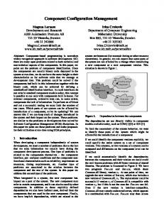
Section 2.1.1 ATM Ce11 Structure ATM is a ceIl (packet) switching concept used in a network. It uses a fixed length ce11 of 53 octets - 48 octets of user data and a 5 octets header. Figure 2.1 depicts an ATM cell.
Nenvork Conjigtirariorz Managemerit 111 Heterogerieo~tsA TM Environments
3
OCTET 5 48 Header Payload BIT
7
8
6
5
4
CI
1
9
3
VPI
GFC 1
VCI
PT
VCI I
1 CLP 1
HEC
GFC: General Flow Control
VPI: Virtual Path Identifier
VCI: Virtual Channel Identifier
PT: Payload Type
CLP: Cell Loss Priority
HEC: Header Error Check
Figure 2.1 ATM Cell In the 5 Octet (byte) header. the distribution of different fields and their functionality are as follows: [2], [3], [4]
Genernl Flow Control (GFC) This field occupies 4 bits and provides a point-to-multipoint connection. It allows mu[tiple users to be connected to the same physical link. i.e, multiplexing the shared network among the cells of the various ATM connections. Virt~ralPath Identifier (VPI), Wrttral Channel Iderttifer (VCI) and Payload Type (PT) These three fields are in coded 8 bits, 16 bits and 4 bits respectively at the User-Network Interface (UNI). At a Network-Network Interface (NNI) the GFC field is replaced by 4 additional VPI bits, which results in a VPI field of 12 bits. These three identifiers support recognition of an ATM ceIl on a physical transmission medium. VPI
Network Configurarion Marrag~nientIn Hererogerieoris ATM Environrnenfs
5
and VCI are unique for cells belonging to the same vinual connection on a shared transmission medium. More details on these two fields can be found in Section 2.1.3. The PT field indicates whether the ce11 is carrying user information to be delivered
transparently through the network, or special network information. C'eu b s s Prioriry (CLP) This field oniy occupies I bit and indicates whether a ce11 has a high pnority (CLP = 0) or has lower pnority (CLP = 1). Le., is subject to discarding in the network. Priorities can be assigned either on a per connection (per VPWCI) b a i s or on a per ce11 basis.
In the first option, al1 cells in the VCNP have the same pnority, while in the second
case, cells within a VCNP may have different priorities. Header Error Control (HEC) Finally, the HEC field consists of 8 bits and is ro protect the header against comption. A polynomial coding algorithm is used to determine if there has been a bit error.
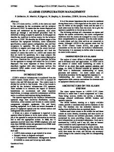
Section 2.1.2 ATM Architecture The sarne seven layered architecture used in OS1 is applied to ATM networks. The Protocol Reference Mode1 ( P h i ) defined in CCITT [ I l , and shown herein as Figure 2.2, is composed of a user plane, a control plane and a management plnne. The user plane transports user information. Example protocols of using this plane are TCP/IP and FïP. The control plane deals with the signalling required to setup, supervise and release a connection. The upper layer protocol for this plane is 4.29 1. The management plane provides two types of functions. Firstly plane management performs manage-
Nenvork Confiurarion Management In Heterogenrorrs A TM Environnients
6
ment functions related to a system as a whole and provides CO-ordination between al1 planes. Examples of this are Simple Network Management Protocol (SNMP) and Common Management Information Protocol (CMIP). Secondly, layer management handles the management functions associated with a particular layer and also the flow of operation. administration and maintenance (OAM) information to a specific layer.
user plane higher layers
higher layers
ATM adaptic n layer ATM layer physical layer
Figure 2.2 B-ISDN protocol reference model For each plane, a Iayered approach is used with an independence between the layers. The physical layer supports pure medium-dependent bit functions and convens the ATM cells stream into bits to be transported over the physical medium. The most commonly
used structure for this layer is SONET (Synchronous Optical NETwork). The main functions of the ATM layer are multiplexing/demultiplexing of cells of different connections into a single ce11 stream on a physical layer, translation of the ce11 identifier and implernencation of a flow control mechanism at the user-network interface (UNI). The ATM adaption layer (AAL) enhances the service provided by the ATM layer. It performs functions
Nenvork Configurarion Managemenr In Hererogeneorts ATM Etivironn~enrs
7
for the user, control and management planes and supports the mapping between the ATM layer and the next higher layer. To accommodate various services, several types of AAL have been defined. These services are described in detail in the next section.
Section 2.1.3 VP and VC Switching In ATM. the transport network functions are split into two parts. namely physical layer transport functions and ATM layer transport functions. This section concentrates on those at the ATM layer [4].
The ATM hyer has two hierarchicd IeveIs, the virtual channel level and the virtual path level. which are both defined in the CCITT Recommendation [Il. Virtlinl chnnnel
(VC) is ' A concept used to describe unidirectional transport of ATM cells associated by a common unique identifier value.' This identifier is called the vinual channel identifier (VCI) and is part of the ce11 header (see Figure 2.1). Krtlinl pnth ( V P ) is ' A concept used to describe unidirectional transport of cells belonging to virtual channels that are associated by a common identifier value.' This identifier is called the virtual path identifier (VPI) and is also part of the ce11 header (see Figure 2.1). The VP concept allows grouping of sev-
eral virtual channels. Conceming the VC and the VP levels of the ATM layer, it is helpful to distinguish between links and connections. A virtital channel link is ' A means of unidirectional transport of ATM cells between a point where a VCI value is assigned and the point where that value is translated or rernoved.' Sirnilarly, a virtiial pnth link is terminated by the points where a VPI value is assigned and translated or removed. A concatenation of VC links is
Nenvork Configurarion Management In Heierogeneorïs ATM Envîronments
8
cdled a virtual channel connection (VCC), and likewise, a concatenation of VP links is called a virtuai path connection (VPC). A VCC may consists of several concatenated VC
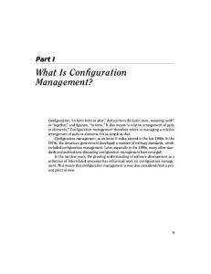
links, each of which is VPC. The VPCs usually consist of several concatenated VP links. Figure 2.3 illustrates the concept of links and connections.
User A
VP Switch ATM A
.
VP Switch ATM C
VP Switch ATM ' B
User B
VPI = 7 VP link
VPI = 5 VP link
-
d d
Switch ATM B
Switch ATM A
User A VPI = 5 VP link
)
VPI = 7 VP link
I
*
Switch ATM
User B
C VPI = 9
VPI = 4
VCI = 14
VCI = 23 VC Iink
1 VC connection
Figure 2.3 ATM Switches: Virtual Path and Virtual Channel Switches VCIs and VPIs in general only have significance for one link [4]. In a VCCNPC the VCWPI value will be translated at VCNP switching entities. VP switchcs (see Figure 2.3) terminate V P links and therefore have to translate incoming VPIs to the correspond-
ing outgoing VPIs according to the destination of the VP connection. VCI values rernain unchanged.
Network Confieuratiorz Mana ~enienlIn Heteroeeneous A TM Environments
VCl 1 VCI 2
9
I 5> ,
VCI 5 VCI 4
1
VCI 5 VCI 4
PI 6)=VCI VCI 12
VP switch
VCI: Virtual channel identifier VP: Virtual path VPI: Virtual path identifier
Figure 2.4 Virtual path switching VC switches (sirnilar to Figure 2.3) terminate VC links and possibly VP links. Both VPI and VCI translation is performed.
VCCsNPCs c m be employed between a user and a user, a user and a network and
3
network and a network. Al1 cells associated with an individual VCC/CPC are transported dong the same route through the network. Ce11 sequence is preserved for al1 VCCs.
ATM operates in a connection-oriented mode. Before cells are transmitted from one user terminal to another user terminal, a logicd/virtual connection setup phase rnust allow the network to perform a reservation of the necessary resources, for instance. bandwidth. After ce11 transmission, the dlocated resources are released. There are two kinds of mechanisrns to set up a connection, namely Permanent Virtual Circuit (PVC) and Switched Virtua1 Circuit. The former is pre-established manually via a network management station at each switch dong the end-to-end path. Telnet in the user plane or SNMPKMIP in the management plane may be used to perform such tasks (see Figure 2.2). The latter is set up
Nenvork Configiirurion Management
/ri
Heterogeneoris ATM Envirortmenrs
10
on demand. based upon signaling procedures like 4.293. The control panel in Figure 2.2 is particularly designed for this purpose.
Section 2.1.4 Quality of Service and ATM Service Classes When providing a service to a customer. the Quality of Service (QoS) needs to be considered. ISO standard defines QoS as a concept for specifying how "good" the offered networking services are. QoS can be characterized by a number of pararneters. The ATM QoS features are mapped into a set of ce11 transfer performance parameters which correspond to the generic criteria of the assessments shown in Table 2.1 [5]:
1 PARAMETER
1 ASSESSMENT
Ce11 Error Ratio(CER) Severely-Error CeIl Block Ratio(SECBR) Ce11 Loss Ratio(CLR) Ce11 Misinsertion Rate(CN1R ) Ce11 Transfer Delay(CTD) Mean Ce11 Transfer Delay(MCTD) Cet1 Delay Variance(CDV)
Accuracy Accuracy Dependability Accuracy Speed Speed Speed
Table 2.1 ATM QoS parameters The above pararneters are based upon an ATM connection. The CER is defined as a number of errored cells divided by the total number of cells transferred during a given connection. The CLR is defined as number of lost cells divided by the total number of transmitted cells for the connection. The CMR is defined as the number of rnisinserted cells divided by the time interval for the connection. The SECBR is defined as the number of
Network Configuration Management In Hererogeneoris A TM Environntents
II
severely errored ce11 blocks divided by the total number of transrnitted blocks. A ce11 block is a sequence of cells ~ansrnittedconsecutively on a given connection, while a severely errored ce11 block outcome occurs when more than a cenain number of errored cells, Iost cells or misinserted cells are observed in a received ceil block. The SECBR c m be interpreted as the probability that an ATM ce11 is discarded. The CTD is defined as the elapsed time between a ce11 exit event at one measurement point and the corresponding cell entry event at a second measurement point for the connection. The MCTD is defined as the statistical average of a specified number of ce11 transfer delays for one or more connections. The CDV is sometimes called delay 'Jitter". Knowing the MCTD and the CDV, the distribution of delays to the ATM cells in ri connection can be determined. It is sometirnes difficult to accurately specify a QoS, as al1 of the parameters of the traffic to be supplied to the network from the customer's premises are not always definable. It has been shown in some research [6] that whilst the long term QoS of the overall network can be predicted. there are so many factors which influence the QoS in the shon term that the network cannot always accurately predict the QoS offered to a customer for each single connection. It is therefore likely that the contract between the custorner and network operator will specify a "best-effort" QoS without providing an absolute guarantee. A specific QoS class provides a quality of service to an ATM virtual connection (VCC or
VPC) in tems of a subset of the ATM performance parameters previously defined in pre-
vious page. The ATM Forum[S] currently defines five different service classes. These account for the variety of traffic types which are intended to be carried over ATM networks. The services offered by the network differ by category. These differences are
Nemork Configuration Management In Heterogeneous A TM Envirorirnents
12
reflected in QoS pararneters and a bnef discussion of each service category and its QoS is given below: Constant Bit Rate Service (CBR) The C B R service is intended for real-tinie applications which require a fixed bandwidth in order to gumntee a minimum end-to-end transmission drlay of the cells.The QoS parameters required for this service class are peak-to-peak CTD,maximum CTD and CLR. This service is categorized as Class A and handled by the ATM adaptation layer AAL 1 by CCITT Recommendation. Real-time Variable Bit Rate Service (rt- VBR)
The rt-VBR service is similar to the CBR service in that it is also intended for realtime traffic. Here. however, the traffic is typically more 'bursty' in nature. The QoS pararneters required for this service class are peak-to-peak CTD, maximum CTD and
CLR. This service is categorized as Class B and handled by ATM adaptation layer AALS by C C l r r Recommendation.
Nort rml-time Variable Bit Rate Service (nrt- VBR)
This service category is the first of the non real-time service categories. It is intended
for bursty traffic types where ce11 loss is still not tolerated. The QoS parameters required for this service cIass are mean CTD, CLR, SECBR and CMR. This service is categotized as Class C and handled by ATM adaptation layer AAL3/4 by CCITT Recommendation.
UnspeciJied Bit Rate Service (UBR) The UBR service category is intended for traditional traffic types such as email or file
Nenwrk Confiiwation hdanagemenr I n Heterogeneoris ATM Errvironnwm
13
transfer applications. This service is categorized as C l a s D and handled by ATM adaptation layer AAL314 by CCIïT Recommendation. Avtlifrble Bit Rate Service (ABS)
For traffic subscribing to the ABR service class, the network guarantees to use the available bandwidth for transmission. The ATM Forum does not specify a corresponding AAL for this category. The "best-effort" QoS may be used for this category.
Section 2.2 ATM Network Management As the communication networks increase in complexity and in size. it becomes essential to use automated network management tools to assist network administrators or operators in monitoring and control of network elements. System network management of ATM covers five subareas, which are discussed in Section 2.2.2. One of the system network manage-
ment deals with the configuration of an ATM network consisting of one or more switches. In this section, an overview of the network management framework is followed by a brief discussion on functional areas of network management. management protocols and management information bases (MLBs).
Section 2.2.1 Network Management Framework A network management system consists of four parts: a management station (or manager),
an agent. a management information base (MIB), and network management protocols. Figure 2. illustrates the relationship among these parts:
14
Nenvork Confiilration Management In Heterogeneozis A TM Environrnenrs
NMS
Network
1
I' 0
MIB
/
\
Network management protocol
1 Figure 2.5 ManagerlAgent Model
The management station serves as an interface for the administrator with the network management system. It translates administrator's commands in to actual monitoring and control of the network elements. Various services provided at the management station include applications for end-to-end PVC provisionin;. Each node in the network that participates in network management contains agent soft-
ware for performing network management-related tasks, for instance, setting up a crossconnection at an ATM switch. Each agent collects data on resources and stores statistics locdly. Agents also respond to commands from the manager. The third component of the network framework is the MIB. An MIB is a collection of objects, each representing a particular aspect of a managed device. For example, a manager performs monitoring function by retrieving the value of available bandwidth at certain port of a switch, and changes the settings of the switch resource by modifying the
Nehvork Confiriration Management In Hrrerogeneous ATM Environments
i5
value of availabie bandwidth. Finally. the communication between the manager and agents is carried out using a net-
work management protocol. The two standard network management protocols are the ETF's simple network management protocol (SNMP) and ISO's common management information protocol (CMIP). In addition to defining a specific protocol. both SNMP and
CMIP define a set of MLBs.
Section 2.2.2 Functional Areas of Network Management ISO defined the following five functional areas for network management. known as
FCAPS [7]: 1. Fclrilt rnanagernent:
The facilities that enable the detection. isolation, and correction of abnormal operation of network resources; 2. Performance nrnnagenrent:
The facilities needed to evaluate the behavior of managed objects and effectiveness of communication activities:
3. Security mnnngemew Addresses those aspects essential to operating network management system correctly and to protecting managed objects; 4. Acco~intingnranagement: The hcilities that enable charges to be established for the use of managed objects and costs to be identified for the use of those managed objects;
Nenvork Confiuration Manaxement In Herero,gerieous A TM En vironntents
16
5. Configuration management: The facilities that exercise control over, identib, collect data from, and provide data to managed objects for the purpose of assisting in providing for continuous operation of interconnection services. Fault management is the process of locating problems or faults in the network. It is a collection of activities required to maintain the desired network service level. Performance management measures the performance of the network hardware, software. and transrnission media. It is a quantitative investigation of the network resources to veriî'y that the service levels are maintained and to support other network management functions such as configuration and fault management. Security management is the process of controlling network access and protecting objects within the network. It involves the protection of the transfer of authenticaiion from one location to another. Accounting management deals with tracking the usage of the network resources by network users and the cost incurred for the service. It is also used to limit the arnount of resources allocated to users and informing them of the costs incurred and resources used. Configuration management is the process of finding and setting up network devices and their resources. It is a set of short and medium range activities for controlling network resource inventory, tracking vendor performance, maintaining trouble files, evaluating and negotiating service levels. managing and changing security levels, and dealing with costs and charging.
Applied to an ATM network including end stations, the configuration management
Network Configuration Management In Hererogeneous ATM Environments
17
requirements include: creating and deleting ATM connections (VPCs and VCCs); getting connection status; determining the number of connections active on an interface; determine the maximum number of connections supported on an interface; determine the number of preconfigured connections on an interface; configunng the number of VPVVCI bits supported.
End-to-end PVC configuration management, which is part of ATM configuration management, is the prime research area for this thesis. For more detailed PVC configuration management, see Chapter 3 PVC Configuration Management for ATM Networks.
Section 2.2.3 Network Management Protocols The managerhgent mode1 presented in Section 2.2.1 performs network management
through the communication between a manager and several azents. The manager controls the overall network management, while the agent adjusts and controls managed objects belonging to it as directed by its manager and reports results back to the manager. Network management requires communication protocol to exchangc information between a manager and the agents. A management protocol provides a means of communication by providing several functions: Reading and updating attributes of managed objects; Requiring managed objects to perform a specific function; Reporting results produced by managed objects; Creating and deleting managed objects.
The two standard management protocols SNMP and CMIP have their own formats and
Nenvork Confipuration Managentent In Heterogeneous ATM Environments
L8
syntax to specify the managed objects, and both employ the managerhgent model. Besides these two standard protocols. some vendors developed their own management protocols for their own devices. T h e following summarizes the two standard management protocols: Simple Nehvork Management Protucul (SNMP):
S N M P was developed by IETF and is widely used to manage TCP/IP networks. It is a connectionless (UDPDP) protocol. The SNMP agents reside on the managed devices and are designed to operate using minimal system resources, not to slow down the operation of the device significantly from providing network manasement services. The agents gather data about a device, which can be either static like system information, or dynamic like traffic packets. and stores them in the ME! residing on that device. The processing of the collected data is done by the management application. The management application communicates with managed devices via a set of SNMP commands. There are many commercial products based upon on SNMP. Co~~lnlon Marzagernrnt Infomntion Protocol (CMIP):
CMIP was developed by ISO. Unlike SNMP, CMIP is designed to provide zeneric solutions to overall network management. It is, however, a sophisticated protocol and is used mainly in service provider [8] networks. While SNMP is based upon a simple common structure, CMIP includes more powerful and difficult-to-develop commands. Accordingly, although CMIP offers more versatility, it is not yet as popular as SNMP.
In particular, currently there are few commercial applications available that use CMIP.
Nehvork Cofrfiicration Management In Heterogeneous ATM Enviroriments
19
Section 2.2.4 Management Information Base The information gathered by the agents is the most important part of the management system, since al1 other activities are based upon it. Thus, much effort has been devoted to defining and standardizing exactly what information is to be gathered and how it is to be stored. MIB standards define network management variables and their rneanings. The vari-
ables themselves are based upon the structure of management information (SMI). The SM1 specifies that the MIB variables be defined and referenced using the ISO abstract syntax notation 1 (ASN. 1). The contents of the SNMP MIB are defined using the SMI, while its structure is defined by the ISO as branch of global object identifier name-space tree. The tree is jointly adrninistered by ISO and ITU-T. Each node in the tree has a name and a number, both of which are unique at that level of particular branch. Through a hierarchical design, the name-space tree ailows individual groups authority over certain branches. as illustrated in Figure 2.6. By following a path from the root to the object, one can detemine the globally unique name for that object.
20
Nenvork Confi,qiirarion hdanagemenr In Heterogeneous ATM Environnrenrs
root
1
I
mib (1)
Aatm(37)
system(1)
Ciçco(9)
Fore(326) atm forum(353)
Figure 2.6 Object Identifier Tree Due to the nature of design differences on each ATM device. each vendor develops its own device MIBs. For instance, Fore has its own MIB for their ATM switches products. while Cisco has their own iMIB for their ATM switches. For more detailed Fore switch MIB and Cisco switch iMIB. see Chapter 3 PVC Configuration Management for ATM networks.
Section 2.3 Mobile Code Based Network Management In the previous section, we overviewed the current network management methodologies. These network management systems tend to be monolithic, require substantial network resources and sometimes huge data transmission over the network. Therefore, they result
Nenvork Configrtration Management In Herero,qeneoris A TM Environnlents
21
in difficulty in maintaining the network and the possibility of causing a bottleneck. In order to overcome these problems, a new technology for network management is developed. The Perpetuum Mobile Procura Project [9], which consists of infrastructure. simulator, network manager and application subprojects, is used to research the use of mobile code for managing networks. Due to its platform independence, mobility. ponability. networking capability and other features. the JAVA prograrnrning language has been chosen for the irnplementation. This section first introduces the fundamental parts of advanced network management based upon mobile code.
[t
then discusses the feasibility of building a PVC Configuration
application using the mobile code.
Section 2.3.1 Motivation for a New Approach to Network Management With the growth of the telecommunication industry, networks have become more and more heterogeneous. A large network is made of devices by different vendors. The software used for managing such a network is even more diverse. To maintain such networks requires attention to compatibility and interoperability. As mentioned in the Iast section, current network management paradigm is built on the client/server model of distributed systems. Apply ing the clienthe~ermodel to network management, agents act as servers, while a manager acts as a client. Agents collect data about the devices and store them in a database but have very limited computational Capabilities. In addition, agents wait for requests from the manager and reply to the manager. It is up to the manager to analyze the data sent by agents. That sometimes causes the bottle-
Nenvork Confilirariori Management In Hererogeneoirs ATM Environments
22
neck on a manager due to big chunks of data durnped to it. Moreover, network management applications are frequently specially designed by vendors for their own devices. Therefore they tend to be monolithic and application is difficult in a multi-vendor environment, In a typical clientIsemer environment, there are many small clients and a large centralized server. The server normally has powerful processing capabilities. In the network management field. there are many agents mnning on devices (like routers, switches) and a centralized management work station (manager). This contradicts the traditional client/ server model. To ease the computation burden on the manager side, a large management task needs to be divided into a set of small, manageable tasks. A new approach to network management based on mobile code is used to tackle the issues. The research of the Perpetuum Mobile Procura Project uses mobile code, or mobile agents [IO].With this nrw approach. agents no longer statically reside on devices. They are mobile, and c m be created o n demand. They can also be destroyed when they are no longer required. These agents tend to perform specific tasks, therefore they are normally fairly small compared to an agent in a legacy network management systern. Funhermore, they can travel from one node to another through a network on a predefined migration pattern. This is advantageous to reduce the network traffic. For instance, in the legacy approach, to perform a management task involving three nodes in a network, the manager has to send a request to and receive a response from the three nodes, while in the new approach, the manager only needs to send a netlet out. The netlet will perforrn the task on each node on behalf of the manager and
Network ConfiRu ration Management In Hrtero,qeneous A TM En vironments
23
report back the result if necessary. In ternis of the nurnber of messages required. the former requires six, while the latter only needs four.
Section 2.3.2 Framework of Network Management with Mobile Code Currently, there is much ongoing research using mobile agents by companies such as Crystaliz, Inc., General Magic, Inc.. GMD FOKUS and International Business Machines Corporation. In order to standardize mobile agents. OMG (Object Management Group) proposed the Mobile Agent Facility Specification [25]. There are also a few applications using mobile agents to do things like providing management functionality where needed [26].
To perform network management tasks with mobile code, it is necessary to have an appropriate infrastructure. Also, to test the design of the mobile code, it is reasonable to use a simulator for the test bed. This subsection introduces the basic components in the infrastructure, followed by a discussion of the simulator.
Section 2.3.2.1 Infrastructure of Mobile Code A facility to transport portable code is a core requirement for solutions based upon mobile
code [9]. The infrastructure of mobile code requires JAVA Vinual Machines (JVMs) [ I l ] running in network components. JVM is a platform dependent interpreter, which translates JAVA code into machine code. At the time of writing, there are also JVM chips available.
Figure 2.3. shows the key components required to send mobile code between running network components. The following discusses these key components [12].
Nenvork Configrcration Management I n Heterug eneous A TM En vironrnenrs
NC: Network Component MCD: Mobile Code Daemon MF: Migration Facility
24
MCM: Mobile Code Manager VMC: Virtual Managed Component JVM: JAVA Virtual Machine
Figure 2.7 Infrastructure of Mobile Code
The MCD is the core component to realize code mobility in order to perform network management tasks. It provides a set of services that enable mobile code execution. These services include: a runtime environment, a migration facility, and an interface to access managed resources.
The MCD is a thread mnning inside the JVM and listens at two communication ports to accepi mobile code. One connection port is TCP, while the other is UDP. Once a piece of mobile code. for instance, a netlet as a mobile agent, is accepted, it is instantiated within the same JVM as MCD is mnning. The MCD also keeps track of al1 handles of instantiated mobile code.
Nenvork Confiil ration management In Heterogeneous A TM Environnlenrs
25
The migration facility is a part of MCD, which is responsible for transponing a mobile agent to the next location. The migration route cm be decided by the application manager, the MCD, or the agent it self. When an agent's migration is requested by an application manager, another agent, or the agent itself, the MCD calls rnethods onMigrate0. This notifies the agent to be transported to the next location. Therefore the agent will have time to finish the task. Whrn the migration is completed, the agent is destroyed and rernoved from the MCD. The ability to access managed resources of a network component is a fundamental in network management. Accessing data in a heterogeneous system may be complex due to non-standard narning schema and procedures. Therefore. there must be a uniform way to be understood by the mobile code in performing its tasks without prior knowledge of the underlying system. The VMC interface makes it possible for mobile agents to access managed resources. The VMC acts as bndge between a mobile asent and managed resources.
Section 2.3.2.2 Network Simulator it is not realistic to expect to test the mobile code in a real network. Therefore a simulator is necessary to test and expenment the ideas and designs. The simulator subproject [13] is
part of the Perpetuum Mobile Procura project. From the perspective of an agent, there is no difference between a simulated and real network component as long as they run MCD that is able to accept and execute netlet code. The simulator, aiso known as a simulated network environment, is made of the simulate control program (SCP) and simulated network components (SNCs). Figure 2.4 shows
Network Configit ration Management In Hererogeneoris A TM Environrnenrs
26
the network architecture.
Simulate Control Prograrn (SCP)
f
JVM
c
C Database (SNCD) /
Simula
SNC
SNC
Figure 2.8 Network Simulator Architecture The SCP is composed of: SCP applet thread. SCP dispatcher thread and the SNC data-
base. The SCP applet presents a graphitai user interface to the human user. Tt takes user input and displays the corresponding results. It also allows the user to manipulate SNC registration information in the SNCD. The user interface has the following functionality: create SNC; manage SNC links; destroy SNC; ship code to SNC; modify SNC MIB dota
The SNCD is the central component of SCP, which contains al1 SNC registration infor-
Nenvork Configuration Management ln Heterogeneous ATM Environrnents
27
mation and link status. Each SNC has fields reaI W o r t and simulated IP/Port. The former is used for communications between SCP and SNC, while the latter is used to sirnulate a real network component. The relationship of the two IP/Port c m be found in the SNCD.
The Dispatcher thread is the component that handles communication between the SCP and SNCs. It is spawned by SCP at start-up time and Iistens for communication requests from SNCs at a pon. The communication is conducted by SCPComrnunicator through a
TCP socket. A simulated network component (SNC) is a collection of JAVA objects running as a thread in JVM. Its purpose is to simulate a real network component such as an ATM switch. It is composed of an MCD, a VMC or sometimes a netlet. The VMC thread has a handle of managed sources, or a MIB object.
Section 2.3.3 PVC Configuration Application Based on Mobile Code Setting up an end-to-end Permanent Virtual Connection in an ATM network is not an easy task. It involves several parties in the route. When the network is cornposed of multi-vendor switches, the task becomes even more complex due to the heterogeneous nature of vendor dependent devices. With the mobile code mentioned in the previous subsection, sirnplifying PVC configuration management becomes feasible. Although different switches have their own ways to store data, they ail perform more or less similar kinds of tasks in terms of PVC configuntion. Using mobiie code. an operator no longer needs to have the knowledge of a specific
Nenwrk Configurarion Managenr ent In Heterog eneous A TM Environments
28
switch. Al1 he or she bas to know is the common representation of the PVC subset of the switch MIB. Upon request to set up an end-to-end PVC, a specialized netlet, namely PVCNetlet is dispatched to each switch to perform the PVC configuration. At each vendor-specific switch, there is a VMC which maps the cornmon representation held by the netlet to the specific switch MIB. The PVCNetlet traverse ail the switches in the path. Due to the difficulty of perfoming the expenment on a real ATM network. the test was conducted in a simulated ATM environment. For more detail of the PVC configuration application based upon mobile code. see Chapter 5.
Nerwork Confilt ration hlanagernent In Hererogeneous A TM En vironments
29
Chapter 3 ATM PVC Configuration Management As one of the ATM network management functions, ATM configuration management is concerned with setting up and releasing the Permanent Virtual Connection (PVC). Due to the connection nature of ATM, before sending traffic cells. the proper virtual circuit needs to be configured. After the virtual circuit is set up, the traffic ceils will then follow the same route. This chapter first analyses the requirement of PVC configuration. It then compares different PVC MIBs in depth. Lastly it introduces the necessity of the cornmon view of a PVC MIB*
Section 3.1 PVC Configuration Requirements ISO defined the five functional areas for network management: Fault management. Configuration management, Accounting management. Performance management and Security management (FCAPS). The main objective of a network management system is to provide the means for communication systems in al1 nodes connected to a network to be monitored and controlled. That is, an important goal is to support an integrated approach to the management of a network which contains multi-vendor devices, software packages and carriers. A configuration management system must have some functions related to resources
(management objects), for example, adding (removing) a resource, such as a switch to (from) a network, initializing a resource and moving a resource around. A configuration
Nenvork Cortfiuration Managentent
In Hererogeneoirs A T M Erivironmerits
30
management system must allow an user to be able to allocate a managed resource, such as bandwidth. Arnong the five network management functions, the PVC management is considered as configuration management function. The requirements for PVC management include:
creating and deleting ATM connections (VPCs and VCCs); getting connection status; deterrnining the nurnber of connections active on an interface; determining maximum number of connections supported on an interface; determining the number of preconfigured connections on an interface; configuring the number of VPWCI bits supponed.
Section 3.2 PVC MIBs One of the key components of the network management frarnework is the MIB [8]. A MIB is a collection of objects, each representing a particular aspect of a managed agent. In
ATM networks each switch has an agent process (agent daemon) running and a corresponding switch MIB. A manager can perforn a monitoring function by retrieving the value of a particular object, for instance, tracing a PVC. As well it can change the settjngs of a network resource by modifying the value of the corresponding object, for instance, setting up a PVC. The communication between the manager and agents is canied out using a network
management protocol. The two standard network management protocols are the ETF's simple network management protocol (SNMP) and ISO's common management information protocol (CMIP). Each protocol defines a corresponding database structure specification and a set of data objects (MIBs). This thesis concentrates on SNMP. The specification
Nenvork Corifi,qurationManagement In Heterogeneous A TM Er1 vironnrents
31
used in SNMP is Abstract Syntax Notation 1 (ASN. 1). Besides these two standard network management protocol. somc switch vendors employ their proprietary protocols and corresponding MIBs. The contents of the SNMP MIB are defined using the Structure of Management Information (SiMI), while its structure is defined by ISO as a branch of the global object identifier (OID) narne-space tree. This tree is jointly administered by ISO and ITU-T. Each node in the tree has a name and a number, both of which are unique at that level of the particular branch of the tree. Through a hierarchical design, the OID tree allows individual groups authority over certain branches, as illustrated in Figure 2.6. By following a path from the root to the object, one can determine the global name for chat object. This chapter compares four SNMP ATM MIBs in the context of PVC configuration. The first two are standard. namely Integrated Layer Management Interface 4.0 (ILMI) by the ATM Forum and RFC 1695 ATOM by Internet Engineering Task Force (IETF). The other two are vendor specific by Fore and Cisco.
Section 3.2.1 ATM Forum ILML 4.0 MIB (UNI 3.1) This section and the next section describe those managed objects from two standard MIBs with respect to contiguring a PVC. While B-ISDN ATM is a definition for public networks. it can also be used within private networking products. In recognition of this fact, the ATM Forum defines two distinct forms of User to Network Interface (UNI) [14]: 1. Public UNI
- which is typically
used to interconnect an ATM user with an ATM
Network Configurarion Management In Heterugeneous ATM Environmerirs
32
switch deployed in a public service provider's network, 2. Private UNI - which is typicdly used to interconnect an ATM user with an ATM switch that is managed as part of the sarne corporate network. The ATM Forum's ILMI covers the both UNI interfaces. The pnmary distinction between theses two classes of UNI is physical reach. There are also some functionality differences between the public and private UNI due to the applicable requirements associated with each of these interfaces. Both UNIS share an ATM layer speciîication, but may utilize different physical media. The term "ATM user" represents any device chat makes use of an
ATM network, via an ATM UNI. Each UNI has a UNI management entity (UME), which maintains the status information of the particular UNI and responds to SNMP messages. The different NMS on either side of the UNI use a pre-specifird virtual circuit to cornrnunicate SNMP messages which
are encapsulated into ATM (ILiMI) cells using AALS. Its VC has the values VPI = O and VCI = 16. The types of rnanaged objects are depicted in Figure 3.1 :
Nehvork Corrfguration Managenrent Irt Heterogeneous ATM Environrnents
if lndex
ifIndex
iflndex tpvi
33
inlndex +vp i+vci
'denotes PVC configuration related group
Figure 3.1 ATM Forum UNI ILMI MI8 The following tables provide a summary of the different managed objects contiiined in the ILMI 4.0 MLB [15] in the context of PVC management. Table 3.2.1.1 describes those managed objects in the Physicd Port Group.
Object
1 Syntax
atmPort Table atmPort Entry atmPort Index atmPort Address
1 Access
SEQUENCE of atmPortEntry SEQUENCE
1
1
Status
1 Description
NA
A list of port entries
NA
A port entry contains information about the physical layer of an ATM interface A unique vdue for each port entry
INTEGER
1
The ATM address for the port
R" Identical with ifName in physical interface group from MIBII
Nenvork Configuration Managemerrt In Hetero,qerteotis ATM Environments
RO
M
34
An IP address to which a NMS c m send SNMP messages to UDP port 161
Table 3.2.1.1 Physical Port Group Table 3.2.1.2 describes those manased objects in the ATM Layer Group.
Syntax Table
of atrnLayer
atmLayer Entry atmLayer Index
SEQUENCE
Description A list of ATM Layer entries
INA I M
INTEGER INTEGER (O...4096) INTEGER (O...268435456)
atmLayer Configured VPCs atmlayerConfiguredVCCs atmLayer Device Type
IRo I M
An entry contains information about the ATM layer of an ATM interface A unique value for each ATM Layer enw The maximum permanent VPCs supported on this ATM interface The maximum permanent VCCs supported on this ATM interface The nurnber of VPCs configured on this ATM interface
INTEGER (O.. .268435&6)
The number of permanent VPCs configured on this ATM interface
INTEGER
The type of the ATM device, end user takes user(1) and network node take node(2)
Table 3.2.1.2 ATM LayerGroup For the purpose of sirnplifying PVC connections. al1 QoS parameters are not considered and only UBR type traffic is transmitted through the network. Table 3.2.1.3 describes those rnanaged objects in the Virtual Path Connection Group in the context of PVC configuration.
Access
Object
Description A list of ATM VPC entries
Status
SEQUENCE
atmVpc Table
of atmVpc Entry SEQUENCE
atmVpc Entry atmVpc PortIndex
An entry contains information about a particular virtual path connection The corresponding physicd port index for a particular VPC connect ion The VPI value of this Circuit Path Connection The present operational status of the VPC, values can be unknown( 1 ), end2endUp(2), end2endDown(3), localUpend2endUnknown(4) and localDown(5) If the value is true(1) the network is required to apply UBR conformance
INTEGER
atmVpc Vpi atmVpc OperStatus
INTEGER (O ...4096) INTEGER
Indicator
Table 3.2.1.3 Virtual Path Connection Group
Table 3.2.1.4 describes those managed objects in the Virtual Channel Connection Group in the context of PVC configuration.
1 Object
1 Syntax
atmVcc Table
SEQUENCE of atmVcc
atmVcc Entry
1 SEQUENCE
atmVcc PortIndex
1
INTEGER
1 Access 1 Status 1 Description
1
I
A list of ATM VCC entries
NA
NI
1 NA
1M
1 An entry conkins information about
1M
a particular virtual channel connect ion The corresponding physicd port index for a particuIar VCC connection
1 RO
1
1
36
Nehvork ConfZlFlrration Management I n Heterogeneous A TM Environnlents
atrnVpc
iNTEGER
RO
M
RO
M
The VPI value of this Virtual Channel Connection The VCI value of this Virtual Chmne1 Connection The present operational status of the VPC, values c m be unknown(l), end2endUp(2). end2endDown(3), locaILJpend2endUnknown(4) and localDown(5)
(O...4096) atmVcc
INTEGER (0.--65535)
atmVpc OperStatus
INTEGER
Table 3.2.1.4 Virtual Channel Connection Group One noticeable observation from ILMI 4.0 LMIB is that al1 variables are Read Only. This is due to lack of security of SNMP v 1.
Section 3.2.2 IETF ATM MIB (RFC 1695) RFC 1695 defines a MIB used for managing ATM-based interfaces, devices, networks and services. Its primary goal is to manage ATM PVCs [16]. The grouped objects are illus-
trated in Figure 3.2.
'interface
ifIndex
interface
interface
'vpl
'vcl
iflndex tpvi
iflndex ivpitvci
'denotes PVC configuration related group
Figure 3.2 IETF ATM MIB
*v~Cross 'vccross
llflndex +Ipvi +hlflndex +hvpi
Ilflndex +Ivpi+lvci thlflndex thvpithvci
aal5Conn
Nenvork Confi uration Management In Heterog eneous A TM En vironnients
37
The following tables provide a surnrnary of the different rnanaged objects contained in the ATM MIB in the context of PVC management. Since this ME3 uses SNMP v2 the headings are slightly different from the ILMI MIB, which uses SNMP vl. Table 3.2.2.1 describes those managed objects in the Interface Configuration Parameters Group. Notice that this group is similar to the Physical Interface group and ATM Layer group from the ILMI MIB.
Object
T
--
-
Description
Access
interface ContTable
SEQUENCE of inetrfaceConfE ntrY SEQUENCE
interface ConfEntry
interface MaxVpcs
1
(0.4096) INTEGER
interface MaxVccs interface ConfVpcs in terface ConfVccs
l
(0..65536) INTEGER
6 INTEGE~
(0..4096)
DJTEGER
(0..65536)
interfaceAd JressTy pe
INTERGER
interfaceMy Neighbour IPAddress
IpAddress
A list of ATM local interface pararn-
eters, one entry per interface port
An entry contains information about the ATM interface, indexed by iflndex in physical interface group oFMIB II Maximum number of vpcs (PVCs) supported at this ATM interface Maximum number of vccs (PVCs) supported at this ATM interface The number of configured vpcs (PVCs) at this ATM interface The number of configured vccs (PVCs)at this ATM interface The type of ATM address configured for use at this interface This value may be obtained either through manual configuration or through L M 1 interaction with the neighbor system
Nenvork Confiquration Management In Hererogeneous ATM Environnrents
38
r
interfaceMy Neighbour IfName
RW
Displaystring
C
This value may be obtained either through manual configuration or through ILMI interaction with the neighbor system --- . -.
Table 3.2.2.1 Interface Configuration Parameters Group An ATM Virtual Path Link (VPL) contains configuration and state information of a iist of bi-directional VPLs. A VPL is terminated in an ATM host or switch and c m be created, deleted m d modified. A VPL entry is indexed by iflndex and vplVpi. Table 3.2.2.2 describes those managed objects in the VPL Group. Notice that this group has the similarity with Virtual Path Connection group from the ILMI M I R
Object
Syntax
Table
SEQUENCE of vplEntry
INTEGER (O. .4096)
I
vpiOper Stotus
I
INTEGER
MaxAccess
1
I
Status
C NA
Description
1 11
I
I
An entry contains information about the ATM VPL information The VPL value of this VPL
C
The current operational status of the VPL, up( 1 ) down(î), unknown(3)
C
The value of MIB II's sysUpTime object at the time this VPL entered its current operational status This object is used to create, delete or modify a VPL
R"
Change
1 Status
A list of ATM VPLs, one bi-directional VPL as one entry
I
Table 3.2.2.2 Interface Virtual Path Link Group Similar to ATM VPL, an ATM Virtual Channel Link (VCL) contains configuration and state information of a list of bi-directional VCLS. A VCL is terminated in an ATM
Nenvork Confitirarion Mana~enlentIn Hetero~eneousATM Environmerats
39
host or switch and can be created, deleted and modified. A VCL entry is indexed by ifindex , vplVpi and vclVci. Table 3.2.3.3 describes those managed objects in the VCL Group. Notice that this group is sirnilar to the Virtual Channel Connection group from
LM1 M m .
Object vc1 Table vcl Entr~ vcl Vpi vcl Vci vclOper Status vplLast Change vplRow Status
I
Syntax
SEQUENCE of vclEntry SEQUENCE
1
kIaxAccess
1
Status
INA I C
1
Description
NA
C
NA
C
A list of ATM VCLs. one bi-directiond VCL as one entry An entry contains information about the ATM VCL information The VPI value of this VCL
NA
C
The VCI value of this VCL
INTEGER
RO
C
TimeStamp
RO
C
RowStatus
RC
C
The current operational status of the VPL, up( 1 ) down(2). unknown(3) The value of MIB II's sysUpTime object at the time this VCL entered its current operational status This object is used to create, delete or modify a VCL
NTEGER (0..4096)
ENTEGER (0..65535)
Table 3.2.2.3 Interface Virtual Connection Link Group An ATM Virtual Path (VP) Cross Connection Group contains configuration and state information of a list of al1 point-to-point, point-to-multipoint, or rnultipoint-to-multipoint VP cross connections. For illustration purposes, only point-to-point PVC connections are considered. A VP is cross connected at a switch or a network and can be created, deleted and modified. The term Low and High corresponds incoming interface and outgoing interface associared with a VPC cross connection. A VP entry is indexed by
Network Corzfgtiration Management 111 Heterogeneous ATM Envirorrmertts
vpCrossConnecIndex,
vpCrossConnecLowIf'Index,
30
vpCrossConnecLowVpi.
vpCrossConnecHighlfIndex and vpCrossConnecHighVpi. Table 3.2.2.4 descnbes those managed objects in the VP Group.
1 Object
hlax-
vpcrossConnecthdexNext
l vpcross !
Connect Table vpCrossCo nnec tEn try
SEQUENCE of vpCrossConnec tEntry
NA
SEQUENCE
NA
vpCrossCo nnec tIndex vpCrossCo nnectLow IfIndex
Iff ndex
vpcross Connect LowVpi
(0...4096)
vpCrossCo nnecHigh Iflndex
Connect HighVpi
Description
Access
INTEGER
Ifindex
INTEGER (0.. -40%)
T h i s object contains an appropriate value to be used for vpCrossConnectTable. A bi-directional VP cross connection which cross-connects two VPLs is modeied as one entry An entry contains information about the ATM VP cross connection in formation
The unique value to identify this cross connection The value of this object is equal to MIB II's incoming iflndex value of the ATM interface port for this cross connection The value of this object is equal to VPI value at the incoming ATM interface with the VP cross connection The value of this object is equal to MIB II's outgoing ifIndex value of the ATM interface port for this cross connection The value of this object is equal to VPI value at the outgoing ATM interface with the VP cross connection
Nenvork Confiirration Managentent In Heterogeneous A TM Envirorrments
The current operational status of the VP cross connect from low to high direction, up( 1) down(2), unknown(3) The current operational status of the VP cross connect from high to low direction, up( 1) down(2)' unknown(3) The value of MIB II's sysUpTime object at the time this VP entered its current operationai status from low to high direction The value of 1MIB II's sysUpTime object at the time this VP entered its current operationai status from high to low direction This object is used to create. delete or rnodify a VP cross connection
L vpCross Connect RowStatus
41
RowStatus
Table 3.2.2.4 Virtual Path Cross Connection Group
* The value O indiccites thar no rinassiglied entries are a v d a b l e . To obtain the vpCrossConnectIndex value for a new entry, the manager issues a 'get' operation to obtain the current value of this object. hfter each retrieval, the agent should modify the value to the next unassigned index. Similar to the ATM VP Cross Connection Group, ATM Virtud Channel (VC) Cross connection Group contains configuration and state information of a list of al1 point-topoint, point-to-multipoint, or multipoint-to-multipoint VC cross connections. For illustration purposes, only point-to-point VC connections are considered. A VC is cross connected at a switch or a network and can be created, deleted and rnodified. The term Low and High corresponds to incoming interface and outgoing interface associated with a VPC
cross
connection.
A
VC
entry
is
indexed
by
vcCrossConnecIndex,
Nenvork Confiii ration Management I n Heterogeneoris A TM Environnzents
vpCrossConnecLowIffndex,
vcCrossConnecLow Vpi,
42
vcCrossConnecLowVci,
vcCrossConnecHighIfIndex, vcCrossConnecHighVpi and vcCrossConnecHighVci. Table 3.2.2.5 descnbes those managed objects in the VC Group.
Object
Syntax
Max-
Status
Description
Access
vclrossConnecthdexNext vcCross Connect Table vcCrossCo nnectEntry
INTEGET (0.214783647) SEQUENCE of vcCrossConnec tEntry SEQUENCE
vcCrossCo nnecthdex
INTEGET ( 0 - 214783647)
vcCross Connect LowVpi
INTEGER (O...4096)
vcCross Connect LowVci
INTEGER (O...65535)
vcCrossCo nnectHigh 1flndex
Ifl ndex
*This object contains an appropriate value to be used for vcCrossConnectTable. A bi-directional VC cross connection which cross-connects two VCLs is modeled as one entry
An entry contains information about the ATM VC cross connection information The unique value to identify this cross connection The value of this object is equal to MIB II's incoming iffndex value of the ATM interface port for this cross connection The value of this object is equal to VPI value at the incoming ATM interface with the VC cross connection The value of this object is equal to VCI value at the incorning ATM interface with the VC cross connection The value of this object is equal to MIB II's outgoing iflndex value of the ATM interface port for this cross connection
Nenvork Corifi,qx~ruiion Managerneni In Heterogeneotrs ATM Errvirorirnerm
Connect HighVpi
(0...4096)
vcCross Connect HighVci
INTEGER (0.,.65535)
vcCrossCo nnectL2H Operstatus
INTEGER
vcCross Connect RowStatus
RowStatus
43
The value of this object is equd to VPI value at the outgoing ATM interface with the VC cross connection The value of this object is equal to VCI value at the outgoing ATM interface with the VC cross connection The current operational status of the VC cross connect from low to high direction, up( 1 ) down(2)? unknown(3) The current operational status of the VC cross connect from high to low direction, up( 1) down(2), unknown(3) The value of MIB II's sysUpTime object at the time this VC entered its current operational status from low to high direction The value of MIB II's sysUpTime object at the time this VC entered its current operational status frorn high to low direction This object is used to create, delete or modify a VP cross connection
Ï--
Table 3.2.2.5 Virtual Channel Cross Connection Group
* The vahie O indicntes that no massigned en tries are n vailable. To obtain the vcCrossConnectIndex value for a new entry, the manager issues a 'get' operation io obtain the current value of this object. After each retrieval, the agent should modify the value to the next unassigned index. Both VP cross connection and VC cross connection groups are available in the ATM
MU3 but are not available in the ILMI MIB since the latter only defines the UNI.
Nehvork Confiurution ~ManagentenrIn Hererogeneous ATM Environnrenrs
44
An ATM MIB is designed in such a way that a PVC can be configured through SNMP, which is not the case with ILMI MIB. The detailed procedures for configuring a PVC is
described in Chapter 5. Any vendor specific switches MIBs which are ATM MIE3 compliant c m use SNMP to configure PVC.
Section 3.2.3 Fore Runner Switch MZB This section and the next section describe those rnanaged objects from two vendor specific
SNMP MIBs wiih respect to configuring a PVC. The Fore switch LMIBdoes not follow either ILMI MIB or ATM MIB. It has its own way to organize the managed objects using SNMP v 1. Figure 3.3 depicts the tree structure
of the Fore switch MIB [17].
Nenvork Configurarion Managenrent In Heterogeneous A TM Environments
45
Contract (10)
(7)
'denotes PVC configuration related group Figure 3.3 Fore ATM MIB The following tables provide a summary of the different managed objects contained in
the Fore switch MIB in the context of PVC management. Table 3.2.3.1 describes those managed objects in the Port Group. Each port entry is indexed by portNumber
Object
numberOf Ports Port Table PO* Entry
Syntax INTEGER
Access
Status
Description
RO
M
SEQUENCE of portEntry SEQUENCE
NA
M
The number of ports at this ATM switch A list of port entnes
NA
M
An entry contains information about this switch port
Network Confiriration hlunagentent tri Hererog eneoits A TM Environnrents
PO* Number portOper Status PO*
INTEGER
RO
iM
A unique vdue for each port entry
INTEGER
RO
M
TimeTicks
RO
M
The current operational status of this port., up( 1), down(2) The length of time this port has been in its current state, in hundredths of a second The ATM address of the entity connected to this port The IP address of the entity connected to this port The maximum number of incoming virtual paths on this port The number of incoming virtual paths on this port The maximum incoming bandwidth on this port, in cells per second The allocated incoming bandwidth on this port, in c e k per second The used incorning bandwidth on this port, in cells per second The maximum number of outgoing virtud paths on this port The number of outgoing virtual paths on this port The maximum outgoing bandwidth on this port. in tells per second The allocated outgoing bandwidth on this port, in cells per second The used outgoing bandwidth on this port, in cells per second
Time portRemote
AtmAddress
AtmAddress
portRemote IpAddress
IpPcddress
portMax PathIns portNum PathIns
IRo I M RO
M
INTEGER
RO
M
GAUGE
RO
M
p o r t ~OC ~f Brindwidthln
GAUGE
RO
M
port Used BrindwidthIn
GAUGE
RO
M
portMax PathOuts portNum PathOuts
INTEGER
RO
LM
GAUGE
RO
M
NTEGER
RO
M
portAllocBan dwidthOut
GL4UGE
RO
M
portUsedBan dwidthout
GAAUGE
RO
iM
portMaxBand
36
widthOut
Table 3.2.3.1 Port Group Table 3.2.3.2 describes those managed objects in the In Path Group. Each entry is indexed by inPathPort and VPI.
Network Configuration Managenient In Hererogerieous ATM Environntents
1 Object
1
1
1
1
1 Syntax
47
1 Access 1 Status 1 Description
inPath Table
SEQLJENCE of inPathEntry
NA
M
A Iist of virtual path entries passing through a port
inPath En try
SEQUENCE
NA
LM
An entry contains information about this incoming path
inPathPort
1 INTEGER
1
Outputs inPathMax 1 INTEGER Channels
1
1 RO
1
1 RO
1
1M
1
1M
1 The value of this object identifies
1 the input port of this path
1
Channels inPathMax Bandwidth
NTEGER
RO
M
inPrithAlloc Bandwidth
GAUGE
RO
1M
inPathUsed Bandwidth
GAUGE
RO
1 inPathUp 1 TimeTicks
1 RO
LM
1M
Time
1
The input of VPI value of this path. The status of this entry The number of output ports to which this path is routed The maximum number of virtual channels that can be allocated on The nurnber of virtual channels that are currently allocated on this path The maximum bandwidth of this path. in cells per second The allocated bandwidth of this path, in ceIIs per second The used bandwidth of this path, in cells per second The length of time this path has been in its current state, in hundredths of a second
Table 3.2.3.2 In Path Group Table 3.2.3.3 describes those managed objects in the Path Route Group. Each entry is indexed by pathrInPort, pathrinvpi, pathrOutPort, and pathrOutVpi.
Object pathRoute Table
Syntax
Access
Status
SEQUENCE of pathR0uteEntr-y
NA
M
Description A list of information about the routing of paths through a port
Network Configrtrarion Management [ri Heterogenemis ATM Environnients
pathRoute Entry pathrInPort
pathrOut Port
pathrMax Bandwidth pathrAlloc Bandwidth
48
SEQUENCE
NA
M
An entry contains information about this path route
INTEGER
RO
M
INTEGER INTEGER
RO RO
M
The value of this object identifies the input port of this path The input of VPI value of this path. The value of ihis object identifies the output port of this path
INTEGER EntryStatus
RO RW
M M
GAUGE
RO
h4
TimeTicks
RO
M
M
-
The output of VPI value of this path. The status of this entry The maximum bandwidth of this path. in cells per second The allocated bandwidth of this path, in cells per second The length of tirne this path has been in its current state, in hundredths of a second
Table 3.2.3.3 Path Route Group Table 3.2.3.4 describes those rnanaged objects in the Out Path Group which is similar to In Path Group. Each entry is indexed by outPathPort and vpi.
( O bject
1 1
outPath Table
outPath Port
outPathMax Channels
Channels
(
Syntax
1 Access 1 Status 1 Description
SEQUENCE
NA
M
of 0utPathEntr-y SEQUENCE
NA
M
INTEGER
RO
M
INTEGER EntryStatus INTEGER
RO RW RO
M M M
GAUGE
RO
M
A list of virtual path entries originating at a port An entry contains information about this outgoing path The value of this object identifies the outpot port of this path The VPI value of this path. The status of this entry The maximum number of virtual channels that can be allocated on this path The number of virtual channels that are currently allocated on this path
Nenvork Confiuration Management /n Heterogeneons A TM Environmenrs
outPathMax Bandwidth
49
The maximum bandwidth of this path, in cells per second
outPathAlloc Bandwidth
GAUGE
The allocated bandwidth of this path, in cells per second
1 Bandwidth I
1 outPathUp 1 TimeTicks
M
The used bandwidth ofthis path, in cells per second
M
The length of time this path has been in its current state, in hundredths of a second
Table 3.2.3.4 Out Path Group Table 3.2.3.5 describes those managed objects in the Channel Route Group which is similar to Path Route group. Each entry is indexed by chanrInPort. chanrInVpi, chanrInVci, chanrOutPort, chanrOutVpi and chanrOutVci.
-t
Object
Syntax
Access
Status
chanRoute Table
SEQUENCE of chanRouteEntry
NA
LM
SEQUENCE
NA
M
1 Port
1
1
chanrlnvpi
chanrOut Port
1
iNTEGER
1
RO
1
M
1
NTEGER
Description A list of information about the routing of channels throught a port An entry contains information about this channel route The value of this object identifies the input port of this channel The input of VPI vdue of this chan-
INTEGER
RO
M
The input of VCI value of this channel.
INTEGER
RO
M
The vaIue of this object identifies the output port of this channel
iNTEGER
RO
M
The output of VPI value of this channel.
INTEGER
RO
M
The output of VCI value of this channel. The status of this entry
IRW I
EntryStatus
1
( M
1
1
Table 3.2.3.5 Channel Route Group
1
Network Cor~figurutionManagement in Heterugenrtous ATM Environmerir
50
The way the Fore switch MIB is designed makes it impossible to use SNMP to configure a PVC.
Section 3.2.4 Cisco LightStream Switch MIB The Cisco LightStream switch MD3 is cornpliant to ATM MIB. Its MIB structure is an expansion of ATM MIE3 structure. Figure 3.4 depicts the tree structure of the Cisco
P
product epend(3) atomis-mib(l4) I
'denotes PVC configuration related group Figure 3.4 Cisco LightStreamSwitch MI0 The following tables provide a summary of the different managed objects contained in the Cisco switch MIB in the context of PVC management. Table 3.2.4.1 describes those
managed objects in the LineInterface Group. Each interface entry is indexed by linflndex.
1 Status 1 Description
IM 1
A list of status of the iine cards including ATM specific information
An entry contains information about a line card A unique value for each port entry, same as iflndex in ME3 II
linf
INTEGER
M
IinfFwd Available Bandwidth IinfBwd Available Bandwidth
INTEGER
M
The amount of bandwidth (Mbps) available/unailocated in the forward (incorning) direction
INTEGER
M
The amount of bandwidth (Mbps) av;iilable/unallocated in the backward (outgoing) direction
,
1
Table 3.2.4.1 Line Interface Group
Table 3.3.4.2 describes those managed objects in the Connection Group. Each PVC connection entry is indexed by connindex. connLowIHndex. connLowVpi, connLowVci. connHighlfindex, connHighVpi and connHighVci.
1 Object 1 Syntax 1 connhdex 1 INTEGER 1
1 Next
l
Table conn Entry conn index connLow IfI ndex
connLow Throughput
1 Access
I
1
SEQUENCE of connEntry
I
NA
SEQUENCE
INTEGER INTEGER
INTEGER
RO
mTEGER
RO
INTEGER
RO
Status
Description The next available index for a row of the connTable A list of current PVCs information. The table is also used to establish and delete PVCs An entry contains information about a PVC connection A unique value for each point-topoint connection The line interface number (iffndex) of the low port. The VPI value of the connection at the low port The VCI value of the connection at the low port The throughput of the connection (Mbps) from the low pon to high port
Network ConfTnuration Mananement
Itr
Hererogeneous ATM Environmenrs
52
connHigh IfIndex connHigh Vpi connHigh Vci
LNTEGER
RO
M
INTEGER
RO
M
connHigh Throughput
INTEGER
The throughput of the connection (Mbps) from the high port to Iow port
LNTEGER
The status of this connection, active( 1), notInService(2), notReady(3), createAnd Wait(4), destroy(5) The result of the PVC establishmeddeletion, existing( I ), vpivciBusy(3),vpivciOutOfRange(3), rateOverflow(4).
The Iine interface nurnber (iffndex) of the high port. The VPI value of the connection at the high port The VCI value of the connection at the high port
-
conncause
INTEGER
Table 3.2.4.2 VPC Connection Group
Section 3.3 Common View of PVC MIB The goal of settinz up an end-to-end PVC based upon mobile code is to provide a uniform way for the ATM network opentor to perform this operation. Thus he or she no longer
needs to know each underlying switch MIB representation in a heterogcneous ATM network. In order to accomplish this, it is necessary to have a common representation, or common view of a PVC MIB. Although di fferent ATM standard organizations and switch vendors have their own ways to present their switch MIBs, in trrms of PVC configuration functiondity, a cornmon view of a PVC MIB can be extracted. Table 3.3 summarizes the cornparison of different M B s based on previous section and the common view of PVC MIB.
vp/vcCrossConnectNexi; vp1vcCrossCorincctIndcx;
vp1vcCrossConnec tLowIHighIfIndex; vp1vcCrossConnectLowIHighVpi;
pvclndex; piitlirIcl~anrIn/O~~tPort; pvcLow/HighIff ndex
vplvcXConnect Index; vp/vcXConnectIndexIn/ outIfi ndex; vpIvcXConnectIndcxln1
OutVpi;
vpIvcXConnectIndexIn1 OutAvailableBw; vplvcXConnectlndexIn/ vp1vcCrossConneiRowStatus; vp1vcCrossConnet Adminstatus;
pat hr/ch;inrS!üiiis
Table 3.3 PVC MlBs and Common View
I
pvcRowStaiiis;
OutThroughpui; vp1vcXConnectRowSiatus
Chapter 4 Different Approaches to PVC Configuration Management As discussed in the previous chapter, configuration management is one of the network
management functionai areas. PVC configuration management plays a very important role in ATM network management. Research activities in this area Vary from integrating existing SNMP based upon configuration solutions to developing more innovative solutions such as using CORB A. Telecornmunication Network Management (TMN) and JAVA.
This chapter analyses different approaches to PVC configuration management in heterogeneous ATM networks.
Section 4.1 Manager to Manager Based PVC Configuration Management The manager and agent mode1 is mentioned in chapter 2 . This section analyses one approach to PVC configuration management in a muIti-vendor ATlM environment [19], [?O].
First. the concept of the network management domain (domain) is to bind a set of managed objects to a specific manager. There can be several agents in a domain, each of which accesses a set of managed objects, as shown in figure 4.1. In the case of PVC provisioning, a domain is specific to a vendor, for example, Newbridge, while the managed objects are
PVC related MIBs, for example, PVC cross connetions. A manager can access a managed object through a related agent. A managed object
Nenvork Configriratiorr Managernerit In Hererugeneotu ATM Environnienrs
56
can be accessed by only one agent. Also, if a manager tries to access a managed object in a remote domain, it has to comrnunicate and negotiate with a remote manager. This is shown in figure 4.1. For multi-domain opention, the multi-domain management protocol (MMP) has to be defined.
Domain 1 configuration manager
Domain 2
MMP
configuration manager
\
\ Agent
Agent
Agent
\
Agent - -
Agent
Obj
Figure 4.1 Conceptual Model of Multi-domain Management
There are some implementations based on this model. For example. research work conducted by Bell Sygma developed an intepration tool for ATM management. The tool manages Newbridge and GDC ATM switches. The key functionality of this tool is end-toend PVC configuration management. Figure 4.2 illustrates the basic ideas of this research. In this system, there are only two domains. namely Newbridge and GDC. The 40620 and NMS 300 are the managers for Newbridge and GDC switches respectiveiy. The NMS 300 manager accesses its GDC PVC resource through SNMP Apex agents. The 40620 man-
Ne fivork Configururion Management In Hererogeneous A TM Environmenrs
57
ager accesses its Newbridge xconnection resource via 36 I~OS, which are Newbridge propnetary protocol agents. In order to integrate two managers, a communication protocol between the two managers needs to be defined.
The advaniages of this approach in a heterogeneous ATM network are: use of existing manager software applications; only require implementing integraiion software between managers: rapid development
Because this approach uses existing software developed by the device vendors. there is no great need to develop new software, except the manager to manager communication software. It takes a relatively small amount of effort to integrate existin; systems.
r
1
.
-
-
,
7
Top-level manager 1
A - - -
Newbridge C
A.
/ 4
40620 manager
MMP WC
GDC
\ \
.
NMS 300 manager
Figure 4.2 Example: An ATM Network Management Tool
Nenvork Configuratiorr Managentenr III Herero,peneoiis ATM Environrnents
58
The disadvantages of this approach are: need different manager software from different vendors; operator has to know dl MIBs from different vendors; integration becomes difficult when the number of vendors grows
Although this approach requires only the integration of existing management systems, it is required to have dl the manager software applications available. This can be expen-
sive to a network composed of many different vendor's switches. Also, the network operator requires knowledge of each MIB for d l the different switches. This is a needless burden on the operator and c m cause human errors. Perhaps the biggest drawback to this approach is when the number of vendor grows. the integration among the multiple vendors will inevitably be difficult. if not impossible. It should be noted that there is another way to handle this kind of multi-manager system. Instead of using a manager-to-manager protocol, a top level manger acting as central manager can be used to comrnunicate with domain managers. These domain managers are mid-Ievel managers and are the vendor specific products. In this rnodel. a PVC con fi,*uration management task is delegated to the mid-level managers by the top level manager. The delegation is normally conducted using scripts. Unlike rnanagerhsents model, there
are no standard protocols. such as SNMP or CMIP, for the communication beiween the top level manager and mid-level managers. At the top of Figure 4.2, the dotted box represents the central manager, while two dotted lines represent the communication between the cen-
tral manager and the Newbridge manager, and the centrai manager and the GDC manager.
Nerwork Configuration Management In Hetrrogeneorrs A TM Environnients
59
Section 4.2 CORBA Based PVC Configuration Management The second approach to PVC configuration management is the use of Common Object Request Broker Architecture (CORBA) [ 2 1 1. The Object Management Group (OMG) initiated the Object Management Architecture (OMA) in recognition of the challenge of the developing software applications and components that suppon and make efficient use of heterogeneous networked systems [ 2 2 ] . C O M A is one of the key components of the OMA.
Two key components of CORBA are OMG's Interface Definition Language ( D L )and the IDL compiler. The IDL specification defines Object Oriented interfaces containing methods and attributes. It also maps IDL onto multiple prograrnrning languages. such as Java. C/C++, Smalltalk and etc. The OMG IDL compiler generates procedure stubs on the client side and procedure skeletons on the server side. Due to its heterogeneous capability, some research work has been done in applying CORBA in network management. Figure 4.3 shows a possible management architecture in a multi-vendor ATM network environment. In the case of PVC configuration management, the IDL represents the PVC configuration common view, which is discussed in chapier 3. The CORBA client. or the end human user only needs to know the common view. The vendor specific switch MIBs are transparent to the client. Interface IDLs distributively reside on different proxy machines. A client can invoke a method: getAvailableBandwidth(). Each IDL translates the available bandwidth from the common view to its vendor specific MIB object. For instance, Interface
Nehvork Confiuration Management In Hererogeneorrs ATM Environmenrs
60
IDLl translates the available bandwidth from the comrnon view to Fore MIB Object, throughput. Some advantages of this approach in a heterogeneous ATM network are as follows: deploying CORBA enabled Web browser: supporting legacy systems; coexistance with current manager platforms
Making use of CORBA follows the trend to develop Web enabled software applications. With the wide use of WWW, this feature is obviously attractive. Supporting legacy systems is perhaps even more important. That means that instead of getting rid of the rnisting systems. they c m be evolved to CORBA. for example from SNMP. Another aspect of using C O M A is coexistence with current manager platforms, for instance, HP Openview.
Neîwork Configurariori Management In Heterogeneous ATM Environnients
61
CORBA
r
Interface IDL1
Interface IDL2
Interface IDL3
r
1
Fore
/
Figure 4.3 An Architecture for Management Systems
in Heterogeneous ATM networks Although the advantages of this approach are appealing, there are some disadvantages. They are as follows:
a "heavy weight" solution: features depend upon services; overkill for srnall applications like PVC configuration
Since CORBA is intended for large network systems, it primarily uses heavy weight protocols. This may cause network traffic problenis. Although on top of CORBA's Object Request Broker (ORB), services like narning service can be applied to fast develop fea-
Nenvork Conjigrrration Management In Hererogencoris ATM Environments
62
tures such as "get/set a MIB object", these feature are normaily expensive. The most important disadvantage of this approach is that for small application like PVC configuration, it is an overkill ta use CORBA, because most of its features are not necessary.
Section 4.3 Mobile Code Based PVC Configuration Management Another way to approach PVC configuration management is to use iMobile Agents. This innovative approach is built upon the mobile code infrastructure and simulator. Both are introduced in chapter 2. As a practical application, mobile code based PVC provisioning tackles challenging issues like heterogeneity and interoperability. Figure 4.4 illustrates the architecture of this approach.
c PVC configuration
manager
PVC Agent
PVC Agent
PVC
-AgenT
Figure 4.4 PVC Configuration Management Based upon Mobile Code
In this approach, the PVC configuration manager sends a PVC agent to the switch at
63
Nenvork Corrfircration Marragemenr ln Heterogeneorrs A TM Environments
one end of the network connection. The agent performs the PVC configuration tasks like setting up a resource, or releasing a resource. Then it migrates to the next switch in the route where it perforrns sirnilar duty. The agent traverses al1 the switches in the route until it finishes al1 configuration tasks. For more information on how this approach works, see
Chapter 5. Compared with the previous two approaches, the mobile code based approach has outstanding advantages. First, there is no manager to manager software integration. The configuration manager has a common v i e ~ of PVC configuration for
üII
different switches.
The operator does not have be aware of the underlying switch systems from different vendors. Although vendor-specific 1MLB information is stored on each switch system, a Switchinterfüce implemented as a VMC is used to translate the common view to the vendor specific MIB information. The PVC agent automates the connectivity procediires
without requiring a human operator's decision making. Secondly. the PVC agents are designed in such a way that they are specialized to perform only PVC related tasks. Therefore, compared to monolithic agents in conventional managerhgents model. they are much smaller, thus cause Iess traffic in the network. Lastly, since Java is chosen to implement the software application. the development time is relatively smail due to lava's 00, portability, networking and other features.
Chapter 5 PVC Configuration Management with Mobile Code in Heterogeneous ATM Environment In the previous chapter, several different approaches to PVC configuration management in heterogeneous ATM networks were discussed, including integrating existing SNMP management applications, a CORBA based solution and a mobile code (JAVA) based solution. From the analysis of the advantages and disadvantages of those approaches. the mobile code based solution is superior to the other solutions. In addition to the advanta,=es mentioned in the previous chapter, the PVC configuration management application fits well in the overall mobile code network management project, which was originated in the Net-
work Management Lab in the System and Computer Engineering Department of Carleton University. This chapter covers developing a PVC configuration management application based upon mobile code in heterogeneous ATM networks. It first proposes the architecture for a new way of PVC provisioning using mobile code. It then analyses the application software requirements, followed by high level design and detailed design and implemcntation. It d s o demonstrates using some examples.
Section 5.1 Architecture of Mobile Agent Based PVC Provisioning Refore the ATM cells transfer from one end of ATM network to the other end, a virtual
Nenvork Configirration Managemenr In Hererogerleous ATM Emironments
65
connection needs to be set up. In this thesis, only the Permanent Virtuai Connection is considered.
In most cases, two enterprises make network connections through some network carrier. Figure 5. i shows the concept of the connection. The top part illustrates the two end switches frorn two enterprises connected through a carrier's ATM cloud. From the network point of view, a carrier's ATLM network can be considered as one switch, according
CO
ATM Forum M4 [23]. The lower part of Figure 5.1 depicts this idea. Pnor to sending ATM traffic. the network operator at one end configures the PVC at its switch as shown in Figure 5.2. He or she then contacts the carrier's operator, either by phone or by e-mail. The carrier's operator configures its switch(es) based on the information given by the end switch operator. After that. he or she contacts the network operator at the other end. The operator ai this end finally configures the switch at this end.
1
S$;ch
1
1-
Carrier's ATM
3-1
r
end switch 1
Carrier's switch
Figure 5.1 ATM PVC Path
,4ich2
end switch 2
Nenvork ConfiRuration Mmagement In Heterog eneoiu A TM En vironrnents
66
With the mobile code approach, only one operator is required. The human operaior enters the end-to-end PVC configuration requirements, such as port connections for neighbouring switches and bandwidth. The PVC configuration application, which serves as a network manager, sends a PVC mobile agent to the network to conduct the configuration task. Depending upon the hnctionality of the task. the agent can be eiiher a PVC setup netlet. a PVC release netlet, or a PVC trace netlet. The agent cames user requirements, accomplishes the configuration task at the switch I end first. then it migrates to the carrier's switch. It does the configuration task at the carrier's switch, then migrates to the switch 2 end. The agent finishes the task at the end switch 2. thus completing the end-toend configuration task. Figure 5.2 illustrates rhis approach. It should be noted that the procedure is sequential rather than parallel. This is because in order to configure the carrier's switch or the end switch. a netlet has to finish the configuration on the previous switch first so that it can carry VPWCI values frorn one switch's outgoing port to next the switch's incorning port. In a non mobile agent approach, each network operator needs to have the knowledge of the switch, in terms of its iMIB. The monolithic agent residing on each switch actually does the work. In a heteropeneous ATM environment, this could be tedious. On the contrary, in the mobile agent approach, there is only one agent travelling through the network and conducting the configuration task. The operator only needs to know the general representation of a switch, or the "Common View" discussed in Chapter 3. At each switch, an interface. called the SwitchInterface is implemented as a VMC, which translates the "Common view" to the vendor specific PVC configuration data. For details see Section
Nenvork CorlflRiiration Management I n Heterogeneous A TM Environnierirs
a
67
I
operator 1
config ure
I
1 configure
fi
configure
switch 2
Carrier's switch
end switch 1
operator 2 end
operator
PVC Configuration Application (Manager)
/
r
end switch 1 1
\
.-(2)
-
-
-
Carrier's switch -
A
'
end switch 2
.-----(3)
Figure 5.2 Non Mobile Code vs. Mobile Code Way of Configuring a PVC Due to the unavailability of a real ATM network for testing the design. a simulation of the network is considered. Figure 5.3 is an example of a multi-vendor ATM network. In this network there can be one or more switches for each of three listed vendors. Here each PVC MIB is unique to a vendor specific switch. Each vendor specific switch interface
(VMC). for example ForeInterface, plays a role of the interface between a vendor specific switch daemon and a simulated vendor switch MLB.
Nenvork Confinration Management In Heterogeneous ATM Envirorinients
68
Figure 5.3 A Simulated ATM Network On each switch, there is a daernon (MCD described in Chapter 3 ) running to accornmodate the PVC agent, or PVCNetlet. which is injected by the PVCConfigurationManager. The PVCNetlet has access to a switchhterface through the switchDaemon. The switch interface maps the "Common View" of PVC knowledge to the vendor specific PVC
MIB. The SimulatedSwitch actually sets the PVC configuration data. Figure 5.4 shows the relationship brtween the cornponents in the PVC configuration application.
The top part of Figure 5.4 shows the components in a simulated environment. The four cornponents inside the square box in the rniddle (Components in a simulated Environment) simulate a vendor specific ATM switch. The ATMSimulatorControlIer is used to access the simulated PVC MD3 on each switch. These MIBs c m be stored in a central database and retrieved on demmd. Each vendor's switch interface is a VMC (see Chapter 2) and can be stored in a Universal Resource Location (URL). When a switch's hardware is updated. a new interface can be brought from the vendor's URL.
69
Network Configitrarion Manag en1enr in Hererugenuoiis A TM Environment
Manager
-
Prn:~ 1 1 Switch lnterface
' SwitchDaemon is a Mobile Code Daemon (MCD)
Components in a Simulated Environment
Ta""h( l
Real Switch
MIB
I
Interface
Manager
Hardware
Components in a Non Simulated Environment Figure 5.4 Model of Mobile Agent Based PVC Configuration Management The lower part (Components in a Non Simulated Environment) of Figure 5.4 shows how a PVC Mobile Agent accesses a real switch which does not run the JAVA virtual
machine. In this case. those components inside the square box in the middle run on a separate host with the real switch. The Switchlnterface needs to implement some native techneque, such as Telnet, to access the red switch MIB.
Section 5.2 Application Software Requirements This section analyses the requiremenis from the user's perspective for the PVC configuration management application software based upon mobile code. Since the purpose of the
Nenvork Confi rtra rion Mariuge»ierir In Hererogeneous ATM Environnlents
70
thesis is to prove the concept of applying mobile code in PVC provisioning management, some of the detailed ATM aspects are taken into less consideration. The analysis makes some assumptions and is not exhaustive.
User interface A Graphical User Interface (GUI), PVCConfigurationManager is required for interacting between the human operator and the application. The GUI should be implemented
as a JAVA Applet. It accepts the bandwidth and the ports information along the ATM PVC path. There is no routing decision to make. It is assurned that the operator has the knowledge of the starting switch, the transit switch and the end switch as shown in Figure 5.2. It is also assumed that only bandwidth is taken into consideration among al1 the QOS parameters when an end-to-end PVC needs to br setup. In other words. the type of the ATM traffic is going to be "best-effort", as mentioned in Chapter 2. Initial network setup When the network is created, al1 pons on each switch are initialized. The PVCConfigurationManager does not dynamically discover the network. The human operator must have knowledge of pon inter-connections between switches in the network. Setup end-to-end PVC The operator should be able to just specib the ports on start, transit (carrier) and end switch and required bandwidth. The end-to-end PVC setup is completed in two stages. Stage one involves the resource reservation, while stage two involves the resource commitment. The software should first check the resource (bandwidth, VPVVCI) availability on each switch. If there are insufficient resources, an error message should be displayed. After that, the software should allocate the resources along the path
Nehvork ConfTRurarion managern ne nt In Hererogeneoiis A TM Environments
71
including the start switch. the end switch and the transit switch. Trace end-to-end PVC(s) The operator should be able to trace either certain end-to-end PVC or dl end-to-end PVCs by specibing the pons on the start, transit and end switches. The software should display bandwidth, VPI and VCI values on each switch with specified ports on start, transit and end switches.
Release end-to-end PVC(s) The operator should be able to removr a designatrd, previously allocated end-to-end PVC or al1 end-to-end PVCs by specifying the ports on stm, transit and end switches.
The software should rernove those PVC(s), and release the previously allocated resources on each switch with specified ports on start. transit and end switches.
Section 5.3 Appiication Software Analysis This section analyses the requirements from the software designer's perspective for the PVC configuration management application software.
Section 5.3.1 Mapping PVC Common View to Vendor Specific MIB In the requirements analysis from the user's or network operator's perspective, the end user interface is transparent in terrns of the underlyinp vendor specific switch. Al1 the end user is aware of is the general switch PVC representation, or the "Common View" (which is analysed in Chapter 3). Because the actual PVC configuration needs to be done at each vendor specific switch, it is required to have a kind of mapping, or translation from the "Common View" to a vendor specific switch PVC M m .
Nenvork Configrrration Management l n Hetero~eneous.4 TM Environrnents
72
To materiaiize this rnapping, a software component, called SwitchInterface, is developed based upon the mobile code infrastructure. It is a subclass of abstract class VirtualManagedComponent and acts as a bridge between a mobile PVC Configuration agent. PVCNetIet, and a vendor specific switch MIB. It is preinstalled with a switch netlet daemon. Therefore, when the PVCConfigurationManager wants to conduct some task. say setting up an end-to-end PVC, a PVCNetlet with a "Common view" is launched by the application manager to a switch daemon at the start end of the network path. The netlet then gains access to the SwitchInterface. The SwitchInterface in turn obtains access to the underlying switch. After completing the task on one switch, the netlet migrates to the next switch. Figure 5.5 depicts the procedure.
operator PVC Configuration Application (Manager)
Figure 5.5 Mapping Common View to Vendor Specific Switch For more details on the SwitchInterface component, see Section 5.4 and Section 5.5.
Nenvork Cortfiguration Management In Hererogerreous ATM Envirormenis
73
Section 5.3.2 Scenario Analysis Based upon the user's requirements frorn the last section, several end-to-end PVC configuration scenarios, narnely PVC set up, PVC trace and PVC release, are analysed in terms of preconditions, postconditions, assumptions and algorithms:
Set up end-to-end PVC In this scenario, the end user (network operator) enters the port information for the start switch. the transit switch and the end switch, plus the required bandwidth for the trafic. The PVC setup is conducted at the allocate resource stage and the commit resource stage.
Assumption: The trafic class is UBR, in other words, it is "best-effort" traffic. Among al1 the QOS parameters, only the maximum bandwidth needs to be assigned prior to sending actual traffic at the virtual connection stage.
Preconditions: - The physical port connections are known;
- Each port's resource capacity, Le. the number of VPWCI and maximum bandwidth (available bandwidth) are given.
Postconditions: - Each switch's cross connection is set up if there is resource available. Othenvise,
exception message is displayed.
Algorithm:
Nenvork Configuration Managemerit
In Hererogeneorrs A TM En vironmen rs
at the start switch, Jind the oritgoing port nt the port, senrch for the jrst available VP with the required bandwidth at the VI? search for the jrst nvailable VC with the reqriired bandwidth retrirn VPI and VCI;
clt the trnnsit switch j n d the incotning port crt the port, search for thefirst available
VP with the required batzdwidth
nt the VP, senrch for the first available VC rvith the reqrrired bandwidth jtid rke oritgoing port crt the port, senrch for theJirst nvailctble VP with t h r-rq~iiredbnndrvidth cri the
VP, searcli for the jrst availuble VC rvith the repirrd banhvidth
retrrnr irzcorning VPI and VCI, and olrtgoitzg VPI and V U :
crr the end sivitch, Jind the incorning port
at the port, search for thejïrst nvnilablr VP with the reqriired bnndtvidth nt the VR senrch for thejrst available VC rvitlz the requit-ed banhvidth retrirn VPI and VCI;
cornmitResorirce() for rach sr-vitch, do crossConnection
74
Netkvork ConfiRuration Management Iri Heterogeneous A TM
En virorinlenrs
75
ctddConnection decreaseResott rce
Trace end-to-end PVC(s) In this scenario, the end user (network opentor) enters the pon information for the start switch, the transit switch and the end switch.
Preconditions: - There exists PVC(s) at the given start switch and end switch via the transit switch.
Postconditions : - A collection of PVCs at given path are retrieved.
Algori thm: [rt the stc~rrwirch, j n d the oritgoing port
tu the port. find VP LLI
the VP.j n d VC
rrtirnl tlre porr ririniber; VPI, VCI and baridwidtir ot tire orttgoirzg port;
at the trcmsit switch
find the irrcorning port nt the port, jïnd VP at the V c find VC
filrd die oritgoing port ctt the port. Jind VP at the V e f i d VC retiirn the porr nttrnber; VPI, VCI and barrdwidth ut the iricoming ctnd the oritgoing
Nerwork Conflgrtrarion Managent enr In Hetero~eneorlsA TM Envirortmenrs
76
port;
at the end swirch. j n d the incoming pon nt the port, fiid VP
at the VP,$nd VC retirrn t/ir port n~rnber:VPI. VCI and bnndrvidth nt the incorni>zgporc Release end-to-end PVC(s) In this scenario, the network operator wants to free the PVC between the start switch and the end switch, which has been previously set up. The consequence of this scenario is: alon; the PVC path. al1 related resources, Le bandwidth, VP and VC at the each switch are released.
Assump tion: There is no traffic dong the path.
Preconditions:
- There exists PVC(s) at the given start switch and end switch via the transit switch. Postcondi tions: - The end-to-end PVC is removed and ail resources are reciaimed.
Algorithrn:
at each switch do
jrid the specified cross connection reniove the cross connection increnseResource
Neiwork ConfiRuration Mattagentent In Heterugeneoiis A TM Environments
77
Section 5.4 High Level Design This section covers the high level design issues of the software implementation. It describes the required software components in the mobile code based PVC configuration application and the necessary classes.
Section 5.4.1 Software Components Figure 5.1 illustrates ail the software components in the PVC Configuration Management Application. This thesis develops the application in a simulated environment. Therefore the access to a real vendor switch is not covered. From the figure. software components SimulatedSwitch, SwitchInterface. PVCNetlet. SwitchDaemon. PVCConfigManager and ATMS imulatorController are the core components. The SwitchDaemon is implemented as a MCD, which is a part of the mobile code infrastructure. To extend the SwitchDaemon from the general MCD. the only consideration is the configuration file. which contains important parameters. such as the TCP/UDP listening port. Switchlnterface VMC, SimulatedSwitch VMC and migration route. in order to accommodate the PVCNetlet. The following discusses the remaining core components of the PVC configuration management application based upon mobile code in a simulated environment.
SimulatedSwitch: This component is a subclass of VirtualManagedComponent, which contains the vendor specific PVC MD. It is decomposed into ATM physical layer interfaces, which in turn contain multiple virtual path links. Futhermore a vimial path link c m be decom-
Network Configriration Manugenrent In Heterogeneoirs ATM Environn:ents
78
posed into multiple virtual channel links. Both virtud link and virtual channel link are at the ATM layer. Depending upon the vendor, a physical layer interface c m be a port, or a line c a d . For each vendor, a more specific simulated switch is required. For instance, a ForeSimulatedSwitch. which contains multiple physical ports, is required to sirnulate a switch by Fore.
SwitchInterface: This component is also a subclass of VirtualManagedComponent which translates the general representation. or the "Common View" to a vendor specific PVC MIB. It has access to the SimulatedSwitch. For each vendor. a more specific switch interface is required. For instance. a ForeSwitchInterface, which contains an access to a ForeSimulatedswitch, is required to rnap the Common View to Fore specific switch in a simuIated manner. This VMC can be expanded to perform other tasks like updating switch software
PVCNetlet: This component is a subclass of Netlet. which performs PVC configuration related tasks. A PVCNetlet only has knowledge of the Cornmon View of a switch. It is not aware of the underlying vendor specific switch. When a PVCNetlet is injected by a PVCConfigManager it carries user requirements for a configuration task. After the Netiet arrives on a SwitchDaemon, it obtains the reference pointer of the
Swi tchlnterface. It then passes the user requirements to the Switchlnterface. The latter in turn passes the requiremenr to the SimulatedSwitch. The SimulatedSwitch finally configures itself. PVC configuration task can be setting up connection, trace connec-
Network Confiuraiion ~ManagenrenrIn Heterugeneous ATM Environrnents
79
tion or release connection. Depending upon the configuration task, a specialized PVCNetiet can be used. Three kinds of these Netlets, namely PVCSetupNetlet. PVCTraceNetlet and PVCReleaseNetlet. are developed to achieve the three different goals. A PVCNetlet c m migrate from one switch to another depending upon the configuration task. For more detail. see Section 5.5.
PVCConfigManager: This graphical component serves as an interface between the end user, or network operator, and the application software. It ttdces end-to-end PVC configuration requirements from the user (such as port number and the bandwidth) and launches a specialized PVCNetlet to a start switch
CO
perform one of three tasks: setting up a PVC,
tracing PVCs or releasing a PVC. In addition, the PVCConfigManager needs to know the IP address of a start switch.
ATMSimulatorController: This component is a modified version of SimulatedControlProgram (SCP), which is mentioned in Chapter 2. The purpose of this component is to have access to the individual vendor specific PVC MLB. This graphical component can display each simulated switch's PVC M m . In addition, as an alternative means of installing SimulatedSwitch VMC and S witchlnterface VMC on each SwitchDaemon, it can ship these two VMCs to each SwitchDaemon, which does not install the two VMCs at its starting up stage.
Nenvork Configuration Management In Heterog eneous A TM En virurinterrrs
80
Section 5.4.2 Class Diagrarns In the previous subsection, the functionaiity of each core cornponent in PVC Configuration Management application was discussed. This subsection analyzes these components from an Object-Oriented view. Al1 the class diagrams use Object Modeling Technique (OMT) notation [24]. Rectmgular boxes represents objects. The association among objects is represented by a line between them. The diamond at the end of a line represents a containment relationship. The diamond is located next to the object which is contained in
the other. Figure 5.6 is the class containment diagram for the Common View of an ATM switch. Each ATMSwitch object contains multiple Port O bjects and multiple CrossConnection objects. A Port can be at either the incorning side or outgoing side of an ATMSwitch. Each Port object is made of multiple VPLink objects, which in turn consist of multiple VCLinks. A CrossConnection object has fields: index. inPortNum. inVpi, inVci. outPortNum. outVpi, outVci and bandwidth.
Lrl ATMSwitch
index inPortNum inVpi inVci outPortNum outVpi outVci bandwidth Figure 5.6 Cornmon View of ATM Switch
81
Nework Configrtrntion~Mana.gementIn Hererogeneorts ATM Erivironmertrs
Figure 5.7 is the class inheritance diagram for simulated switches. The SimulatedSwitch object is a subclass of ViualManagedComponent object, while the SimulatedForeSwitch, SimulatedCiscoSwitch and SirnuhtedNewbridgeSwitch are subclasses of SimulatedSwitch.
VirtualManaged
1
Simulated ForeSwitch
1 1
1
Simulated CiscoSwitch
Simgfed ewbrid eSwitc
1
Figure 5.7 Sirnulated Switches Similar to Figure 5.7, Figure 5.8 is the class inhentance diagram for switch interfaces. The SwitchInterface object is a subclass of VirtualManagedCornponent, while the ForeSwi tchlnterfxe, CiscoSwitchInterface and NewbridgeSwitchInterface are subclasses of
Switchlnterface.
VirtualManaged
1
I
Fore Switchlnterface
1 1
Switch interiace Cisco switchlnterface
/ 1
Newbridge Switchlnterface
1
Figure 5.8 Switch Interfaces Figure 5.9 shows the class inheritance diagram for PVC netlets. The PVCNetlet object is subclass of Netlet, while PVCSetupNetlet, PVCtraceNetlet and PVCReIeaseNetlet are
Nenvork ConfiRururiori Muna~enienrIn Neferogeneous A TM Environmenrs
82
subcIasses of PVCNetlet.
1
I
PVC
Figure 5.9 PVC Netlets Figure 5.10 illustrates the class relationship of the PVC Configuration Management Application. A PVCConfigManager contains either PVCSetupNetlet, PVCtraceNetlet or PVCReleaseNetlet. Depending upon the configuration task, one of three PVCNetlet has access to ForeSwitchInterface, CiscoSwitchInterface and NewbridgeSwitchInterface. These three switchlnterfaces contains SimulatedForeSwitch. S imulatedCiscoSwitch and
SirnulatedNewbridgeSwitch respectively.
1
1 1
Switchlnterface Fr;e
Switchlnterface cis;
[ ForeSwitch (
[ CiscoSwitch
1
1
[_ Switchlnterface Newb,ridge 1 bewbridge~witcd
Figure 5.10 Class Relationship of PVC Configuration Management Application
Nenvork Conj?g~irarionManagemerit
/ri
83
Heterogeneoiis ATM Environrnenrs
Section 5.5 Detailed Design This section covers the design issues in a more detailed manner. The interaction of different classes in a PVC configuration management application is illustrated in message interaction diagrams for three different scenarios. namely setting up a PVC, tracing PVCs and releasing a PVC. The high level algorithms for these scenarios are shown in Section 5.3.
Section 5.5.1 Setting Up End-to-end PVC Scenario In this scenario, objects PVCConfigManager, PVCSetupNetlet, Fores witchhterface. SimulatedForeSwitch,
CiscoSwitchhterface,
SimuIatedCiscoSwitch.
NewbridgeSwitchInterface and SimulatedNewbridgeSwitch participate in an end-to-end
PVC set up. Figure 5.11 illustrates the message exchanges among these objects. The end-to-end PVC setup is accornplished in two stages. In the first stage. the necessary resources Le. bandwidth. VPVVCI. are reserved at each vendor specific switch. Then in the second stage, the reserved resources are allocated. The advantage of dividing this procedure into two phases is that in case there are insufficient resources at a certain switch, there is no need to deallocate the resources at a previous switch. For example, the resources are allocated at the SimulatedForeSwitch first. but there are not enough resources at SimulatedCiscoSwitch. In order to undo the allocation of the resources at the SimulatedForeSwitch, the PVCSetupNetlet needs to go back that switch to release the resources.
84
Nehvork Confiltration Management I n Heterogeneous A TM Environrnenrs
Section 5.5.2 Tracing End-to-end PVC Scenario In this scenario, objects PVCConfigManager, PVCTraceNetlet, ForeSwitchInterface, SimulatedForeSwitch,
CiscoSwi tchhterface,
SimulatedCiscoS wi tch,
NewbridgeSwitchInterface and SimulatedNewbridgeSwitch participate in end-to-end
PVC tracing. Figure 5.17 illustrates the message exchanges among these objects.
Section 5.5.3 Releasing End-to-end PVC Scenario In this scenario, objects PVCConfigManager, PVCReleaseNetlet, ForeSwitchInterface, SimulatedForeSwitc h,
CiscoSwitchInterface,
SimulatedCiscoS witch,
NewbridgeSwitchInterface and SimulatedNewbridgeSwitch participate an end-to-end
PVC releasing. Figure 5.13 illustrates the message exchanges among these objects.
Nework Configrtraxion Mana~ernentin Heterogenrcoris ATM Environment
85
PVCConfig Manager
PVCTrace Netlet
Fore
Simulated
Cisco
Simulated
Newbridge
Simulated
Switchinterface
ForeSwitch
Switchhterface
CiscoSwitch
Switchlnterface
NewbridgeSwitch
Figure 5.12 Message Interaction Diagram for Tracing PVC Scenario
PVCConfig Manager
PVCRelease Fore Netlet Switchlnterface
Simulated
Cisco
Simulated
Newbridge
Simulated
ForeSwitch
Switchlnterface
CiscoSwitch
Switchinterface
NewbridgeSwitch
Figure 5.13 Message Interaction Diagram for Releasing PVC Scenario
Network C o r z ~ u r a t i o r zMariagement in Hererogenuous ATM Environnlenr
88
Section 5.6 Implementation The prototype implementation for mobile code based PVC configuration management application is written in JAVA. For detailed source code, see Appendix.
Section 5.7 Testing Examples This section illustrates some testing examples of the PVC configuration management application software, including setting up end-to-end PVC and tracing end-to-end
PVC(s). The program simulates a Fore Runner switch at one end and a Newbridge 36 150 switch at the other end with
ri
Cisco LightStrearn switch as a carrier's switch (transit
switch). Figure 5.14 is the image of the user interface of the PVC configuration manager. The testing is run on a Pentium PC with Window NT. To nin [he program, the proper class paths, where al1 required JAVA classes are. need to be set up first. In order to run three switch netlet daemons, which simulate three switches. three DOS consoies are required. Change to the directory where SwitchDaemon configuration files are located and type the following at these consoles: At DOS Console1 (sirnulates a Fore's Runner switch): [type]: java nict.NetletDnernon startPVCnetletdaenron.properties
You will see the daemon installation messages like:
mct.admin.Mobile CodeManager: Instnntiator is irzstalled pvc. vrnc.nrib.SinitilntedForeSivitchhas been installed strccessfirlly ForeSwitchlnte@nce hus been installed successfidly pvc. ~~mc.sivitchlrrterfc~ce. mct.adniin.Listener: Wnitingfor TCP connection ut port 8998
Nencork Corifitrrarion Mariagernenr In Heterogeneo~rsATM Erwironrnenrs
Vendor Switches:
89
Connection Parameters:
1
Start Outgoing Port
Carrier's Switch: Cisco LightStream End Switch: Newbridge 361 50
Carrier's Incoming Port
Carrier's Outgoing Port End lncoming Port
7 1 1 2 1
Bandwidth (in BPS) I
Start Switch TCPAP: Hast
pGEÏ-
TCP Port
End-to-end PVC Configuration Functions:
Applet started.
Figure 5.14 PVCConfigManager
DOS Console2 (simulates a Cisco's LightStream switch): [type/: ju v a tnct.NetletDaetnon trnnsitP VCnetlrtdrienioiz.prop~ies You will see the daemon installation messages like:
mct.adnin.MobileCocie11.Innager: Instnntiator is iristalled pvc. vmc.tnib.SinzrdntedCiscoS>vitclt has been itistolled sirccessfidly pvc. vmc.sivitclilriterface. CiscoSwitclilnterface h m been instcrllrd s~rccrssfidly mct.ndtnin.Listener: Waitingfor TCP connection at port 7998
At DOS Console3 (simulates a Newbridge's 36150 switch): [type]: java mct.NetletDaemon endPVCnetletdaemon.properties
i
i
Nenvork Configuration Management In Hererog ericous A TM En vironments
90
You will see the daemon installation messages like:
mct.ndmin.MobileCodeMarzager: lnstantintor is installed pvc. vmc.mib.Sim~ilatedNewbridgeSwitchhns been installed siiccessficlly pvc. vmc.switchlnte~ncr.lVeivbridgeS~t~itc~~Interfc~ce /ras been instnlled s~iccessfiilly
mct.admin.listener: Wnitingfur TCP connection ut port 6998
Now you have three simulated switches running and are ready to launch PVCNetlets to perform PVC configuration tasks. To set up an end-to-end PVC at the above simulated ATM network connection. click the Setup button at the PVCConfigManager. You wil! see the following results at the three
DOS consoles: At DOS Console1 (simulates a Fore's Runner switch): PVCSetripNetlet got the hnndie of pvc. virzcsi.vitclrInterfrice.ForeIr~teflc~ce Start switch nt outport: 2 Bandividdz: 100 CrossCorznection: -1 - I - 1 3 0 0 100 A b o to ~ migrate...
Note: At CrossConnection output, there are seven fields. The first three fields represent the port number, VPI and VCI at the incoming port. The next three fields represent the port number, VPI and VCI at the outgoing port. The last field represents the bandwidth for this PVC. Here the first three fields are - 1, w hich means the incoming port information is not
appl icabie.
At DOS Console2 (simulates a Cisco's LightStream switch):
Nenvork Configurarion Managerner~rIn Hetrrogeneorrs ATM Environniettts
91
PVCSetupNetiet got the hnndle of pvc.vmc.sivitchlnte~ace.Ciscolnte~ace Transit switch nt inport: 1 Transit switch at outport: 3 Bandwidth: 100 CrossConnection: 1 0 0 3 1 0 100 Abotlt tu migrate...
At DOS Console3 (simulates a Newbridge's 36150 switch): PVCSetupNetlet got the han& of pvc. vmc.s~vitclzln~t..fc~~e. NewbrdgeInterface
End switch at inport: 2 Bnrrdwidth: 100 CrossConnection: 2 1 O -1 -1 -1 100 To trace end-to-end PVC(s) at the above simulated ATM network connection, click the
Trace button at the PVCConfigManager. You will see the following results at the three DOS consoles:
At DOS Console1 (simulates a Fore's Runner switch): PVCSetupNetler got the handie of pvc. vrnc.switclzlnte@~ce.ForeInterface Start switch nt oirtport: 2 CrossConnection: -1 - 1 -1 2 0 0 100 About to migrate...
At DOS Console2 (sirnulates a Cisco's LightStream switch):
P VCSetcipNetletgot the handle of pvc. vmc.srvitchlnte~~~ce. Ciscolntegkce Transit switch at inport: 1
Nenvork Configurarion Management In Heterogeneous A TM Environmen rs
92
Transit switch nt outport: 3 CrossConnection: I O O 3 I O 100 Abolit to migrate...
At DOS Console3 (simulates a Newbridge's 36150 switch):
P VCSetlipNetlet got the handle of pvc. vmc.srvitchlntr~'ice.NewbrdgeInterface End srvitch ar inport: 2 CrossConrtection: 2 1 O - 1 - 1 - 1 100
The examples presented here show the results under normal circurnstances. In the example showing the setup of a PVC, there are sufficient resources at each ATM switch for the end-to-end connection to succeed. If there are insufficient resources at some switch. an error message will be displayed. In the example showing uacing a PVC, the cross connection information is displayed at each switch because the connection was set up pnor to the request for a cross connection trace. If the request came before the setting up of the cross connection. an error message at each switch will indicate that there is no cross connection.
Nenvork ConJgrc ration Managenrent In Heterogeneous A TM Environmen ts
93
Chapter 6 Conclusions This chapter concludes the thesis. It first s u m a r i z e s the thesis' work in tenns of the contributions to the current PVC configuration management. It then discusses some future work.
Section 6.1 Summary Network configuration management is a difficult task. It becomes even more complex in heterogenrous ATM networks. In this thesis. a new approach to PVC configuration management is proposed. The new approach is an application to the iMobile Code infrusttruture developed in the Network Management & Artificial Intelligence Lab of the Department of Systems and Computer Engineering.
In order to overcome requiring knowledge of the PVC configuration MIB for each individual switch in an ATM network for network operators. the thesis introduces ü T o m mon view". With this PVC configuration "Cornmon View", a network operator does not have to be aware of PVC configuration MIBs for different vendor switches. A piece of software component acts as an interface to map the "Common View" to each vendor specific PVC configuration data. A software application. called PVC Configuration Management In Heterogneous
ATM Environments was developed. It was tested using Mobile Agents to perform end-toend PVC configuration tasks. such as setting up, tracing or releasing end-to-end PVCs. A prototype implementation of the software application was created. It consists of
Newark Confi,qtmfionMarragenienr
hi
Hererogeneorts ATM Environrnenrs
94
twenty two classes and 6000 lines of JAVA code. With its graphical user interface. which is what a network operator would see, a user can choose among different PVC configuration functions. The underlying software launches a specific Mobile Agent depending upon the user's choice of PVC configuration tasks. 1 believe the implementation of management features using Mobile Agent approach
reduces the complexity of the irnplementation. The creation of a single purpose agent reduces the interactions among ne twork management features. which c m on1y reduce implementation time. This single purpose agent. because it is small. is also likely to be smaller than the data transfered arnong nodes as compared to the monolithic agent approach. A drawback of the approach presented in this thesis is the inability to use it on real systems right now. The ability to migrate from one node to another in the network using a Mobile Agent is large achieved because the Java Virtual Machine (JVM) provides the device independence from the perspective of a computing platform on which the Mobile Agent is run. At this time, I am unaware of any JVMs for in-service ATM switches.
Section 6.2 Future Work The scope of this thesis and the time constraints were such thot is was impossible to implement every idea. The nature of the thesis work was experimental, which leads to iterative refinement of the software. It is hoped that the work will be carried on in the future, with the possible irnplementation of the following: The current program is based upon simulating a multi-vendor switch ATM environ-
Network Confittrarion Managemenr In Heterogeneous A TM En vironments
95
ment. The software cornponent. which acts as an interface between the "Common View" of PVC configuration data and actual vendor switch PVC MIB does not have the capability to access PVC MIBs for real switches in a functioning ATM network. The software needs to be refined so to accommodate real ATM switches. The ports connection brtween nsighbouring ATM switches are static. An end user requires the pon connection knowledge due to lack of auto discovery capability in the Mobile Code framework. After the auto discovery functionality is implemented. the user interface in the PVC configuration software should be able to launch a port connection Mobile Agent and display the connection data on the user interface. Arnong al1 the ATM PVC connection parameters, only the maximum bandwidth is currently considered. In the future the program shouid be refined so that the application can incorporate other connection requirements. such as the Ce11 Error Ratio or Ce11 Loss Ratio
for the ATM traffic.
Nenvork Configurarion Management In H erero~eneousA TM Environnients
96
References: Integrated Broadband Networks -- An Introdrrction to ATM-based Nehvorks, Addison-Weisley, 1991 Mdfidedin: Comprrting, Conmirnications und Applications. Innovative Technolosy Series, 1995 Uyless B lack, ATM:Fo~rndcition For Broadband Netivorks, Pren tice Hall Series. 1995 Martin DePrycker, Asynchrun~roirsTrcrnsfer Mode: Solution For Broadband [SDN, EIlis Honvood, 1995 The ATM Forum Technical Comrnittee, ATM User-Network Inte@ice Specificotiori V 3.0, The ATM Forum 1993 Alexander, P. & Carpemer. k.. ATM Network Management: A statrrs Repart, Data Communications pp. 1 1O- 116. September 1995 Stallings, W., SNMP, SNMPL~L. and CMIP, The Proticai Guide tu Nehvork hfcuurgement, Addison-Wesley, 1993 Onvura, O., Asynchtonorrs Trmsfer Mode Networks, Pe flomnnce Issues, Artec h House, 1995 Perpetuttm Mobile Procura Projecl, http://www.sce.carIeton.ca~netmanage/perpetuum.shtm1, 1997 [ 1O]. B ieszczad, Toivnrds Plrrg-and play Networks with Mobile Code. Tech. Report SCE-
97-08, Dept. Systems and Cornputer Engineering, Carleton University, March 1997
Nenvork ConfSgriration Management In Heterog eneotts A TM En vironments
97
[ 1 11. The Java Virtiral Machine Specification, Tech. Report, Sun Microsysterns, 1996 [ 121. G Susilo, A Bieszczad, & B Pagurek, Infrastnictrire for Advanced Nenvork Manage-
ment Based on Mobile Code. 1996 [13]. Campeau A., Managing Neenvorks with Mobile Code. Tech. Report SCE-97-09, Dept.
Systems and Cornputer Engineering, Carleton University, April 1997 [ 141. The ATM Forum, ATM User-Nenvork Intujkcr Specijïccrtion V3.1, Prentice Hall,
1997 [ 151. The ATM Forum Technical Committee, Integrnte kzyer Management Irlteg?zce V4.0,
The ATM Fomm, 1996 [ 161. M. Ahmed & K-Tesink, Reqrrest for Comnrents: 1695, Internet Engeneering
Task
Force 1994 [ L 71. Fore Systems Inc., forethorrght-3.4..r.niib,(private communication) 1996 [ 181. Cisco Systems Inc., Cisco LightStrerrrrr WB,(private communication) 1995
of a ConJig~trcltionMartagemerzt Sys[19]. Kwang-Hui Lee, Design arid Irnplement~~tion
rem, Globe Telecom, 1993 [20]. Bell Sygrna, CANARIE ATM Nenvork Mrrtirigement Integrntion Tools User Guide, (private communication) Apnl 1997 [2 11. The Cornmon Object Reqriest Brokec Arclzitecture and Specifcntion 2.0 ed., Object Management Group, July 1995
[ X I .Steve Vinoski, CORBA: Integrating Diverse Applpications Widiin Distribrlted Heterogeneous Environments, IEEE Communications Magazine, Vol. 14, No.2, February, 1997
Network Configuration Management
In Heterogerreaus A TM Environnlents
98
[23]. ATM Forum Technical Commiitee, M4 Intevace Reqitirements and Logical MIB,
ATM Forum, October 1994 [24]. J. Rumbaugh, M. Blaha, W. Premerlani, F. Eddy & W. Lorensen, Object-Orientecl Modeling and Design, Pretice Hall, 199 1
[XI.Mobile Agent Faciliry Specifcation. OMG TC Document cf/xx-x-xx, June 1997 [Xi]. Busse. 1. Covaci, S ., Ciistorner Facing Cornponr~itsfor Nenvork Mcmngement Systenis. Integrated Network Management V, Proceedings Fifth IS WM, San Diego,
iMay 1997
TEST TARGET (QA-3)
-
APPLIED & IMAGE. lnc
= 1653 East Main Street -. . NY 14609 USA ----,Rochester. Phone: 716i482-0300
---
Fax: 716/288-5989
O 1993. Appliad Image. IK. All Rights Reserved


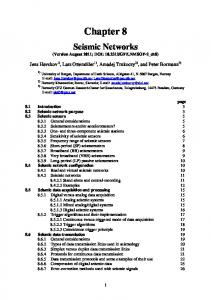


![Network Configuration Management with NETCONF and YANG - IETF [PDF]](https://m.moam.info/img/260x300/network-configuration-management-with-netconf-and-_6486b19b098a9ec6178b45a7.jpg)