Dilger, J. Frank, J. Hoagland, K. Levitt, C. Wee, R. Yip and D. Zerkle, 1996. GrIDS-A graph- ... Spafford, E.H. and D. Zamboni, 2000. Intrusion detection using ...
World Applied Sciences Journal 13 (11): 2372-2384, 2011 ISSN 1818-4952 © IDOSI Publications, 2011
Network Intrusion Detection with Wiener Filter-based Agent Mouhammd Al-Kasassbeh Department of IT, University of Mutah, Karak, Jordan Abstract: Over the years, network attacks have evolved into more complex and sophisticated methods for network intrusion. As network domains become bigger in terms of size, the number of external users increases and thus the systems become more open and subject to security threats. Thus, the intrusion detection system was introduced to automatically detect network attacks. Commercial solutions however are generally centralized and suffer from scalability problems when applied in large networks. For this reason, in this paper, the distributed model was adopted to eliminate the scalability issues. Mobile agent combines with statistical methods based on the Wiener filter to collect and analyze the network data in order to detect anomalous behaviour in the network traffic. The algorithm was tested against four network attacks in both light and heavy traffic scenarios. Key words: Mobile agent variables
•
distributed network management
INTRODUCTION As the Internet grows network security incidents increase at the same time with the attacks evolving into more complex and sophisticated methods for network intrusion. The security of traditional networks was based upon mechanisms and policies deployed on the operating system. These methods [1] proved to be insufficient because of the flaws they generated that consequently lead to security vulnerabilities. Thus, Intrusion Detection Systems (IDS) were introduced as components of the security system aiming to improve the implementation of countermeasures. IDSs play an important role in modern computer network systems by providing an additional layer of security. Usually organizations implement firewalls to prevent Unauthorized access into their network; but firewalls cannot detect unauthorized behaviour in the network traffic that is allowed to go through. On the other hand [2], IDSs analyse various event streams on the network and identify manifestations of attacks. Over the last 10 years, the IDS has become a fundamental component of an organization’s computer network system helping to protect its most valuable asset and its network infrastructure. The majority of today’s organizations are computer dependent and any attack on their network could prove catastrophic. Recently, many organizations experienced a series of attacks from Internet worms, which infected their computers by exploiting vulnerabilities and selfreplicating in order to spread through the network. This
•
wiener filter
•
intrusion detection
•
MIB
resulted in a degradation of performance and denial of service in some cases. The Code Red worm in 2001 propagated to over 359,000 Internet hosts in less than 14 hours, Then in 2003 the Slammer worm propagated to over 75,000 hosts in less than 30 minutes, 90% of which were infected within 10 minutes [3]. Because of the nature of this attack, worms can rapidly spread throughout the whole network causing enormous damages. In order to counter this rapid self-replication and detect the attack in its early stages, network administrators deployed IDSs in a distributed manner covering the entire computer network. The majority of the existing IDSs perform data collection and analysis by using a centralized monolithic architecture [4]. Generally centralized intrusion detection suffers from significant limitations when used in large and slow speed networks which causes scalability problems. Because the data are processed on the server it consumes processing power and bandwidth that may lead to a late response to an attack. In addition because each IDS is developed for a specific environment it is difficult to adapt the detection mechanism to different patterns of usage. As a result it limits the flexibility of the centralized paradigm. A Distributed IDS (dIDS) on the other hand consists of multiple IDSs over a large network where they communicate with each other or report to a central node about instant attack data and network monitoring related data. The communication between the central node and the IDSs is based on multiple mobile agents deployed in different areas of
Corresponding Author: Dr. Mouhammd Al-Kasassbeh, Department of IT, University of Mutah, Karak, Jordan.
2372
World Appl. Sci. J., 13 (11): 2372-2384, 2011
the network and geographical locations [5]. By transferring the code to their destination the agents help in terms of scalability and adaptability. Since the code is not executed on the manager node but at the agent’s destination the manager node’s workload and traffic is reduced. A Mobile Agent (MA) is a software entity with a well defined role that travels between network nodes, acting on behalf of a human or another software component [6]. Agents maybe static or mobile and can migrate between network nodes and carry code and state information in order to perform a computation; providing a new and useful paradigm for distributed computing. Unlike the client-server computing paradigm, relationships among entities tends to be more dynamic and peer-to-peer, stressing autonomous collaboration [7]. Several dIDS were introduced so far but none of them seems to perform rapid and efficient detection. Also they are based on the unidirectional traffic changes which result in serious false alarms when legitimately abrupt changes appear [8]. This means that a distributed attack such as Distributed Denial of Service (DDOS) which is among the most prevalent threats might be reported by the dIDS as a false alarm. The aim of this study is to detect intrusion attempts at the local nodes with the use of Management Information Bases (MIB) variables and statistical methods based on the Wiener Filter that detect anomalies in the behaviour of traffic. The theory behind the filter will be discussed and suggestions will be made for enhancements and modifications so that the agent can report the anomalies that exist in the network traffic. CHALLENGES IN NETWORK INTRUSION DETECTION The main challenges in the area of intrusion detection are scalability and late detection. Apart from these, there are also some challenges after collecting the data from the system. Because each network uses different components and deploys different services, it is difficult to understand the dynamics of traffic from one network to another. For example, a common problem in anomaly intrusion detection is that it is based on statistical rules that can be different from one network to another. It is therefore difficult to decide whether the traffic is normal or abnormal because in each network apply different conditions and what is normal in one of them could be abnormal in another. Moreover the majority of IDSs use the MIB as a data source but not a single MIB variable can provide information regarding the cause of the system. The difference in my work here and the
previous work [9] is in this study, it has been not based on statistical rules so it is independent as it will be shown later in this paper. However all statistical algorithms used in intrusion detection, including the one used in this paper, suffer from inaccuracies because there is no accurate statistical model for normal traffic that can be mathematically modelled to be compared with the abnormal one. Also the existing statistical algorithms are based on change detection methods which produce different results [10]. PREVIOUS WORK IN THE AREA OF INTRUSION DETECTION Existing Distributed IDSs (dIDS): The concept of an IDS was first introduced by [11] but it was really born after Denning [12] published her intrusion detection model. Denning’s IDS and others that followed were centralized and based on a monolithic architecture. As previously mentioned, this means that data are collected and analyzed on a single machine. In order to eliminate the problems of centralized ID which were discussed earlier [13, 14]. [15] introduced the distributed IDSs where data collection and information analysis was performed without central authority. The researchers had provided a solution to the scalability problem but since the IDSs were static they faced the risk of being directly attacked. In order to deal with the problem of centralized processing [16, 17] introduced the EMERALD and AAFID respectively. These systems are probably the two most cited among the various dIDS that were introduced during the last 5-10 years. They deployed multiple component IDSs in different locations and organized them into a fixed hierarchy, where the low-level IDSs send the intrusion relevant information to the high-level IDSs. The hierarchical approach provides a solution to the scalability problem but the detection of distributed attacks is not performed in an efficient way. Moreover the majority of these dIDS are based on the unidirectional traffic changes which result in serious false alarms when legitimately abrupt changes appear [18]. This means that in a distributed attack case such as Distributed Denial of Service (DDOS) which is among the most prevalent threats, the dIDS might report it as false alarm which would lead to catastrophic events. The cause of the problem is in the underlying anomaly-based detection techniques employed by these dIDS. Anomaly-based detection techniques: This section outlines the anomaly-based detection techniques that IDSs use in order to perform the task of detecting the unusual traffic through the data.
2373
World Appl. Sci. J., 13 (11): 2372-2384, 2011
Frequency-based detection: This technique was one of the first anomaly detection methods introduced by [12]. It captures frequently patterns of users and software through profiles that contain abnormality values corresponding to a set of measures (variables). In order to determine if the system had experienced an abnormal event, the observed frequency values are combined through an expression which captures frequency information for all the measures using a series of weights [19]. The technique computes on a permanent basis the security level and compares it with a threshold value in order to detect the intrusion. Expert systems: According to [20] an expert system is a computing system capable of representing and reasoning about some knowledge-rich domain with a view to solving problems and giving advice.[21, 20] and [19] are some examples where expert systems were used in intrusion detection. This detection technique is classified as anomaly detection because it explicitly specifies the patterns to look for. [19] The expertise of the security officer that will be used as input to the detection mechanism is an important factor that affects the success of the technique. Also the effectiveness of the implementation, to utilize the expertise of the human into a computer, plays an important role as well. Expert systems have been used to combine various intrusion measures in order to produce a good view of the intrusion. However the well known limitations of this approach for doing uncertainty reasoning have stopped the progress in the area. Bayesian networks: The detection models based on Bayesian learning use probabilistic relationships among different measure variables [22]. This information is used to create belief networks in order to graphically represent casual dependencies between random variables. Furthermore this technique can be used in a network in order to calculate the probability of an intrusion depending on different variables such as when the number of logged-on users is high but the CPU load is low. This probabilistic framework helps for early detection by distinguishing between normal and abnormal behaviour within the information. Statistical analysis: A new approach in intrusion detection and fault management has recently been introduced by [18, 23, 24] which is based on statistical analysis. These detection techniques are characterized by their simplistic operation and their performance that rivals the Artificial Intelligence (AI) techniques. These characteristics helped to create great interest in these techniques in the fields of intrusion detection and fault. The statistical analysis methods monitor the relevant
MIB variables that relate to the IP traffic and at an early stage of the process they apply change detection such as General Likelihood Ratio test (GLR), Log Ratio Test (LRT) and CUSUM. [25] These detection techniques have the ability to operate both online and offline, with the online approach being deployed most of the time. Moreover the change detection techniques are based on sliding windows with hypothesis testing algorithms. The learning and testing windows are being tested by the algorithms and if the degree of variance of a specific property of between these two windows rises above the threshold, then the change is reported. In our previous work [9], We proposed a statistical analysis approach which is based on the Wiener filter for detecting network faults. Unlike the other approaches, this one does not have a fusion centre or a change detection algorithm and thus it achieves rapid detection and response to network faults. Moreover the algorithm is cloned into several agents and executed concurrently in all the sub-domains and their relevant equipment. Since the underlying theory of detecting faults and intrusions is the same, here in, the algorithm will be applied as a network intrusion detection system and then with a series of experiments the algorithm will be tested in order to identify whether it can detect intrusion attempts. THE MODEL OF THE NETWORK BASED-AGENT At present, the most popular model for distributed computing is the Client-Server paradigm (CS). Conversely, with rising demands on processing power and the need to conserve bandwidth on large and slow networks, the restrictions of this approach has become conspicuous. The CS model is suitable for the applications with a limited need for distributed control [26]. Undoubtedly, this limits the flexibility with which a client can use a server, by processing the server data locally according to the client's needs. Thus, the mobile code-computing paradigm was introduced [27]. With this paradigm, the data and the code are transmitted together between the client and the server. Transmitting the code to the d estinations helps in terms of scalability and adaptability. An MA could migrate between nodes, carrying the necessary code to be executed [28]. MAs offer a real benefit to the system developers and the users. MA applications specifying which parameters can be improved upon, for example performance, connectivity, reliability and modularity. The importance of these key parameters may vary from one application to another. After the relevant discussion in my previous work based on using MA in the area of network fault
2374
World Appl. Sci. J., 13 (11): 2372-2384, 2011
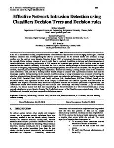
Fig. 1: Distributed processing using MA.sub-domain setup management [29], we conclude that for early fault detection and real time detection, the management functions must be very close to the managed devices. This can also be implemented by the MA technology. These agents can travel, communicate with each other and clone themselves, if that is needed in order to accomplish the main management tasks in a distributed way. However, the agents need to access the managed devices and also need to have enough knowledge about the management functions to discover the faults locally and raise alarms if necessary. In this paper, the agents design will be examined and the Wiener filter that is the algorithm they operate with to make them capable of accomplishing their missions in an efficient way. For instance, these agents need to access the MIB variables from each node, they monitor. Therefore some methods need to be added to make the agents able to communicate with existing management data, together with numerous powerful algorithms to make these agents capture the abnormal conditions in different network nodes. In other words, the agents, as shown in Fig. 1, can be dispatched to the remote subnets. Each agent can draw the topology of the subnet virtually, by accessing the routing table and then deciding which main nodes are in the domain, such as routers, switches, hubs, servers, printers and gateways. The agents will start collecting the MIB variables from these nodes and process their management functions. In our experiment, the Interface (IF) and Internet Protocol (IP) MIB variables have been considered. The router has been chosen as one of the subnet's main nodes. In this case, the original agent will start with the process of cloning itself to cope with the number of the interfaces in that router. So, if we have three interfaces, four simultaneous agents are needed: one for the IP MIB variables and the other three for the IF MIB variables. One agent monitors each interface.
The agents start to check the health condition for that router based in the algorithm they have. Finally, the output from each of these agents will be tackled by using alarm correlation techniques to have the final output as a health indicator for that router [30]. Choosing the management protocols and the MIB variables had been already examined in our previous work [9], In our experiment, this work followed Thottan’s [10] router case study. The Interface (IF) and Internet Protocol (IP) group of variables are of interest to our attack detection algorithm. The IF group has a table, with an entry for each system interface. The total number of network interfaces is given by the ifNumber variable of the IF group. This group deals with features like operational status of an interface, a count of the number of received or sent octets. The IF group has information related to the type of technology that the interface has used, the current bandwidth, the interface status, statistics about the traffic and error counters. For IP group, it gives similar information about the traffic but in a cumulative way, in addition information about IP address table and IP routing. In order to observe more information from these variables and apply some statistical methods, more preparation is needed. Such preparation may include converting these data to time series by differencing each variable and then applying some statistical methods to extract more information. In the next section, we will describe the experiment, the design of the subnet, the collection of data and finally, the testing of the agents. For collecting the traffic from a network a simulator can be used to model the network or the signals can be monitored in real time. OPNET is a widely used network traffic simulator but it lacks the ability to simulate attacks for the model or manage data properly. Another network simulator that can be used in live monitoring is the AdventNet. This tool has the ability to collect most of the MIB variables but not the
2375
World Appl. Sci. J., 13 (11): 2372-2384, 2011
Fig. 3: Sending and receiving data with LanTraffic
Fig. 2: The testbed of the experimen network attacks involved in this experiment due to their nature. Therefore it was decided that a network should be set up to collect the desired data from a sub-domain while performing four different network attacks on it. The experiment was conducted in the lab of the IT department at Mutah University. As shown in Fig. 2 the network consists of one PC router, two switches and two subnets. The first subnet contains two PCs, one of which is going to be used for launching the attacks. In the second subnet there are also two PCs one of which is going to act as a server/victim in the experiment. In the next paragraph a description of the laboratory setup and the software used in the experiment. •
PC Router: the PC router has two network interface cards to be a router [Processor: Intel (R) Pentium (R) 4 CPU 2.80GHZ, Memory: 2 GB, Network adapters: Intel® PRO/100 VE Network Connection, Routing protocol: RIP, OS: windows XP] PC: PC with [Processors: Intel(R) Pentium (R) 4 CPU 2.80GHZ, Memory: 2 GB, Network adapters: Intel® PRO/100 VE Network Connection, OS: windows XP] Switch: Cisco Systems Catalyst 2900 Series XL 24 Port Switch 24-Port 10 Base T/100 Base X.
simulate a real network so that the environment is as realistic as possible. For this reason the LanTraffic V2 was used to generate background traffic. This tool allows the user to define data size and packet parameters as well as the delay between each packet sent. In order to test the agent in different environments it was decided that the experiment should be conducted using two scenarios, a heavy network traffic scenario and a light traffic scenario. As shown in Fig. 3 the LanTraffic software was installed on all the machines to act as a sender and receiver. The local and destination IP addresses were configured so that a PC could a sent TCP, UDP or ICMP packets to another PC and vice versa. This allows for a simulation of a real client-server or a distributed application. THE AGENT MODEL FOR ABNORMAL TRAFFIC DETECTION
In general, most of network management paradigms whether centralized, decentralized or distributed deploy some kind of polling scheme to manage devices in order to get their MIBs variables and subsequently began their management sequence. Nevertheless, each paradigm has a different workload • on the manager station as well as different bandwidth requirement. The whole study about the polling issues and the workload in the main management node has been explored in our previous work [29] and also in • [32]. In the model, both the mobile agents and the CS polling system are used to explore and monitor the To collect the MIB variables, we have developed a devices in each sub-domain or subnet. JAVA code using the classes of SNMP Agent Toolkit The main part of this paper is the agent itself. The Java Edition 6 [31]. The data collection was repeated agents have been upgraded with statistical algorithm for each attack, under heavy and light applications. The based on Wiener filter [33]. Using these statistical variations in these eight collected datasets allow us to methods and the sampling of the MIB variables examine the operation of the network in more details. sequence that reflects the current traffic state of the The network was divided in two subnets (1.1.1.1 subnet at regular intervals allow the agent to detect and 2.2.2.1) as shown in Fig. 2. On the computer network faults, by generating network health alarms. running as the server an Apache web-server and a The agent will run in the system for a 24 hour period FileZilla FTP service were installed. Since this network during the normal traffic. During this period, the agent is isolated from the Internet, traffic needs to be builds information from learning the history of the generated between these two subnets in order to network that is also updated when it is convenient from 2376
World Appl. Sci. J., 13 (11): 2372-2384, 2011 Layer Health x(n )
y(n)
Linear filter of input signal
MIBs
∑
IF layer
d(n )
Fig. 4: Agent processing
e(n)
d ∧ (n)
Linear filter of desired signal
1.5 1
1
Threshold max
Second Fault
0.5
Fig. 6: Our proposed wiener filter for Network fault detection
0.5 False Alarms
0 0
-0.5 -0.5 Average Abnormality Indicator Threshold min -1
-1
First Fault -1.5 -1.5 0
10
20
30 Time in Mins
40
50
60
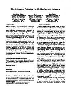
Fig. 5: Alarm declaration from the agents time to time. When an agent is dispatched to subdomain, it runs remotely or locally on the polled devices, depending on their types. As mentioned earlier, if the device is a router or a printer, the agent performs remote polling; on the other hand, if the device is a server, the agent performs local polling. The agent starts checking the sequences of MIBs immediately after receiving them against a threshold, as shown in Fig. 4. Through the normal traffic, the agent calculates the adaptive threshold using the correlation matrix from the network history file. As shown in Fig. 5, there are two thresholds labelled min and max. Any value from the indicator falling inside these thresholds represents a healthy node otherwise an error condition is reported.
The health indicator for the system e is evaluated by polling the monitored devices. As shown in equations 1, to calculate e, the correlation matrix R for the input vector and the desired signal vector, as well as, the tap vector of the filter coefficient R are required. The input signal variance and the desired signal variance help us to find the network health indictor on line. As we can see in Fig. 6, the filter coefficient W has been calculated for the input and the desired signals. The coefficient W is calculated by the correla-tion matrix of the signal itself and cross-correlation between the two signals. ε = σd2 − σ y2 = ε w Td R d w d − w Ty R yw y ε = 1−
(1)
T y T d
w Ry wy w R d wd
Specifically, the input vector is the MIB variables of the IF level or the IP level. Therefore, the length of the filter is different from one level to another. At the network level, the filter length is four representing the four MIBs variables and at the IP level the length of the AGENT DESIGN WITH WIENER FILTER filter is three representing the three the MIB variables. Initially, these MIB variables are polled during the One of the filters that have been used to observe normal operation of the network for duration of 24 the original signal from the noisy signal is Wiener filter hours or more. The calculation of the variance of the [33-35], which is developed using time domain. The normal traffic is then obtained, which is important for main idea of Wiener filter is to minimize the Mean the online traffic comparison. To calculate the variance, Square Error (MSE) between the desired output and the the correlation matrix of these MIB variables is actual output from the filter itself. In our research, we evaluated in every polling session, as well as, the crosshypothesize that abnormality of the network traffic can correlation vector between the desired sequence d(n) be captured using the minimum mean square error and the input sequence x(n). The same steps are MMSE (e) indicator with the Wiener filter. performed on the input sequence; consequently, the The desired signal in our case is the normal traffic value of e will be straightforward to calculate. This obtained during the 24 hours of operation or more of process will be repeated during every polling time, the network. It could be presented as the whole time which is adaptive and online to check the change of signal or as an average. The input signal on the other the traffic and then decide whether it is an abnormal or hand will be the online traffic coming from the system. 2377
World Appl. Sci. J., 13 (11): 2372-2384, 2011
normal situation in the traffic. The calculation of the vectors, matrices, variances and the network health indictor will be presented next. The filter coefficients of the Wiener filter of length Lw , as shown in Fig. 7, involves the calculation of the set of filter coefficients Wk(n), k=0, Lw-1 in order to produce the mean square estimate y(n) of a given process d(n) by filtering a set of observations of a statistically related process x(n). Let x(n) and y(n) denote the input sequence and the corresponding output to the filter, then y(n) can be expressed as L w −1
∑w
= y(n)
k =0
k
(n)x(n − k )
(1)
The desired sequence d(n) is the signal with which the filter output y(n) is compared. The error sequence e(n) is e(n) = d(n) − y(n) = d(n) −
L w −1
∑ w (n)x(n − k)
k =0
k
(2)
In order to make the filter response best match the desired signal, the coefficients of the filter are selected to minimise the power of the error signal, i.e. the MSE, according to the given criterion defined by a cost function ξ(n) [33] as; 2
ξ(n) = E e (n)
(3)
(7)
results in the set of Lw linear equations with Lw unknowns Wk(n), k=0, Lw-1 , that yield to the optimum filter coefficients: L w −1
∑w k =0
k
(n)rxx (k − m) = rdx (m) , m = 0, Lw-1
(8)
Using the definition of the autocorrelation matrix R0 and the cross-correlation vector rdx(k) given in [33] as T
R 0 = E x(n)x (n)
(9)
one can write the matrix form as wR 0 = rdx
(10)
(4)
(5)
IMPLEMENTATION
2 Lw - 1 ξ (n) = E d(n)- ∑ w k (n)x(n-k) k =0
where, by definition = rdx (k) Ed(n)x(n − k)] [
∂ξ(n) = 0 , m=0, Lw- 1 ∂wm
where W is the filter vector of length Lw consisting of the filter coefficients. To directly solve this set of linear equations, known as Wiener-Hopf equations [35], it is necessary first to compute the autocorrelation sequence rxx(k) of the input signal and the cross-correlation sequence rdx(k) between the desired sequence d(n) and the input sequence x(n). Hence, the statistics of those signals should be known in advance, as well as they are necessary to compute the sequences rxx(k) and rdx(k) at each sampling instant.
or
L w -1 = E d 2 (n) - 2 ∑ w k (n)rdx (k) + k =0 L w - 1 L w -1 ∑ ∑ w k (n)w l( n ) rxx (k-l) k =0 l =0
Fig. 7: The general wiener filtering problem
The IF and IP MIB variables collected from the router, as shown in Fig. 8 demonstrates one of the main nodes from Fig. 1. This Router for example has two The signal statistics rdx(k) is the cross-correlation interfaces. As mentioned earlier, the router will have between the desired output sequence d(n) and the input three agents; IPAgent and two IFAgents. Although sequence x(n) and rxx(k) is the autocorrelation of x(n) these agents deploy the same algorithm of Wiener filter, [33, 34], the input signal and the length of the filter are different The cost function ξ(n) is a quadratic function of in each. the filter coefficients. Consequently, the minimisation In the router, at the Network Level for instance, there are four MIBs variables called ifInUcastPkts of ξ(n) with respect to each of the filter coefficients (ifIU), ifInNUcastPkts (ifINU), ifOutUcastPkts (ifOU) W(n) 2378 r= E [ x(n − k)x(n)] xx (k)
(6)
World Appl. Sci. J., 13 (11): 2372-2384, 2011 1.5 1
0.9
SubNET1
1
0.5 IF Agent
Second fault
0.8
0.7
0.6 SubNET 3
0 0.5
MIBs
IP Agent
IF Agent
0.4 -0.5 0.3 Average Abnormality Indiator
-1
0.2 First fault 0.1
-1.5 0 0
Fig. 8: The Router has one IP agent and two IF agent
ifINU
ifOU
ifONU
rd 2 x 3
rd3x4
rd4x1
]
(13)
We can then express the correlation matrix as r(0) r(1) R= r(2) r(3)
where
r(− 1) r(0)
r(−2) r( −1)
r(1) r(2)
r(0) r(1)
r( −3) r( −2) r( −1) r(0)
(14)
The variable m is the length of the filter. Subsequent to the cross-correlation vector and correlation matrix, it will be simpler to find the filter coefficients, from equation 14. The correlation matrix R is Toeplitz matrix [33-35]. The matrix elements on its main diagonal are equal and so are the elements on any other diagonal parallel to the main diagonal. Moreover, the correlation matrix R is always positive. The last step in our algorithm is to calculate the variance of the desired signal, by evaluating the Minimum MeanSquare Error (MMSE), to find the network health status. According to equation 1 s 2d is equal to: 2.1560e + 00 9
60
RESULTS AND DISCUSSION
r(m - k ) = E [ u (n - k + 1) u(n - m + 1) ]
= σ d2 w T= Rw
50
states of the network, the autocorrelation matrix R Eigenvalues and Eig-nevectors analysis have been investigated. The Autocorrelation matrix R of the desired signal is the signal obtained during the polling session in a normal period. This matrix, which is the correlation between the MIBs variables, provides a lot of information about the traffic. For instance, the values of the eigenvectors present the boundaries of the healthy traffic and the maximum and minimum values of the Eignvectors matrix are these boundaries. As an example for this experiment, the upper boundary of the normal traffic is 0.7071 and the lower boundary is 0.8879. The normal traffic will therefore be in the range of-0.8879