Neural Network based Decision Support System for Optimal Incinerator Control Prakash G L∗ , Samson Saju† , Snehil Mitra† and Vedant Sharma† ∗
Assistant Professor, Department of Computer Science and Engineering, UPES, Dehradun, Email:
[email protected] † M.Tech, Artificial Intelligence and Artificial Neural Network, Department of Computer science and Engineering, UPES, Dehradun, Email:
[email protected]
Abstract—In recent years there has been a significant increase in the use of AI based techniques in the field of industrial control. Different Intelligent techniques like Fuzzy Logic, Artificial Neural Network and other Hybrids have been successfully implemented for various control problems. Waste gases generated in refineries from different processes like the Claus process, cannot be directly released into the atmosphere as it has sulfur compounds and other harmful compounds. These waste gases are incinerated before discharging to make them harmless. The incineration process uses fuel gas for oxidizing waste gases, thus incinerator needs to be optimized to use minimum fuel gas and maximum oxidization. In this paper a neural network is modeled for optimal control of incinerator in Sulfur Recovery Block of refineries. Optimal control is achieved by means of an Artificial Neural Network based Inverse Plant model. The Neural Network model was developed by using the neural network tool box in MATLAB.
Keywords: Artificial Neural Networks, SRU, Incinerator I. INTRODUCTION Petroleum Oil refineries are very important as they convert the crude oil into useful daily products such as petrol, diesel, kerosene, Liquefied Petroleum Gas (LPG) and other useful products. Sulfur is one of the major byproduct of refining crude oil. This sulfur is recovered by means of Sulfur recovery units. In sulfur recovery units (SRU), a stream of waste gas is produced from the Modified Claus process, known as tail gas which contains sulfur compounds thus cannot be introduced into the atmosphere without any treatment. The harmful compounds present in the tail gas can be destroyed with the help of incineration process. Incinerators are employed in sulfur recovery units for the treatment of tail gas before releasing the waste gas to the atmosphere. The incinerator system burns all the sulfur compounds in the tail gas to SO2 and then at a high elevation the gas is discharged to the atmosphere. The incinerator is designed to limit total SO2 emission consistently within 0.1 percent of unrecovered sulfur and to limit H2 S stack emissions to less than 10 ppmv. The incinerator system includes four sections- incinerator, reduction furnace, waste heat boiler and vent stack. In the thermal oxidizer burner, fuel gas is burned with excess air to a temperature over 1650oC. The temperature is sufficient to heat the tail gas from Tail Gas Treatment Unit to ∼ 761o C in the thermal oxidizer mixing chamber and to oxidize the residual H2 S and sulfur compound to SO2 , while minimize
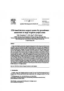
SO3 formation. Reduction furnace is used to minimize N Ox formation. N H3 rich sour water stripper gas along with required amount of air and fuel is fed to the burner to destroy N H3 to N2 . The hot gas is routed to the incinerator. Figure 1, shows the schematic representation of the incinerator in SRU. The hot flue gas from thermal oxidizer mixing chamber is passed through incinerator waste heat boiler to recover heat from the gas. Steam is generated. The flue gas from incinerator waste heat boiler at 325o C is discharged to the incinerator stack. The stack height of 80 meters is set to ensure dispersion of SO2 and to meet ground level concentration limits. Besides the oxidation of hydrocarbons to carbon dioxide and water, other oxidation reactions in the incinerator are as follows: H2 S + 3/2O2 −→ SO2 + H2 O 2COS + 3O2 −→ 2CO2 + 2SO2 CO + O2 −→ CO2 CS2 + 3O2 −→ 2SO2 + CO2 Sn + nO2 −→ nSO2 The incinerator effluent temperature controls the flow rate of fuel gas and it is maintained at desired operating temperature of ∼ 761oC. The incinerator is refractory lined with an external thermal shroud to control the shell temperature. Skin thermocouples are provided to monitor the shell temperature. The shell temperature is maintained between 149 to 350o C.The incinerator air blower is designed to ensure a minimum of 2 percent excess O2 in the flue gas at the stack and flue gas temperature of ∼ 761o C from the incinerator. Ambient air is drawn through the inlet filter to remove solid debris and to protect against water during heavy rainfall. The reaction in the reduction furnace is as follows: 2N H3 + 3/2O2 −→ N2 + 3H2 O The destruction of ammonia to nitrogen is ensured by adjusting air and fuel flow. Excess air causes formation of N Ox . The combustion air to the reduction furnace is drawn from the same incinerator air blower. The hot gas from the
reduction furnace is routed to the incinerator. The hot flue gas from incinerator is cooled by incinerator waste heat boiler. Incinerator WHB is used to recover heat from the flue gas and to generate MP steam. The flue gas at ∼ 325o C is vented to the atmosphere through the vent stack. SO2 , O2 , N Ox and CO analyzers are provided in the stack to measure the SO2 , O2 , N Ox and CO in the effluent gas.
Fig. 1.
Schematic Representation of the Incinerator
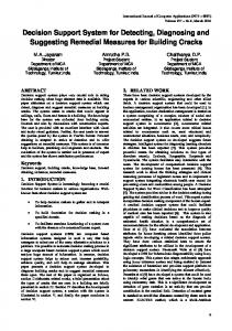
Suppose we know an input output relationship as described in equation (1). The inverse model is a function that produces the vector x for an input vector d. Equation (2) is the inverse model of equation (1). In an inverse plant model we construct a neural network approximation of f −1 (·) by using the data procured from the actual plant. The inverse plant model is shown in Figure 2.
Fig. 2.
II. RELATED WORK In 1973, studies were initiated to determine if it was necessary for the incinerator to consume large volumes of fuel gas to assure protection of the environment. Many laboratory and field investigations were carried out by Western Research on the optimal use of fuel gas in incinerators. The result of these studies are shown in previous works [1] - [3]. From these studies it was concluded that for a given incinerator there exists certain operating condition which requires minimum fuel consumption and yet provide satisfactory oxidization of harmful sulfur compounds. It was also found out in the studies that up to 40 percent of the fuel gas could be saved by operating the incinerators in these optimal operating range. There exists different works which propose different methodologies and techniques for increasing the efficiency of incinerators by use of effective catalysts [4], modified design for tail gas cleanup process for Claus process [5][6]. Recently artificial neural networks has been found to be very promising for adaptive control of nonlinear systems. The ability of neural networks to model arbitrary nonlinear functions and their inverses is shown in [7] - [12]. The generalizing capability of artificial neural networks avoids the requirement of a true analytical inverse [9] - [11]. Various algorithms have been used for training neural networks and Levenberg Marquardt algorithm is found to be very efficient algorithm. It is considered to be the combination of steepest descent and the Gauss Newton method [13]. Levenberg Marquardt is a standard iterative technique for non linear least squares problems [14][15]. III. ARCHITECTURE Perceptron is one of the simplest forms of artificial neuron used in artificial neural networks. Perceptron is built around McCulloch Pitts model of neuron. An input vector is given into the perceptron which is multiplied with the weight vector and linearly combined with the bias and is applied to the thresholding function which determines whether the output of the neuron. The model of a perceptron is shown in figure 3.
Block Diagram of Inverse Plant Model
d = f (x) x=f
−1
(d)
(1) (2)
This paper is organized as follows: In Section II, the related work is discussed. The Neural network models and architectures are discussed in Section III. Section IV gives the problem definition and Section V discusses about the proposed methodology including preparation of training data and training the ANN. The performance analysis is discussed in Section VI. Conclusion and the further possible research directions are discussed in section VII.
Fig. 3.
Representation of Perceptron
v = Σm i=1 wi xi + b
(3)
y = ϕ(v)
(4)
Where xi is the ith input and wi is the ith weight and b is the bias. v is the output of the linear combiner. ϕ(.) is the activation function. A single layer perceptron is an artificial neural network made of single layer of neurons. To overcome some practical limitations another model known as the multilayer perceptron is used which has an input layers, n number of hidden layers and an output layer. Figure 4, shows a structure of a multilayer perceptron. In this paper we used a multilayer perceptron to model the inverse plant.
Fig. 4.
approximation is used for the updation which is shown by the equation: Xk+1 = Xk [J T J + I]1 J T e
(7)
When the current value of the solution is not at all close to the correct solution, the Levenberg Marquardt algorithm acts like steepest descent method. When the current value of the solution is close to the correct one, the Levenberg Marquardt algorithm acts more like Gauss Newtons method. Thus the behavior of Levenberg Marquardt algorithm depends on the type of solution.The parameters of three layer perceptron artificial neural network developed for this project is shown in Figure 5.
Multilayer Perceptron
The initial weights for the model were found out by performing different runs using Bayesian regulation backpropagation. These initial weights obtained by the trial and error method are provided to the Levenberg Marquard algorithm . For training a neural network, Levenberg Marquardt (LM) algorithm is considered to be one of the best. This algorithm identifies the minimum of a function that is specified as the sum of squares of nonlinear functions. The combination of steepest descent and the Gauss Newton method is considered to be the Levenberg Marquardt algorithm. In this algorithm, the calculation of Hessian matrix is not required. Although in the case of Gauss Newton method the Hessian matrix is calculated. The Hessian matrix is approximated as the square of the Jacobian matrix which is given by the equation: T
H=J J
(5)
The gradient of the error function is given by the equation: g = JT e
(6)
Here J is the Jacobian matrix that contains first derivatives of the network errors with respect to the weights and biases and e is a vector of network errors. The standard backpropagation algorithm can be used for computing Jacobian matrix, instead of computing the Hessian matrix. Computation of Jacobian matrix using backpropagation is much more simpler. This
Fig. 5.
Parameters used in the model
IV. PROBLEM DEFINITION The waste gases stream from a modified Claus Sulfur Recovery Unit (SRU) contains a number of sulfur compounds that cannot be directly released into the atmosphere environment. The usual method of destroying these compounds is incineration. Since the concentration of combustible compounds in waste gas are too low to support combustion alone, it is necessary to add fuel gas to the incinerator to attain a temperature necessary for the oxidation of the compounds. The fuel gas being a costly resource needs to be optimally used to maximize the profits of the organization. Certain studies have shown that optimal incinerator control can lead upto 40 percent savings on fuel gas [1] thus decision support system is required to optimize the use of fuel gas and increase the efficiency of
the incineration process. The output of the incinerator depends upon the various factors such as oxygen concentration, air flow rate, fuel gas flow rate etc. Thus for the optimal control of the incinerator, an inverse plant is modeled with the help of neural network. V. METHODOLOGY The Following steps have been proposed to formulate the above said problem: 1) Data points of modified Claus plant tail gas incinerator were collected. 2) The Data points collected were plotted to visually understand the data. 3) The optimal operating range of modified Claus plant tail gas incinerator was identified. 4) A training data set was prepared over different optimal operating ranges of the incinerator. 5) MLPNN can be used to create a model which predicts the input parameters for optimal operation of the incinerator to meet the expected output. System can be simulated with the help of MATLAB/ SIMULINK. 6) Building a Multilayer Perceptron Neural Network where the operator enters the required plant output and the model predicts the input to the plant to meet the expected output. 7) The error histogram of the model is obtained to analyze the accuracy of the predictions. 8) The regression plot of the model is analyzed to understand the system performance.
B. Neural Network Model The proposed artificial neural network model have been simulated using neural networks toolbox in MATLAB. The model takes four inputs Vent O2 concentration, SO2 concentration, Temperature to be maintained in the incinerator, total flow rate of tail gas input into the incinerator. The Outputs of the network are control parameters of the process they are Fuel gas flowrate, Air flowrate and Oxygen concentration in the input air. The developed model is shown in figure 7. Figure 8, shows the GUI where the operator enters the required plant output and the model predicts the input to the plant to meet the expected output.
Fig. 7.
Inverse Plant Model
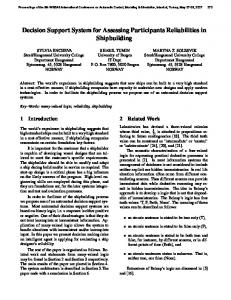
A. Preperation of Training Data Using a simulator data points of modified Claus plant tail gas incinerator were collected. These data points where graphically represented to understand the data. Figure 6, shows the relationship between the adiabatic stack temperature and fuel gas consumption. From figure 6, it is observed that the the curve is parabolic in nature. The curve shows that for optimal operation of the incinerator (less fuel more temperature) the data points should lie to the right of the curve.
Fig. 8.
GUI of the developed application
C. Training of Neural Network
Fig. 6.
Critical curve for incinerator operation
Many training algorithms have been developed for training of neural networks. All the training algorithm play a relevant and crucial role for the convergence of any perticular problem. In this paper, Levenberg Marquardt Algorithm is used for training our multilayer perceptron. The Levenberg Marquardt algorithm was developed by Kenneth Levenberg and Donald Marquardt. The Levenberg Marquardt method is a iterative technique used to solve nonlinear least squares problems and minimizes a nonlinear function. When the function is non linear in the parameters nonlinear least squares problem
is occurred. The Levenberg Marquardt method involve an iterative improvement to parameter values. Thus the sum of the squares of the errors between the function and the measured data points is reduced. The Levenberg Marquardt is a curve fitting method, which is actually a combination of two methods. It combines the gradient descent method and the Gauss Newton method. The fast convergence of Gauss Newton algorithm is combined with the stability of gradient descent algorithm. In gradient descent method, the parameters are updated to reduce the sum of the squared errors. The updation of the parameters is done in the direction of the greatest reduction of the least squares objective. In Gauss Newton method, the least squares function is assumed to be locally quadratic and the minimum of the quadratic is obtained. This assumption is made to reduce the sum of the squared errors. When the parameters are far from their optimal value the Levenberg Marquardt method behaves as gradient descent method. When the parameters are close to their optimal value the Levenberg Marquardt method behaves as Gauss Newton method. This algorithm is better and simpler than Gauss Newton, as the computation of hessian matrix is not required. It can solve the problems with error surface more than the quadratic approximation. Levenberg algorithm is superior to gradient decent algorithm as it converges the solution faster. The flow chart of the Levenberg Marquardt algorithm is shown in figure 9.
Fig. 9.
Levenberg Marquardt algorithm
observed that model has fit the data well as as all the points lie on the line inclined line.
The training process using Levenberg Marquardt algorithm is as follows: 1) The initial weights are randomly generated to evaluate the Mean Square Error. 2) Use Weight updation formula to update and adjust the weights. 3) With the help new updated weights, again evaluate the Mean Square Error. 4) Due to weight updation, if the Mean Square Error is increased, reset the weight vectors and increase the coefficient by some factor. Repeat weight updation as per step 2. 5) Due to weight updation, if the Mean Square Error is decreased, accept the new weight vector and decrease the coefficient by the same factor as in step 4. 6) Repeat the same procedure from step 2 with new updated weights after every iteration until the current total error is smaller than the threshold limit value. VI. PERFORMANCE ANALYSIS A neural network was modeled to predict the input parameters for modified Claus plant tail gas incinerator. The predicted parameters are Fuel gas flowrate, Air flowrate and Oxygen concentration in the input air. Figure 10 shows the error histogram of the trained model. From the error histogram it can be the error range in readings are between -6.1 and 3.65. Figure 11 shows the regression plot. It can be
Fig. 10.
Error histogram
[9] M.A. Hussain, L.S. Kershenbaum, Implementation of an Inverse-ModelBased Control Strategy Using Neural Networks on a Partially Simulated Exothermic Reactor, ELSEVIER Chemical Engineering Research and Design, Volume 78, Issue 2, March 2000, Pages 299311. [10] D.H. Rao, M.M Gupta and H.C Wood, Adaptive Inverse Control of Nonlinear Systems Using Dynamic Neural Networks, Intelligent System Research Laboratory, College of Engineering University, Saskatoon, Canada. [11] Jaroslava ilkov, Jaroslav Timko, Peter Girovsk, Nonlinear System Control Using Neural Networks, Department of Electrical Drives and Mechatronics Technical University of Koice Letn, Slovak Republic, 2006. [12] Haider A. F. Almurib, Direct Neural Network Control via Inverse Modelling, Department of Electrical and Electronic Engineering, The University of Nottingham Malaysia Campus Semenyih, 43500. [13] Manolis I. A. Lourakis, A Brief Description of the Levenberg-Marquardt Algorithm, Institute of Computer Science Foundation for Research and Technology - Hellas (FORTH), February 11, 2005. [14] Henri P. Gavin, The Levenberg-Marquardt Method for Nonlinear Least Squares Curve-tting Problems, Department of Civil and Environmental Engineering Duke University October 9, 2013. [15] Vijayashree, Training the Neural Network using Levenberg-Marquardts Algorithm to Optimize the Evacuation Time in an Automotive Vacuum Pump, International Journal of Advanced Research in Engineering and Technology (IJARET), April 3, 2013
Fig. 11.
Regression plot
VII. CONCLUSIONS In this paper, a Neural Network approach is shown for for the optimal incinerator control. The main contribution of this paper is to propose a decision support system by using an inverse plant model. The proposed model is built in MATLAB Simulink environment. It has been found that the model is able to successfully approximate the training data and generate the inputs for the plant for its optimal operation. The system can be extended by means of an Expert system so as to help the operator to make better decisions for optimal overall plant control. R EFERENCES [1] Harold G. Paskall and John A.Sames, Sulfur Recovery, 14th Edition. [2] R.K. Kert, H.G. Paskall and L.C. Biswanger, Sulphur Plant Waste Gases- Incineration Kinetics and Fuel Consumption, Energy Processing, Canada, March-April, 32-40, 1976. [3] Western Research and Development Ltd., A Study Of Incineration of Sulphur Plant Waste Gases, Report TS-DS-1-74 to the Government of the Province Of Alberta, Department of the Environment, May, 197). [4] Christophe Ndez, Jean-Louis Ray, A new Claus Catalyst to Reduce Atmospheric Pollution, ELSEVIER Catalysis Today, Volume 27, Issues 12, 29 January 1996, Pages 4953, 1st World Conference Environmental Catalysis For a Better World and Life. [5] Nicuor Vatachi, Modified Claus Process Applied To Natural Gas For Sulfur Recovery, Dunrea de Jos University of Galati, 2009, ISSN 12214558. [6] Yasser F. Al Wahedi, Optimization of Temperature Swing Adsorption Systems for the Purpose of Claus Tail Gas Clean Up, Master of science thesis submitted to the faculty of the graduate school of the University of Minnesota, June 2012. [7] K.J.Hunt, D.Sbarbaro, Neural Networks for Nonlinear Internal Model Control, In IEEE Proceedings of Control Theory and Applications, Volume:138, Issue: 5. [8] B.Widrow, M.Bilello, Adaptive inverse control, Intelligent Control, In Proceedings of the IEEE International Symposium on 25-27 Aug 1993.