Nov 20, 2012 - used to arrange for EIT [20] to generate large Kerr non- linearities. ..... [27] Michael Nielsen and Isaac Chuang, Quantum Computa- tion and ...
Nonlinear Optics Quantum Computing with Circuit-QED Prabin Adhikari1 , Mohammad Hafezi1,2 , J.M. Taylor1,2 1
2
Joint Quantum Institute, University of Maryland, College Park and National Institute of Standards and Technology, Gaithersburg, Maryland
PACS numbers: 03.67.Lx, 84.40.Dc, 85.25.Cp
(a)
(b)
φx
Circuit Model
φx
φ!x
Cr
L1
Lr
φ!x
Qubit
Resonator
(d) SLOW
Time [AU]
(c) Time [AU]
Linear optics quantum computing (LOQC) has proven to be one of the conceptually simplest approaches to building novel quantum states and proving the possibility of quantum information processing. This approach relies on the robustness of linear optical elements, but implicitly requires an optical nonlinearity [1–4]. Unfortunately, progress towards larger scale systems remains challenging due to the limits to optical nonlinearities, such as the measurement of single photons [5, 6]. In this letter we suggest recent advances in circuitQED in which optical and atomic-like systems in the microwave domain are explored for their novel quantum properties, provides a new paradigm for quantum computing with photons [7–9], which, in contrast to LOQC, is deterministic. Specifically, using superconducting nonlinearities in the form of Josephson junctions and the related quantum devices such as flux and phase qubits [10, 11], key elements of our approach have been realized: the creation of microwave photon Fock states [9, 12–14], controllable beam splitters [9, 15], and single microwave photon detection [16, 17]. In many cases, the photons stored in a transmission line-based resonator or inductor-capacitor resonator have much better coherence times than the attached superconducting qubits [18, 21, 22]. This suggests that the main impediment to photon based quantum computing is the realization of appropriate photon nonlinearities to enable two-qubit gates like two-photon phase gates, which are sufficient for universal quantum computation [1, 23]. The key element of a two-photon phase gate is a twophoton nonlinear phase shifter. It imparts a π phase on any state consisting of two photons, while leaving single photon and vacuum states unaffected. A deterministic approach to achieve such photon nonlinearity is based on the Kerr effect [18, 19, 24, 25]. In the context of circuit-QED, in Ref.[19], a four level N scheme using a coplanar waveguide resonator and a Cooper pair box is used to arrange for EIT [20] to generate large Kerr nonlinearities. In this Letter we take a different approach to photon nonlinearity. We explore the possibility of using a dc SQUID [26] to implement a nonlinear coupling between qubit and resonator, which, through an adia-
NL 50/50
φx Energy [AU]
arXiv:1208.2960v2 [quant-ph] 20 Nov 2012
One approach to quantum information processing is to use photons as quantum bits and rely on linear optical elements for most operations. However, some optical nonlinearity is necessary to enable universal quantum computing [1–4]. Here, we suggest a circuit-QED approach to nonlinear optics quantum computing in the microwave regime, including a deterministic two-photon phase gate. Our specific example uses a hybrid quantum system comprising a LC resonator coupled to a superconducting flux qubit to implement a nonlinear coupling. Compared to the self-Kerr nonlinearity, we find that our approach has improved tolerance to noise in the qubit while maintaining fast operation.
NL 01 01 10 10
2 Photons 1 Photon
φx
50/50
Qubit 1
Position
01 10 01 10
Qubit 2
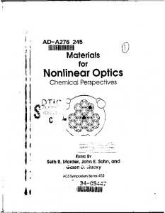
FIG. 1: (a) Implementation of a high-impedance coiled resonator (blue) coupled to a dc SQUID (red) with an inductive outer loop. The flux bias lines are in black. (b) A simple circuit model of our physical implementation. (c) Bottom: Energy levels of the coupled system with a sizeable two-photon coupling. Top: The suggested flux bias pulse φx to implement the nonlinear phase shift; a fast but adiabatic sweep and then a very slow variation of the pulse near the avoided crossing. (d) Use of two nonlinear phase shifters, combined with 50/50 beamsplitters, leads to a deterministic two photon phase gate using dual rail logic. The two photons in the dual rail basis |0iL |1iL = |01i1 |10i2 of the two qubits become bunched into a single mode after passing through the first beam splitter, and then receive a π phase from the nonlinear phase shifter. Storage cavities (not shown in (b)) are blue lines.
batic scheme, enables a high fidelity, deterministic twophoton nonlinear phase shift in the microwave domain. Along with the nonlinearity, we envision using dynamically controlled cavity coupling to implement a 50/50 beam splitter operation to construct a two-photon phase gate using so-called dual rail photon qubits [9, 27], in
2 which the logical basis {|0iL = |01i , |1iL = |10i} corresponds to the existence of a single photon in one of two resonator modes (Figure 1d). Our approach takes best advantage of the relatively long coherence times for microwave photons in resonators, and couples only virtually to superconducting quantum bit devices, minimizing noise and loss due to errors in such devices. When combined with the aforementioned techniques for Fock state generation and detection, along with dynamically controlled beam splitters, this provides the final element for nonlinear optics quantum computing in the microwave domain. We now outline our approach. We consider photons stored in a high-impedance microwave resonator [28] coupled inductively with strength 0 < χ < 1 to a flux superconducting qubit (SQ) in a dc SQUID configuration (Figure 1a). The resonator loops around the dc SQUID which results in a nonlinear cosine dependent interaction between the resonator and qubit. In this configuration, we get an effective coupling of the form V ∼ EJ cos(φˆ + φ0x ) cos φˆr , where an external flux φ0x ≡ 2πχΦ0x /Φ0 is applied to the resonator which consequently threads the smaller loop of the dc SQUID, Φ0 being the superconducting flux quantum. The qubit phase variable and the resonator flux are denoted by φˆ and ˆ r /Φ0 respectively. For φ0x ∼ π/2, we see imφˆr = 2π Φ mediately a nonlinear coupling between the qubit and resonator: V ∼ EJ φˆφˆ2r , where two resonator photons can be annihilated to produce one qubit excitation, analogous to parametric up conversion in χ(2) systems. This causes the two-photon state of the resonator to couple to the first excited state of the SQ with strength g2 (Figure 1c). In essence, in this region, the two-photon state with detuning δ from the qubit, becomes slightly qubit-like and acquires some nonlinearity. However, the single-photon state, inspite of its coupling to the first excitation of the SQ with strength g1 , remains mostly photon-like because it is far detuned by ∆ from this qubit excitation. At the end of the procedure, this leads to an additional phase for the two-photon initial state. The coupling of the twophoton state to other modes arises via linear coupling at O(g1 ) and is assumed to be far detuned. The noise in the SQ, with a decay rate γ of its first excited state, may slightly limit our nonlinear phase shift operation. Although the overall system will mostly be in the photon-like regime with decay rate κ, there will be an additional probability for it to decay due to its coupling to the lossy qubit. In the limit where |δ| � |g2 | and |∆| � |g1 | with |∆| > |δ|, the two-photon nonlinearity goes like g22 /δ, and the two-photon state decays approximately at a rate γg12 /∆2 + γg22 /δ 2 . Thus, the losses due to the qubit go like γ/δ provided we allow g1 to become close to g2 , which is possible by controlling φ0x . Hence, at large detuning, we will then be limited only by κ. In contrast, a Kerr nonlinearity scales like g14 /δ 3 and the noise scales like γg12 /δ 2 , leading to more loss due to the qubit for large detuning. We now examine a detailed model to support these
qualitative arguments. In our case, the second resonator is not coupled to a SQ and is not shown; we focus on the dynamics of the first resonator, which is coupled. The quantum Hamiltonian of the system is H = T + V [29]. qˆr2 qˆ2 χ + − qˆqˆr , (1) 2Cr 2CJ 2Cr � �2 ˆ2 Φ0 φr ˆ V = − EJ [cos(φˆ + χφˆr + φ0x ) + cos φ] 2π 2Lr EL ˆ + (φ + φx )2 . (2) 2 T =
In addition to φ0x , an external flux bias φx = 2πΦx /Φ0 is applied to the outer inductor loop attached to the squid. The canonical coordinates of the qubit satisfy ˆ N ˆ ] = i, where N ˆ = qˆ(2e)−1 is the number of Cooper [φ, ˆ r and qˆr reppairs in the junctions. The operators Φ resent quantum fluctuations in flux and charge of the ˆ r , qˆr ] = i~, and χ is the fraction resonator satisfying [Φ ˆ of the flux Φr threading the squid loop. This inductive coupling causes the effective capacitances of the resonator and qubit to be modified, and we denote these modified values by Cr and CJ respectively. EJ is the Josephson energy of each junction, while EL = Φ20 /(4π 2 L1 ) represents the inductive energy of the qubit due to the bigger loop. We can also define an effective charging energy of the junction to be EC = (2e)2 CJ−1 . We intro0 duce another p dimensionless parameter µ = 2πΦ−1 0 Φr , 0 Lr ω~/2 is the width of quantum flucwhere Φr = tuations in the resonator flux. In terms of the quantum of conductance G0 = 2e2 /h and the characteristic impedance of the resonator Z = (Lr /Cr )1/2 , we can write √ µ = 2πG0 Z. Since µ � 1, we can expand V in powers of χφˆr ∝ µ. Performing the expansion to second order, we get H = Hr + Hq + VI with ˆ2 qˆr2 Φ + r (3) 2Cr 2Lr � � � � qˆ2 φ0 φ0 EL ˆ = − 2EJ cos x cos φˆ + x + ( φ + φx ) 2 2CJ 2 2 2 χˆ q qˆr χφˆ2r cos(φˆ + φ0x )] − = χEJ [φˆr sin(φˆ + φ0x ) + 2 2Cr
Hr = Hq VI
corresponding to the resonator, qubit, and interaction terms respectively. We remark that asymmetry in the two Josephson junctions leads to additional terms, but our general linearization approach described below remains valid, and provides qualitatively similar results. The equations (3) can be used to solve this system numerically. However, in the regime where EL � EJ we can get some analytical results. First, we linearize the potential in (2) around the classical values of the resonator reduced flux φcl and the qubit phase βcl = −φx + f , with quantum fluctuations ϕˆr and ϕˆ around them. Any nonlinearity can then be treated as a perturbation. Note the
3 following functions of φx and φ0x .
We neglect all higher order nonlinear terms and only consider the perturbative χ(2) type nonlinearity given by,
EJ Lr χ sin(φx − φ0x ) 2 Φ0 /(2π)2 + EJ Lr χ2 cos(φx EJ [sin φx + sin(φx − φ0x
, − φ0x ) − χφcl )] f ≡ , EL + EJ [cos φx + cos(φx − φ0x − χφcl )] r ≡ sin βcl ; s ≡ sin [βcl + φ0x + χφcl ] , t ≡ cos βcl ; u ≡ cos [βcl + φ0x + χφcl ] .
φcl =
(4) (5) (6) (7)
−1 ˜ −1 With the effective inductance of resonator L r = Lr + ˆr = Φ0 /(2π)ϕˆr , the resonator and (2π/Φ0 )2 EJ χ2 u and Φ qubit Hamiltonians can now be written as
Hr =
qˆ2 Φˆ2 EL + EJ (t + u) 2 qˆr2 + r ; Hq = + ϕˆ (8) ˜r 2Cr 2CJ 2 2L
−1/2 ˜ with and ωq = p respective frequencies ω = (Lr Cr ) ωC [ωL + ωJ (t + u)]. We see immediately that changing the external fluxes changes these frequencies, and hence, the qubit-resonator detuning ∆ = ωq − ω. Introducing creation and annihilation operators for the resonator and qubit satisfying [ˆ a, a ˆ† ] = 1 = [ˆb, ˆb† ] with r r ωC ˆ ˆ† ωq ˆ ˆ† ˆ ϕˆ = (b + b ); N = −i (b − b ), (9) 2ωq 2ωC s s ˜ r ω~ L ~ † Φˆr = (ˆ a+a ˆ ); qˆr = −i (ˆ a−a ˆ† ). ˜rω 2 2L
the resonator and qubit Hamiltonians become Hr = ωˆ a† a ˆ †ˆ ˆ and Hq = ωq b b. When the qubit is not linearized as in (3), the potential energy terms can be written as V1 = η1 (ˆ a+a ˆ† ) sin(φˆ + φ0x ), V2 = η2 (ˆ a+a ˆ† )2 cos(φˆ + φ0 ), x
V3
ˆ, = iη3 (ˆ a−a ˆ )N †
(10) (11) (12)
with coupling coefficients η1 = χEJ µ, η2 = η12 /(2EJ ), and η3 = (η1 ~ω)/(2EJ ). The potential that is of relevance is V2 from which the nonlinear coupling term g2 is seen to be √ g2 = 2η2 h0q | cos(φˆ + φ0x ) |1q i , (13) where the matrix element is between the ground and first excited qubit states. The size of g2 is important for the success of the nonlinear phase shift protocol. For a given value of η1 , the Josephson energy EJ of each junction cannot be made too large as this will suppress η2 and g2 . Hence, it is desirable to operate the qubit in the flux regime where EJ ≤ 10EC . The linear coupling coefficient η1 depends on the characteristic impedance Z of the LC circuit implicit in the parameter µ. Therefore, we have to implement a resonator with high Z to make g2 larger. After linearization, the flux dependent linear Hamiltonian of the system can be written as HL = Hr + Hq −
χ qˆqˆr + χEJ u ϕˆr ϕ. ˆ 2Cr
(14)
V2 = −EJ χ2 s/2 ϕˆ ϕˆ2r .
(15)
We can make the rotating wave approximation and write HL in terms of creation and annihilation operators as HL = ωˆ a† a ˆ + ωq ˆb†ˆb + g1 (ˆ aˆb† + a ˆ†ˆb), where the linear coupling g1 is given by r r ωC ωq g1 = η1 u − η3 . 2ωq 2ωC
(16)
(17)
To diagonalize HL we define new operators cˆ and dˆ as ˆ ˆb = µ2 cˆ + ν2 d, ˆ a ˆ = µ1 cˆ + ν1 d;
(18)
ˆ dˆ† ] and [ˆ ˆ This such that [ˆ c, cˆ† ] = 1 = [d, c, dˆ† ] = 0 = [ˆ c, d]. requires the conditions |µ1 |2 + |ν1 |2 = 1 = |µ2 |2 + |ν2 |2 ; µ1 µ?2 + ν1 ν2? = 0. (19) The parametrization µ1 = cos θ, ν1 = − sin θ, µ2 = sin θ, ν2 = cos θ satisfies the constraints (19). Substituting the relations (18) into HL and setting the diagonal terms to zero, we get a normal mode Hamiltonian H = Ω1 cˆ† cˆ �+ � pN Ω2 dˆ† dˆ with energies Ω1,2 = ω+∆/2 1 ∓ 1 + 4g12 /∆2 . We assume the detuning ∆ > 0. The bare basis states of the resonator-qubit system will be denoted by |ni ⊗ |qi ≡ |n qi, where the first and second labels refer to the quantum numbers of the resonator and qubit respectively. The relevant eigenstates of the Hamiltonian in the new † basis are number excitations of the � operators cˆ cˆ and †ˆ ˆ ¯ ¯ d d. Denoting these kets as C D , we can write down three important eigenstates with energies Ω1 , Ω2 , and 2Ω1 . They are |¯1¯0i = cos θ |10i + sin θ |01i , (20) |¯0¯1i = − sin θ |10i + cos θ |01i , √ ¯ = cos2 θ |20i + 2 cos θ sin θ |11i + sin2 θ |02i . |2¯0i The parameter θ satisfies tan 2θ = −2g1 ∆−1 . For ∆ � |g1 |, |¯1¯0i → |10i, |¯0¯1i → |01i, |¯2¯0i → |20i, Ω1 → ω, and Ω2 → ωq . The nonlinearity in our model couples the states |¯ 2¯ 0i and |¯0¯1i leading to a sizeable avoided crossing in Figure 1c between the two-photon and qubit levels. In terms of the normal mode operators V2 = η20 [cos2 θ sin θˆ c†2 cˆ − cos3 θˆ c†2 dˆ − 2 cos θ sin2 θˆ c† cˆdˆ† ˆ + HC, +2 cos2 θ sin θˆ c† dˆ† dˆ + sin3 θˆ cdˆ†2 − sin2 θ cos θdˆ†2 d] √ where η20 = η2 s/ 2. Then the overall Hamiltonian of interest becomes H = Ω1 cˆ† cˆ + Ω2 dˆ† dˆ + V2 . Working in the truncated subspace spanned by the states {|0i ≡ |¯0¯0i , |ai ≡ |¯1¯0i , |bi ≡ |¯2¯0i , |ci ≡ |¯ 0¯ 1i},
4
(22)
where we have associated the nonlinear coupling g2 with η20 r2 . The nonlinear phase-shift protocol requires initializing the system in the states |10i ≈ |¯ 1¯ 0i and |20i ≈ |¯2¯0i with errors that go like g12 /∆2 . Then the external fluxes φx and φ0x are varied adiabatically so that the state |¯2¯0i becomes slightly qubit-like, mostly because of |11i. After accumulating the desired phase, the process is reversed to retrieve the photons. For some integer n, we require for a Rτ total time τg , 0 g Nl (t)dt = (2n+1)π. The final outcome is then √13 (|00i + |10i + |20i) → √13 (|00i + |10i − |20i). In addition to our analytical model, we also diagonalize the Hamiltonian of the system numerically by working in the tensor product space H = Hr ⊗ Hq of the resonator and qubit using the Hamiltonian in (3). The basis states in the resonator space are the number excitations |ni. The qubit space is written in the basis of qubit wavefunctions ψq (φ) = hφ| qi. We let ~ = 1 and choose ωC /(2π) = 1 GHz, ωJ /(2π) = 5 GHz, ωL = 3ωJ , and ω/(2π) = 2.225 GHz. The characteristic impedance Z ≈ 449 Ω. We choose a χ = 0.17, representing an easily achievable mutual inductance, from which follow η1 /(2π) = 400 MHz, η2 /(2π) = 16 MHz, and η3 /(2π) = 89 MHz. Now we discuss the effect of loss on our gate. Since throughout the operation of the gate the system remains photon-like, loss is dominated by the cavity decay at a rate κ. For the photon-like state |¯ 2¯ 0i, there are two other decay channels due to the cavity-qubit coupling. The linear coupling g1 in the limit ∆ � |g1 | leads to γ1 ≡ γg12 /∆2 = γg12 /(δ + ω)2 . Similarly the nonlinear coupling leads to γ2 ≡ γg22 /δ 2 for |δ| � |g2 |. Including the cavity decay rate κ, the total decay rate of the two-photon-like state becomes Γ(δ) = κ + γ1 + γ2 . Assuming g2 is time independent for simplicity, adia˙ 2 (δ 2 + 4g 2 )−3 � 1 . We can set this baticity requires g22 |δ| 2 2 equal to some � � 1 and solve for Z 1 δm |g2 | τh (δm ) = − dδ, (23) � δi (δ 2 + 4g22 ) 23 which is the time taken to go from |δi | � |g2 | at t = 0 to smaller values of detuning with a minimum δm . The
0.5
01 b
6
φ!x /π
g1
20
t t
0
11
g2
30
tq
10
Resonator Ground Qubit Ground
(c) 25 20 15 10 5 0 "5
�0.5 0 �1
+
�0.5
�1.5
+
�1 1 �1
!
δ (GHz)
1
�0.5
0
0.5
1
8
φ!x /π
0.5
4.6 4.4 4.2 4.0 3.8 3.6 3.4
7 6
0
5
+
�0.5
!
! 0.2
0.4
0.6
0.8
1.0
�1
φx /π
4 3 2
+
10 MHz
�1
0.0
�2 9
!
�0.5
0
φx /π
1 0.5
1
|g2 | (MHz)
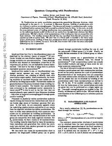
FIG. 2: (a) Schematic of the system bare energy levels and couplings. (b) Contour plot of detuning δ and |g2 | with the on and off points marked in green and red. The on point is chosen such that the g2 is maximized. (c) Top: The coupling g1 /10 and g2 , with the on and off fluxes shown. Bottom: The bare frequencies 2ω/(2π) and ωq /(2π) obtained from the analytical model (dashed) and numerical results (solid). The overall qubit-resonator interaction leads to a splitting of approximately 10 MHz. (a)
(b) 0.100 0.050
10!5 10!6 10!7
Ls
g2 g2 (η 0 r2 )2 ≡ − 20 ≈ − 2 . Nl = − 2 0 δ δ δ
(b) 02
2Ω , Ωq !2 Π GHz" g1!10 "MHz#, g2 "MHz#
We can use this Hamiltonian to calculate the twophoton nonlinearity Nl . For |δ 0 | ≡ |Ω2 − 2Ω1 | � |η20 r2 |, we have
(a)
Ld
we write the Hamiltonian as H = H0 + V where H0 = Ω1 |ai ha| + 2Ω1 |bi hb| + Ω2 |ci hc| and the coupling V = λ1 (|ai√ hb| + |bi ha|) + λ2 (|bi hc| + |ci hb|). The √ parameters λ1 = 2η20 cos2 θ sin θ ≡ r1 η20 and λ2 = − 2η20 cos3 θ ≡ r2 η20 . We can adiabatically eliminate the state |ai to find an effective Hamiltonian � � � � r2 η 02 r2 η 02 He = Ω1 − 1 2 |ai ha| + 2Ω1 + 1 2 |bi hb| Ω1 Ω1 0 + Ω2 |ci hc| + r2 η2 (|bi hc| + |ci hb|). (21)
10!8
0.010 0.005
0.001 5 " 10!4
10!9 !0.5
!0.4
!0.3 !0.2 ∆m !GHz"
!0.5
!0.1
!0.4
!0.3 !0.2 ∆m !GHz"
!0.1
FIG. 3: (a) A plot of the dimensionless dynamic loss Ld for κ = 1 KHz, γ = 100κ and �2 = 0.01. The detuning −536 MHz ≤ δm ≤ −41 MHz. (b) The static loss Ls in purple, and the static loss without the effect of the cavity decay rate κ in green.
total dynamic loss during the process is given by 2 Ld (δm ) = �
Z
δi
Γ(δ) δm
|g2 | (δ 2
3
+ 4g22 ) 2
dδ.
(24)
When the detuning is held at δm for a time τs = πδm /g22 , the static loss Ls (δm ) = τs Γ(δm ). Thus, " # � �2 κδm γδm g1 γ Ls (δm ) = π + + , (25) g22 (δm + ω)2 g2 δm and the total time of the protocol is τg = 2τh +τs . Assump ing δm � ω, Ls (δm ) is minimized when δm ≈ g2 γ/κ.
5 However, the on-off ratio of the photon nonlinearity goes like |δi /δm |, and a value of δm that makes this ratio at least a hundred is desirable. For δ ∼ ω, we can make g1 ≈ g2 so that Ls (δ) < κδ/g22 +2γ/δ. In this regime Ls is limited by κ, as can be verified from Figure 3b. Thus, we optimize our protocol so that the loss L = Ld + Ls � 1. We note that our protection is only against qubit noise and loss, and comes at the cost of increased reliance on the cavity quality factor. The protocol might also be limited by dephasing of the qubit due to flux noise [30–32]. The average slopes of the single and two-photon energy levels with respect to the reduced flux φx are approximately 50 MHz and 100 MHz respectively, while the slope of the qubit energy level is at most 1 GHz for the parameters chosen. However, the exact loss due to dephasing depends on the flux noise
amplitude [33, 34]. In conclusion, we have demonstrated that by appropriately tuning the two control fluxes, the nonlinear coupling enables a two-photon nonlinear phase shift operation with loss at large detuning limited only by the cavity quality factor. This is highly desirable compared to the self-Kerr nonlinearity which leads to more loss due to the qubit for large detunings. Furthermore, our approach may be adaptable to recent ultra-high quality factor resonators enabling nonlinear optics quantum computing in a fully engineered system [22]. The authors wish to thank E. Tiesinga, J. Aumentado, A. Blais, and S. Girvin for helpful discussions. This research was supported by the US Army Research Office MURI award W911NF0910406 and the NSF through the Physics Frontier Center at the Joint Quantum Institute.
[1] E. Knill, R. Laflamme, and G. J. Milburn, Nature 409, 46-52 (2001). [2] Pieter Kok et al., Rev. Mod. Phys. 79, 135174 (2007). [3] Michael A. Nielsen, Phys. Rev. Lett. 93, 040503 (2004). [4] Daniel E. Browne, Phys. Rev. Lett. 95, 010501 (2005). [5] G. S. Buller and R. J. Collins, Measurement Science and Technology, 21 (2010). [6] D. I. Schuster et al., Nature 445, 515-518 (2007). [7] A. Blais et al., Phys. Rev. A 69, 062320 (2004). [8] A. Wallraff et al., Nature 431, 162-167 (2004). [9] Eva Zakka-Bajjani et al., Nature Physics 7, 599-603 (2011). [10] John M. Martinis, arxiv:cond-mat/0402415v1[condmat.supr-con]. [11] Maxim Boissonneault, J. M. Gambetta, and A. Blais, arxiv1206.1296v1[quant-ph]. [12] C. Eichler et al., Phys. Rev. Lett. 106, 220503 (2011). [13] A. A. Houck et al., Nature 449, 328-331 (2007). [14] Max Hofheinz et al., Nature 454, 310-314 (2008). [15] Yanhong Xiao et al., Phys. Rev. Lett. 101, 043601 (2008). [16] B. R. Johnson et al., Nature Physics 6, 663-667 (2010). [17] G. Romero, J. J. Garc´ıa-Ripoll, and E. Solano, Phys. Rev. Lett. 102, 173602 (2009). [18] Yi Yin et al., Phys. Rev. A 85, 023826 (2012). [19] Stojan Rebi´c, Jason Twamley, Gerard J. Milburn, Phys. Rev. Lett. 103, 150503 (2009). [20] Michael Fleischhauer, Atac Imam˘ oglu, Jonathan P. Marangos, Rev. Mod. Phys. 77, 633 (2005). [21] Abdufarrukh A. Abdumalikov, Jr. et al., Phys. Rev. B 78, 180502(R) (2008). [22] Hanhee Paik et al., Phys. Rev. Lett. 107, 240501 (2011). [23] David P. DiVincenzo, Phys. Rev. A 51, 1015-1022 (1995). [24] Kae Nemoto and W. J. Munro, Phys. Rev. Lett. 93, 250502 (2004). [25] Io-Chun Hoi et al., arXiv:1207.1203v1[quant-ph]. [26] John Clarke and Alex I. Braginsky, The Squid HandBook: Applications of Squids and Squid Systems, (Wiley-VCH, 2007) Vol. 2. [27] Michael Nielsen and Isaac Chuang, Quantum Computation and Quantum Information (Cambridge University Press, 2000).
[28] J. D. Teufel et al., Nature 471, 204-208 (2011). [29] Michel H. Devoret, Les Houches Session LXIII, 351-386 (1995). [30] John M. Martinis et al., Phys. Rev. B 67, 094510 (2003). [31] Radoslaw C. Bialczak et al., Phys. Rev. Lett. 99, 187006 (2007). [32] K. Kakuyanagi et al., Phys. Rev. Lett. 98, 047004 (2007). [33] Matthias Steffen et al., Phys. Rev. Lett. 105, 100502 (2010). [34] S. M. Anton et al., Phys. Rev. B 85, 224505 (2012).