ABSTRACT: Vibro Replacement is a ground improvement technique commonly ... lation of gravel or stone columns leads to an improvement of the mechanical ...
Numerical Investigation of the Mechanical Behaviour of Vibro Replacement Stone Columns in Soft Soils T. Meier & E. Nacke & I. Herle1 W. Wehr2 1 2
Inst. of Geotechnical Engineering, Technische Universit¨at Dresden, Germany Keller Holding GmbH, Offenbach, Germany
ABSTRACT: Vibro Replacement is a ground improvement technique commonly used in practice. The installation of gravel or stone columns leads to an improvement of the mechanical properties of the subsoil in terms of bearing capacity and more important stiffness, thus settlements can be reduced. For the design of vibro replacement a procedure by Priebe is often employed in practice. It contains some major simplifications and assumptions, e.g. the soil surrounding the column behaves linear-elastically with Poisson’s ratio ν = 1/3 or the earth pressure coefficient after the installation process K = 1.0. By means of comprehensive laboratory tests and a finite element model using advanced hypoplastic constitutive equations, the mechanical behaviour of vibro replacement columns in soft soils was investigated. With the aid of such a model it is possible to analyse the simplifications of Priebe’s theoretical model mentioned above.
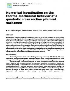
1 INTRODUCTION In this study the mechanical behaviour of so-called unit cells (Fig. 1) consisting of very soft soil and a granular replacement column supported by a rigid underlying stratum are investigated. Considering such unit cells with oedometric boundary conditions corresponds to an ”infinite” (large-area) grid of replacement columns.
area of the complete cell (soil plus column) and Ac is the area of the column. The design method by Priebe (Priebe 1995) is an analytical method based on the cylindrical cavity expansion problem in a linear-elastic half-space. It contains several major simplifications and assumptions: • Linear-elastic behaviour of the column and the soil.
Δrc rc
r
• Design charts are given only for one constant Poisson ratio ν = 1/3 of the soil to be improved. • Uniform radial strains εr = ∆rc /rc0 of the column due to loading (cylindrical cavity expansion).
Figure 1: Unit cell.
The design of a vibro replacement measure consists of the choice of the spacing, the diameter and the depth of the columns. In the following the spacing is expressed as the area ratio A/Ac , where A is the
• Earth pressure coefficient of the soft soil K = 1.0 due to the column installation process. The aim of the presented study is to compare improvement factors n (Eq. 1) obtained from this simple analytical model with those from finite element analyses using two advanced hypoplastic constitutive models.
n := where s0 simp
s0 simp
(1)
− settlement of untreated ground − settlement with replacement columns
Furthermore, the results of the finite element analyses allow an insight into deformations of the system column/soft soil due to loading. 2 CONSTITUTIVE MODELS Two hypoplastic constitutive equations were employed for the mathematical description of the mechanical behaviour of the soft soil to be improved and the granular material of the column. The main advantage of these equations is a clear distinction between material parameters (e.g. critical friction angle) and state variables (stress and density), i. e. for one set of material parameters, which are determined by means of standard laboratory tests on disturbed or remoulded samples, respectively, it is possible to simulate the mechanical behaviour of soils over a wide range of stress states and densities. In the following subsections the two constitutive models are briefly described with respect to the incorporated parameters. 2.1 Soft Soil For the description of the soft soil a model proposed by Maˇs´ın (Maˇs´ın 2005) was used. It contains five material parameters: • Critical friction angle ϕc : The critical friction angle ϕc determines the resistance of a soil subjected to monotonic shearing in critical state, i.e. when σ˙ = 0 and the volumetric strain rate ˙ = 0 hold. Drained or undrained triε˙v = tr(ε) axial tests, simple shear or direct shear tests on initially very loose specimens are appropriate for the determination of ϕc . • Compression and swelling index λ∗ and κ∗ of Butterfield’s compression law (Eq. 2) (Butterfield 1979) � � � 0� 1 + e0 p ∗ ln = λ · ln 0 (2) 1+e p0 where p0 = −tr(σ)/3 is the effective mean pressure and p00 together with the void ratio e0 define the normal consolidation line. Determined by means of isotropic or oedometric compression tests. In case of swelling λ∗ is replaced κ∗ . • N = ln (1 + e0 ), an expression for the reference void ratio e0 at isotropic effective stress
σii0 = −1 kPa of a normally consolidated sample, (OCR = 1.0) Determined by isotropic or approximated by oedometric compression tests. • Stiffness ratio r = Ki /Gi , where Ki is an incremental bulk modulus for isotropic compression and Gi is an incremental shear modulus for undrained shearing at the same isotropic stress state with OCR = 1.0. Determined by means of CU triaxial tests. For this numerical study the material parameters (Tab. 1) of a natural clay (CL, index properties cf. Tab. 2) were used. Table 1: Material parameters of the soft soil. ϕc λ∗ κ∗ N r 26.1◦ 0.086 0.018 0.9894 0.33 Table 2: Index properties of the soft soil (with ρs – grain density, wL/P – liquid/plastic limit, CC–clay content, IL–ignition loss). ρs wL wP CC IL 3 2.752 g/cm 43.4 % 20.9 % 50 % 3.1 % 2.2 Stone Column The column material was modeled using a hypoplastic equation for granular soils (Wolffersdorff 1996). It contains eight material parameters: • Critical friction angle ϕc (see above). • Limit void ratios at zero stress ed0 , ec0 , ei0 : ed0 = emin is a lower bound void ratio of a grain skeleton at zero pressure, ec0 = emax is the void ratio in the critical state at zero pressure. Both, emin and emax are determined through standard index tests (e.g. according to ASTM D4254 and D4253). ei0 is an upper bound void ratio of a simple grain skeleton at vanishing pressure (without macropores). ei0 ≈ 1.15emax and ed0 ≈ 0.6ec0 are simple estimates (Herle 1997) which have been used successfully for more than a decade. • Granulate hardness hs and exponent n: In the case of an isotropic compression of a very loose sample (e0 = emax ) the hypoplastic constitutive equation reduces to the compression law by Bauer � � �n � 3 · p0 e = e0 · exp − (3) hs where a reference pressure, the so-called granulate hardness hs , together with the exponent n govern the compression for an increasing effective mean pressure p0 .
• Exponents α and β: The exponent α controls the peak friction angle of the material, and hence also the dilatancy behaviour. The stiffness of a grain skeleton with e < ec can be adjusted via the exponent β.
• Stress State: bulk density of both materials γ = 18 kN/m3 , σv0 = γ · z, σr0 = K · σv0 • Density: Column e0 = 0.6, soft soil OCR = 1.05 (stress dependent void ratio e)
A comprehensive step-by-step description of the calibration procedure can be found in (Meier 2009). The parameters were calibrated from special laboratory tests with rockfill (d50 ≈ 15 mm, dmax = 40 mm, CU = 2.7, CC = 1.0, ρs = 2.77 g/cm3 ). The resulting parameters are given in Table 3. Figure 2 shows the comparison between oedometric compression tests and the corresponding results obtained by hypoplasticity. Table 3: Material parameters of the rockfill. ϕc hs n ed0 /ec0 /ei0 α β 40.7◦ 41 GPa 0.24 0.50/0.82/0.93 0.10 1.53
0.567
0.79
0.566
e0=0.795 hypo. lab.
0.78
0.565 e
e
0.563 0.562 0.561 0.560 0.559
Figure 3: Layout of the FE model.
0.77
0.564
0.76
With the aid of this model the influence of the following quantities on the improvement factor was studied:
0.75 e0=0.567 hypo. lab. 10
100 -σ’v / kPa
0.74 0.73 1000
10
100 -σ’v / kPa
1000
(a) (b) Figure 2: Oedometric compression tests on rockfill.
3 FINITE ELEMENT MODEL Figure 3 depicts a layout of the axisymmetric FE model. To allow for the influence of the geostatic stress state, which leads to an increase of stiffness of both materials with depth, a 5 m long column was modeled. It is assumed that the influence of the length of the column on the improvement factor is negligible, as has been shown numerically e.g. by (Borges and Domingues 2009). The analyses were performed with the FE code Tochnog (version 5.0) using evenly spaced first oder crossed triangle elements. The top nodes (”rigid plate”) were constrained to have all the same vertical displacement and the loading was done by a uniformly distributed load linearly increasing with time (mixed boundary conditions). In case of non-linear calculations both spatial and time discretisation can have a strong impact on the calculation results. Hence both were refined until no change in the results due to this refinement could be observed anymore. The initial conditions were:
• area ratio A/Ac • magnitude of superimposed load • initial stress state in terms of the earth pressure coefficient K = σr /σv (σr - radial and σv - vertical stress) • relative density of the column 4 RESULTS 4.1 Influence of Poisson’s Ratio As mentioned earlier, the design charts given by Priebe are based on calculations with Poisson’s ratio ν = 1/3 of the soft soil. To study the influence of this quantity on the improvement factor n = f (A/Ac ) the method was programmed and comparative calculations were carried out. The results are depicted in Figure 4. As can be clearly seen, the influence of ν on the improvement factor n is negligible. 4.2 Influence of the Load Magnitude Figure 5 shows the influence of the load magnitude on n as obtained from the Priebe method and from the finite element analyses. Both methods show a decrease of n with increasing load. The effect is more pronounced for small area ratios and in general in case
16 14 12 10
K=0.5 K=1.0
-1
K=2.0 -2 t/m
n
0
ν = 0.1 ν = 0.2 ν = 0.3 ν = 0.4 ν = 0.5 Es=0.6 MPa
8
-3
6 4
-4 Es=10 MPa
2 0
-5 1
2
3
4
5 A/Ac
6
7
8
9
0.0
0.5
1.0
1.5
2.0
K
Figure 4: Improvement factor n vs. area ratio A/Ac for different Poissons’ ratios ν and constrained moduli Es of the soft soil.
Figure 6: Distribution of the earth pressure coefficient K along the interface (cross symbols – initial values, boxes – after loading)
of the FE method. For loads p ≤ 125 kPa the Priebe method is conservative compared to the FE results.
the confining pressure on the column from the soft soil, the stiffer the system reacts to loading.
16
FE: p=125 kPa FE: p=250 kPa FE: p=500 kPa Priebe: p=125 kPa Priebe: p=250 kPa Priebe: p=500 kPa
14 12
8
n
n
10
6 4 2 0 1
2
3
4
5 A/Ac
6
7
8
9
Figure 5: Improvement factor n vs. area ratio A/Ac for different loads.
4.3 Influence of the Stress State The stress state always plays a key role as it directly influences stiffness and shear resistance of soils. Priebe assumed an earth pressure coefficient K = 1.0 for the soft soil, which is higher than the at-rest value K0 ≈ 1 − sin ϕ (Jaky 1944) for granular and normally consolidated soft soils. This is justified by the construction process, which can be seen as a cylindrical cavity expansion in the ground, where the magnitude of the radial stress is increasing until a limit state is reached eventually. In our FE calculations only the initial stress state can be varied as the evolution of K is governed by the constitutive equations during loading. Figure 6 depicts the distribution of K along the interface between the column and the soil for different initial values and with a superimposed load of 125 kPa. Independently from the initial values K tends to 1 during loading. Figure 7 shows the influence of the initial stress state on the improvement factor. As expected n strongly depends on the initial stress state. The higher
22 20 18 16 14 12 10 8 6 4 2 0
FE: K=0.5 FE: K=1.0 FE: K=2.0 Priebe: K=1.0
1
2
3
4
5 A/Ac
6
7
8
9
Figure 7: Improvement factor n vs. area ratio A/Ac for different initial stress states. The resulting improvement factor after Priebe lies between the FE results for K = 0.5 and K = 1.0 Extra FE simulations of the cylindrical cavity expansion under drained conditions yield K > 1 in the vicinity of the cavity (Fig. 8). Therewith it can be concluded from the numerical results that the assumption K = 1 made by Priebe is physically sound and conservative for typical loads ≤ 125 kPa. For loads p ≈ 250 kPa both the Priebe method and the FE analyses yield very similar results and for higher loads the Priebe method overestimates the improvement factor compared with the FE results. 4.4 Influence of the Column’s Relative Density The second key factor influencing stiffness and strength of soils is density. The results presented above were obtained from simulations with dense columns (void ratio ecolumn = 0.6, i. e. relative density 0 ID = 69%). To judge the effect of the column density on the improvement factor an extra series of calculations with ecolumn = 0.8, i. e. ID = 6%, was conducted. 0 The results shown in Figure 9 represent a lower bound
(4) for the determination of the constrained modulus Es of the column.
3.5 3.0
σr/σr,0
2.5 2.0 1.5 1.0 σr,0= 10 kPa σr,0= 50 kPa σr,0=100 kPa
0.5 0.0 0
2
4
6
8 10 ∆r/r0
12
14
16
18
Figure 8: Change in radial stress due to cylindrical cavity expansion (vertical stress kept constant) for different initial stress states. of the improvement factor and correspond to undensified drainage columns. Figure 10 depicts the ratio nlc /ndc (lc/dc – loose/dense column) as a function of the area ratio. 11
FE: p=125 kPa FE: p=250 kPa FE: p=500 kPa Priebe: p=125 kPa Priebe: p=250 kPa Priebe: p=500 kPa
10 9 8 7 n
1+e , (4) λ where σv0 is the vertical effective stress and λ = 0 ) is the compression index. In case −de/d ln (σ 0 /σref of the loose columns the Priebe method overestimates the improvement factor compared to the FE results. While for typical loads (p = 125 kPa) the results are only slightly higher, this effect is much more pronounced for higher load magnitudes. Es = σv0 ·
4.5 Deformation Behaviour Figure 11(a) shows the radial strain of the columns after applying a surcharge of 125 kPa for different area ratios. The lateral deformations are clearly concentrated in the upper part of the column. The contour plot of the void ratio in Figure 11(b) reveals a deformation mechanism with shear localization. At the top of the column a cone of very dense material forms and is pushed into the underlying column material which is loosened and displaced downwards and radially. 0
6 5
-1
4 3
t/m
-2
2
-3
1 1
2
3
4
5 A/Ac
6
7
8
9 -4
Figure 9: Improvement factor ratio n vs. area ratio A/Ac for insufficiently densified columns.
1.00
nlc/ndc
0.05
0.10 εr
0.15
0.20
(a) (b) Figure 11: (a) Radial strains εr of the columns vs. depth t (b) contour plot of void ratio (ranging from 0.57 (dark blue) to 0.76 (dark red)) in the unit cell under load.
p=125 kPa p=250 kPa p=500 kPa
0.90
-5 0.00
A/AS = 1.8 A/AS = 4.0 A/AS = 9.0
0.80
5
0.70 0.60 0.50 1
2
3
4
5 A/Ac
6
7
8
9
Figure 10: Improvement factor ratio nlc /ndc vs. area ratio A/Ac for different loads.
The resulting improvement factors are markedly lower for columns with ID = 6%. In the Priebe method density is taken into account using Equation
CONCLUSIONS • The influence of the Poisson’s ratio ν of the soft soil on the improvement factor determined according to the design method of Priebe is negligible. • The improvement factor n depends on the superimposed load. The higher the load, the lower the improvement factor n. The Priebe method clearly underestimates this influence compared to the FE results. • For typical loads (p ≤ 125 kPa) the FE calculations yield n = f (A/Ac ), which for small area
ratios is up to 50% higher than according to Priebe. Here, using the Priebe method is conservative. • The density of the replacement columns has a strong influence on n, which is more pronounced for low area ratios and loads. • The deformation mechanism of the column according to the FE analyses is different to Priebe’s assumption of a uniform cylindrical deformation. The numerical calculations revealed shear localization in the upper part of the column, resulting in a cone of very dense material which is pushed into the underlying part of the column. 6 OUTLOOK In the actual second phase of this research and development project, model tests in a large oedometer (30 cm in height and diameter) will be conducted to investigate qualitatively the dependence of the achievable column density on the consistency of very soft soils. The FE model will be validated with unit cell model loading tests. Further investigations of the deformation behaviour will be carried out with the validated model and materials parameters of three different natural soft soils. Another main objective will be the numerical examination of the installation process with respect to the transient development of the effective stress state in the vicinity of the replacement column, which essentially influences the stiffness of the system column/soil. Based on the numerical results improvements of the Priebe design procedure may be proposed.
REFERENCES Borges, J. L. and T. S. Domingues (2009). Embankments on soft soil reinforced with stone columns: Numerical analysis and proposal for a new design method. Geotech. Geol. Eng. 27, 667–679. Butterfield, R. (1979). A natural compression law for soils. G´eotechnique 29(4), 469–480. Herle, I. (1997). Hypoplastizit¨at und Granulometrie einfacher Kornger¨uste. Ph. D. thesis, Ver¨offentlichungen des Instituts f¨ur Bodenmechanik und Felsmechanik / Universit¨at Karlsruhe. Heft 142. Jaky, J. (1944). The coefficient of earth pressure at rest. J. Soc. Hungarian Architects and Eng., 355–358. Maˇs´ın, D. (2005). A hypoplastic constitutive model for clays. Int. J. Numer. Anal. Meth. Geomech. 39, 311–336. Meier, T. (2009). Application of Advanced Constitutive Soil Models for Geotechnical Problems. Ph. D. thesis, Ver¨offentlichungen des Instituts f¨ur Bodenmechanik und Felsmechanik / Universit¨at Karlsruhe. Heft 171. Priebe, H. J. (1995). The design of vibro replacement. Ground Engineering 28(10), 31–37. Wolffersdorff, P. v. (1996). A hypoplastic relation for granular materials with a predefined limit state surface. Mech. Cohes.-Fric. Mater. 1, 251–271.