Sep 28, 2010 - 1.3) and blocking the passage in the ... quantitative measures which can be later evaluated to determine the .... placed and these markers are tied together by a stiff spring to its ... placement of the structure (from the found fluid velocity). ...... The rest of this paragraph is devoted to the stability analysis of the.
Numerical methods for fluid-structure interaction problems with valves Nuno Diniz dos Santos
To cite this version: Nuno Diniz dos Santos. Numerical methods for fluid-structure interaction problems with valves. Mathematics [math]. Université Pierre et Marie Curie - Paris VI, 2007. English.
HAL Id: tel-00521654 https://tel.archives-ouvertes.fr/tel-00521654v1 Submitted on 28 Sep 2010 (v1), last revised 4 Apr 2013 (v2)
HAL is a multi-disciplinary open access archive for the deposit and dissemination of scientific research documents, whether they are published or not. The documents may come from teaching and research institutions in France or abroad, or from public or private research centers.
L’archive ouverte pluridisciplinaire HAL, est destinée au dépôt et à la diffusion de documents scientifiques de niveau recherche, publiés ou non, émanant des établissements d’enseignement et de recherche français ou étrangers, des laboratoires publics ou privés.
` THESE DE DOCTORAT DE ´ PIERRE ET MARIE CURIE - Paris VI L’UNIVERSITE
Sp´ecialit´e
Math´ ematiques Appliqu´ ees Pr´esent´ee par Nuno Miguel DINIZ DOS SANTOS pour obtenir le grade de
DOCTEUR DE ´ PIERRE ET MARIE CURIE - Paris VI L’UNIVERSITE
Sujet de la th`ese :
Numerical methods for fluid-structure interaction problems with valves
soutenue le 11 D´ecembre 2007
devant le jury compos´e de: M. Jean-Fr´ ed´ eric GERBEAU M. Yvon MADAY M. Francisco CHINESTA Mme. Ad´ elia SEQUEIRA M. Fr´ ed´ eric HECHT M. Bertrand MAURY
Directeur de th`ese Directeur de th`ese Rapporteur Rapporteur Examinateur Examinateur
Th`ese r´ealis´ee au sein du projet REO `a l’INRIA Rocquencourt
Abstract This thesis is motivated by the modelling and the simulation of fluid-structure interaction phenomena in the vicinity of heart valves. On the one hand, the interaction of the vessel wall is dealt with an Arbitrary Lagrangian Eulerian (ALE) formulation. On the other hand the interaction of the valves is treated with the help of Lagrange multipliers in a Fictitious Domains-like (FD) formulation. After a synthetic presentation of the several methods available for the fluid-structure interaction in blood flows, we describe a method that permits capture the dynamics of a valve immersed in an incompressible fluid. The coupling algorithm is partitioned which allows the fluid and structure solvers to remain independent. In order to follow the vessel walls, the fluid mesh is mobile, but it remains none the less independent of the valve mesh. In this way we allow large displacements without the need to perform remeshing. We propose a strategy to manage contact between several immersed structures. The algorithm is completely independent of the structure solver and is well adapted to the partitioned fluid-structure coupling. Lastly we propose a semi-implicit coupling scheme allowing to mix, effectively, the ALE and FD formulations. The methods considered are followed with several numerical tests in 2D and 3D.
Keywords Valves, fluid structure interaction, Arbitrary Lagrangian Eulerian, Fictitious Domain, Lagrange multipliers, partitioned coupling algorithm, multi-body contact, semi-implicit coupling.
i
ii
Resume Cette th`ese est motiv´ee par la mod´elisation et la simulation num´erique des ph´enom`enes d’interaction fluide-structure autour de valves cardiaques. L’interaction avec la paroi des vaisseaux est trait´ee avec une formulation Arbitraire Lagrange Euler (ALE), tandis que l’interaction avec les valves est trait´ee ` a l’aide de multiplicateurs de Lagrange, dans une formulation de type Domaines Fictifs (FD). Apr`es une pr´esentation de synth`ese des diverses m´ethodes utilis´ees en interaction fluide-structure dans les ´ecoulements sanguins, nous d´ecrivons une m´ethode permettant de simuler la dynamique d’une valve immerg´ee dans un ´ecoulement visqueux incompressible. L’algorithme de couplage est partionn´e, ce qui permet de conserver des solveurs fluides et structures ind´ependants. Le maillage du fluide est mobile pour suivre la paroi des vaisseaux, mais ind´ependant du maillage des valves. Ceci autorise des tr`es grands d´eplacements sans n´ecessiter de remaillage. Nous proposons une strat´egie pour g´erer le contact entre plusieurs valves. L’algorithme est totalement ind´ependant des solveurs de structures et est bien adapt´e au couplage fluide-structure partionn´e. Enfin, nous proposons un sch´ema de couplage semi-implicite permettant de m´eler efficacement les formulations ALE et FD. Toutes les m´ethodes consid´er´ees sont accompagn´ees de nombreux tests num´eriques en 2D et 3D.
Mots Clefs Valves, interaction fluide structure, Arbitraire Lagrange Euler, Domaines Fictifs, multiplicateurs de Lagrange, algorithme de couplage partitionn´e, contact multi-structure, couplage semi-implicite.
iii
iv
Acknowledgements Je tiens ` a remercier tout particuli`erement Jean-Fr´ed´eric Gerbeau, pour tout le soutien et l’encouragement tout au long de ce travail. Ses solides connaissances, m’ont permis de travailler sur de nouvelles voies de recherche avec certitude et rigueur. Je tiens ` a remercier mon directeur de th`ese, Yvon Maday, pour son ´energie, ses connaissances scientifiques et techniques et la vision qu’il a pu me transmettre pendant nos r´eunions. Je pense sinc`erement m’ˆetre enrichi `a son contact. Ce fut un grande honneur que Francisco Chinesta et Ad´elia Sequeira d’avoir accept´e de rapporter sur cette th`ese. Je les remercie du temps qu’ils ont consacr´e ` a la lecture de ce manuscrit, pour l’int´erˆet ainsi que ses remarques qu’ils ont accord´e ` a mon travail. Je tiens ` a exprimer toute ma reconnaissance `a Ad´elia Sequeira qui m’a lanc´e dans le monde de la recherche, qui m’a encorag´e et a cru dans mes capacit´es et comp´etences. J’exprime aussi toute ma gratitude `a Fr´ed´eric Hecht et Bertrand Maury qui m’ont fait l’honneur de participer au jury. J’ai une pens´ee tr`es reconnaissante adress´ee `a Jean-Fran¸cois Bourgat pour tout ce qu’il m’a appris et transmis ainsi que toute son amiti´e et son soutien. Un grand merci ` a HaeMOdel, le r´eseau europ´een qui a financ´e ma th`ese et qui m’a permis de collaborer avec des chercheurs partout en europe. Um grand merci ` a la Fondation Gulbenkian et son interlocuteur Ana Maria Monteiro qui m’ont aid´e ` a financer de ma quatri`eme ann´ee de th`ese. Merci `a tous les membres du bˆatiment 16, pour leur amiti´e, pour leur bon esprit et fraternit´e. Tous les d´ejeuner avec Paul-Louis, Lo¨ıc, Paola, Fr´ed, Adrien, Boris, Emmanuel, Iria, Claire, Mathieu, Elsie, Matteo, Chiara, Giuliana, Erwan, Azzedine, Geraldine, Astrid, Mohamed, Nejib, Miguel, Annabelle, Karim, Luna, Fran¸cois, Pierre-lin et Michel m’ont permis d’avoir des moments relaxants, amusants et formateurs touts les midis et parfois aussi le soir. Votre convivialit´e et esprit libre et collaboratif a fait de mon passage ` a l’INRIA, une exp´erience inoubliable. Merci `a tous mes coll`egues et amis du bureau, Emmanuel, Astrid, Mohamed et Vincent, les anciens qui m’ont aid´e dans toutes mes d´emarches d´es mon arriv´ee en France et m’ont appris le Fran¸cais (j’en suis sure que Vincent va v
vi encore trouver des erreurs dans ce document:) ). Merci `a mes plus r´ecents coll`egues du bureau et “bureau ´elargie”, Nejib, Matteo, Antoine et Chiara pour nos discussions vari´ees et merveilleuses, autour d’un verre (de jus pour Nejib). J’adresse une pens´ee ` a Miguel, Irene, Celine, Eric, Marina, Marie-Odille, Americo, Dominique, Philippe, Patric, Maryse et Maurice pour leur soutien et amiti´e. Je remercie les coll´egues REO du site Paris 6 - LJLL, de leur patience, leur disponibilit´e et leur amiti´e, en particulier, Muriel, Adel, Marc, Laurent B. et Linda. ` tous les amis rencontr´es lors d’un cemracs, soit celui de 2004 soit celui A de 2007, un grand merci `a , Alexandra C., Maya, Vincent, Gilles, Katerina, Pascal, Marcella, Mariana, Aaron, Radek, Guillaume, Barbara (happy to hear about the baby). Merci ` a tous mes amis qui m’ont rendu mon s´ejour en France si m´emorable et joyeux, PYM (et tout son hasard et bon esprit), Chiara M. (pates et viande dans la mˆeme assi´ette, quel horreur), Annalisa, Andrea, Catarina (com quem posso falar de tudo e em paz), Bruno R. (avec qui j’ai appris beaucoup d’´economie ), Joanna, Seabra (um exemplo de coragem e determina¸c˜ ao), Jenny, Jemile, Marco (et ses compositions de piano), Jo˜ao Heitor (avec qui j’ai organis´e plein d’´ev´enements litt´eraires), Gon¸calo, Tania R. (et la po´esie), Bassam, Anouk, Theanny (la hermanita de mi corazon), Brice, Susana (c’est toujours un plaisir de parler avec toi), Cristina, Roberto, Vero, Patr´ıcia, Luis, Raquel, Eunice (deste-me mais do que podes alguma vez imaginar e s´o desejo que sejas feliz), Rita, Rita G., Ritaa, Susana (os tops mais top da rag), Pedro E. (um dia gostaria de voltar a falar contigo), Flor (sagesse et gentillesse), Fernando (un dos cora¸c˜oes mais puros que conhe¸co), Beya (toujours disponible `a aider), Marie H´el´ene, Laurence, G´enifa, Brigitte (you’re so like me, sometimes it’s freaky), Georgette, Agathe, Emilio, Hiroshi, Watanabe, Sachiko, Jean-Pierre, Ant´onio (grande amigo e grande pintor), Matilde, Sr. Artur (nunca esquecerei o amor que mostrou ter pela casa de portugal, amor esse que propagou por todos os residentes que consigo privaram), Dan (sempre com os projectos inovadores para Guin´e). Je remercie tous les tr`es chers amis que j’ai laiss´e au Portugal, et qui sont toujours avec moi, dans mon cœur et mon esprit, Bruno P. (por muitos quil´ometros que nos separem, tu nunca estar´as longe), Jo˜ ao J. (desde o in´ıcio da minha tese at´e agora, muito mudou nas nossas vidas, excepto a nossa amizade), Alexandra Moura (parabens pelo casamento :) ), Luis B., Carapau, D. Concei¸c˜ ao (desejo que todo o amor que me deu em vida se tenha transformado em paz), Gra¸ca (minha m˜ae dois, agora e sempre, com tudo o que isso significa), Henrique, Fernandinha (com algumas bases de francˆes a nossa amizade fundou-se e cresceu), D. L´ıdia et Sr. Mateus (foram e continuam a ser uma fam´ılia para mim), C´eu (as discuss˜oes que tiv´emos e a amizade que nunca esquecerei), T´o, M´onica, Rodrigo, Lurdecas, Carlos et
vii toute son entourage, Ricardo, Jo˜ao M., Cirlei, Puchinho, Rita, Sara, Hugo ´ et Alvaro (o meu tio adoptivo). Je remercie aussi tous les coll`egues avec lesquelles, j’ai enseign´e `a l’Universit´e Ren´e Descartes (Paris V), Annie Raoult, Madeleine Bonnet, Dominique Seret, Val´erie, Samir, Claire, Hermine, Amandine et Sophie. Un merci tr`es sp´ecial aux ´etudiants qui ont rendu tout le travail un immense plaisir. Je remercie ` a tout mes coll´egues `a Glaizer Group, qui m’ont accueilli et soutenue lors de mon entr´ee dans ce laboratoire de recherche et innovation. Je termine enfin par ceux que je pourrais jamais remercier par des mots, ma mˆere, mes grand-parents, mes oncles, ma famille. Vos encouragements et voutre soutien n’ont jamait fait d´efault.
viii
Contents 1 Introduction 1.1 Introduction to biomedical simulations . . . 1.2 Valves in the cardiovascular system . . . . . 1.2.1 Fluid-structure interaction . . . . . . 1.2.2 Cardiovascular valves . . . . . . . . 1.2.3 Clinical assessment of stenosis . . . . 1.3 Numerical methods for immersed structures 1.3.1 Immersed Boundary methods . . . . 1.3.2 Fictitious domain methods . . . . . 1.3.3 Penalty method . . . . . . . . . . . . 1.3.4 Algebraic FD . . . . . . . . . . . . . 1.3.5 ALE and adapted meshes . . . . . . 1.4 Structure contact issues . . . . . . . . . . . 1.5 Thesis overview . . . . . . . . . . . . . . . .
. . . . . . . . . . . . .
. . . . . . . . . . . . .
. . . . . . . . . . . . .
. . . . . . . . . . . . .
. . . . . . . . . . . . .
. . . . . . . . . . . . .
. . . . . . . . . . . . .
. . . . . . . . . . . . .
. . . . . . . . . . . . .
. . . . . . . . . . . . .
1 1 2 2 4 9 11 12 15 18 19 19 20 21
2 Fluid and structure modelling 2.1 Fluid model . . . . . . . . . . 2.2 Structure models . . . . . . . 2.2.1 Rigid structure . . . . 2.2.2 Elastic 1D structure . 2.2.3 Thin elastic shells . .
. . . . .
. . . . .
. . . . .
. . . . .
. . . . .
. . . . .
. . . . .
. . . . .
. . . . .
. . . . .
23 23 25 25 27 29
. . . . . . . . . .
39 39 42 42 48 50 51 52 54 55 56
. . . . .
. . . . .
. . . . .
. . . . .
. . . . .
. . . . .
. . . . .
. . . . .
3 Fluid-structure coupling algorithm 3.1 Partitioned coupling schemes . . . . . . . . 3.2 ALE preliminaries . . . . . . . . . . . . . . 3.2.1 Kinematics . . . . . . . . . . . . . . 3.2.2 Fluid equations on a moving domain 3.2.3 Structure equations . . . . . . . . . 3.3 The coupled fluid-structure problem . . . . 3.3.1 Variational formulation . . . . . . . 3.4 Strong versus weak coupling . . . . . . . . . 3.4.1 Motivations . . . . . . . . . . . . . . 3.4.2 A simplified model . . . . . . . . . . ix
. . . . . . . . . .
. . . . . . . . . .
. . . . . . . . . .
. . . . . . . . . .
. . . . . . . . . .
. . . . . . . . . .
. . . . . . . . . .
. . . . . . . . . .
. . . . . . . . . .
x
CONTENTS
3.5
3.6
3.4.3 Weak coupling for the simplified model 3.4.4 Conclusions . . . . . . . . . . . . . . . . Implicit coupling . . . . . . . . . . . . . . . . . 3.5.1 An implicit coupling scheme . . . . . . . 3.5.2 Abstract formulations . . . . . . . . . . 3.5.3 Solution methods . . . . . . . . . . . . . Semi-implicit coupling . . . . . . . . . . . . . .
4 FSI with Lagrange multipliers 4.1 Lagrange Multipliers formulations . . . . . 4.1.1 ALE-type configurations . . . . . . . 4.1.2 Immersed structure configurations . 4.2 Fluid discretization . . . . . . . . . . . . . . 4.3 Load computation . . . . . . . . . . . . . . 4.4 An implicit scheme for the FD formulation 4.5 Numerical simulations . . . . . . . . . . . . 4.5.1 First rigid valve experiments . . . . 4.5.2 Elastic numerical results . . . . . . . 4.5.3 Comparison with ALE formulations 4.5.4 ALE vs FD . . . . . . . . . . . . . . 4.5.5 Robustness . . . . . . . . . . . . . . 4.6 3D simulations . . . . . . . . . . . . . . . .
. . . . . . . . . . . . .
. . . . . . . . . . . . .
. . . . . . .
. . . . . . . . . . . . .
. . . . . . .
. . . . . . . . . . . . .
. . . . . . .
. . . . . . . . . . . . .
. . . . . . .
. . . . . . . . . . . . .
. . . . . . .
. . . . . . . . . . . . .
. . . . . . .
. . . . . . . . . . . . .
. . . . . . .
. . . . . . . . . . . . .
. . . . . . .
57 58 59 59 64 67 71
. . . . . . . . . . . . .
77 77 79 82 83 86 89 89 89 98 98 105 114 114
5 Multi-body contact and FSI coupling 5.1 Valve-rigid wall contact . . . . . . . . . . . . . . . 5.1.1 Problem setting . . . . . . . . . . . . . . . . 5.1.2 Dual approach for the contact problem . . . 5.1.3 FSI algorithm with valve-wall contact . . . 5.2 Multi-body contact . . . . . . . . . . . . . . . . . . 5.2.1 Problem setting . . . . . . . . . . . . . . . . 5.2.2 The multi-body contact algorithm . . . . . 5.3 Numerical simulations . . . . . . . . . . . . . . . . 5.3.1 Verification . . . . . . . . . . . . . . . . . . 5.3.2 FSI and valve-rigid wall contact . . . . . . . 5.3.3 FSI and valve-valve contact . . . . . . . . . 5.3.4 On the importance of explicitly treating the
. . . . . . . . . . . . . . . . . . . . . . . . . . . . . . . . . . . . . . . . . . . . . . . . . . . . . . . contact
121 . 121 . 122 . 123 . 124 . 126 . 127 . 127 . 130 . 130 . 132 . 134 . 136
6 FSI with compliant wall and immersed structure 6.1 Compliant wall and immersed structure . . . . . . 6.1.1 Problem setting . . . . . . . . . . . . . . . . 6.2 A semi-implicit scheme for a ALE/FD formulation 6.3 Numerical results . . . . . . . . . . . . . . . . . . .
. . . .
. . . .
7 Conclusions and perspectives
. . . .
. . . .
. . . .
. . . .
139 139 139 144 146 149
CONTENTS Appendices 8.1 Clinical indices for subvalvular stenosis 8.2 Augmented Lagrangian . . . . . . . . 8.2.1 Properties of Lr . . . . . . . . 8.2.2 Uzawa algorithms . . . . . . . 8.2.3 Penalization parameter r . . . 8.3 Complements on the shell model . . . 8.3.1 Differential geometry . . . . . . 8.3.2 Element specifications . . . . .
xi
. . . . . . . .
. . . . . . . .
. . . . . . . .
. . . . . . . .
. . . . . . . .
. . . . . . . .
. . . . . . . .
. . . . . . . .
. . . . . . . .
. . . . . . . .
. . . . . . . .
. . . . . . . .
151 . 152 . 157 . 157 . 158 . 161 . 163 . 163 . 166
Bibliography
169
List of figures
179
List of tables
186
Index
187
xii
CONTENTS
Chapter 1
Introduction The human body and the human anatomy have been subjects of interest since man became aware of himself. As science evolved, people have been able to study organs, tissues, cells and their constituent. Nowadays scientists are creating experiments and computer simulations to brings forth the full understanding and, as a consequence, the full potential of our bodies. In these experiments we can include the study of the electromechanical activity of the heart, the air flows in the lungs, the magneto-electrical activity of the brain, just to name a few. Blood flows have been widely explored due to its vital functions through the regulation of vessel lumen caliber and of wall structures (endothelial mechanotransduction), stress-dependent focal wall pathologies (biochemical and biomechanical stimuli are permanently applied to the endothelium). The tonic accent here needs to be given to the fact that the blood flow depends not only on the quality of the cardiac pump and on the vascular anatomy but also on its structure. There is also to take into consideration that the cardiac output interacts with blood circulation and vice-versa. This can lead to particularly sensible systems and thus the modelisation process cannot be done naively.
1.1
Introduction to biomedical simulations
The artery network is constituted of prestressed and viscoelastic vessels and respective branches. Within, the intermittent cardiac output provides a more or less uninterrupted flow. The arterial wall has nervous controlled muscular layers which command the local blood inputs and thus the stresses inputted on the wetted wall of the vessel from the blood flow aids in regulating the local vessel bore (known as mechanotransduction). The pressure and flow variations along the arterial tree are associated with the propagation of their corresponding waves, with some phase lags. 1
2
CHAPTER 1. INTRODUCTION
Figure 1.1: Wall section showing all layers of an artery wall (from [111]). From the composition of the artery network alone it is plain to see that modelling and numerical simulations of the cardiovascular apparatus functioning may require a wide range of expertises, from the molecular level (nanoscopic scale), to the cell organelles associated with the biochemical machinery (microscopic scale), to the whole cell-cell interaction and extracellular medium (mesoscopic scale) and then to the whole organ (macroscopic scale). This work, however, will solely focus on the later. Though available computational techniques can only cope with with limited problems and in general are unable to accurately treat the coupling between the various involved scales and the whole set of biochemical and biophysical phenomena, many projects have started to deal with multiscale modeling in order to take into account the mechanisms involved in the functioning of blood circulation. Modeling does remain sufficiently simple not only for computational efficiency but also for experimental set-up elaboration1 avoiding a large number of parameters that cannot be handled.
1.2 1.2.1
Valves in the cardiovascular system Fluid-structure interaction
In haemodynamics, fluid-structure interaction is something which is always present, be it in blood flow interacting with elastic (e.g. [68]) and/or permeable arterial walls (e.g. [109]), in particulate flows (e.g. [71, 73, 102]) of erythrocytes (red blood cells), in blood flows in the heart (e.g. [103] and 1
experimental set-up elaboration - measurements allowing model validation when in vivo data cannot be acquired without great disturbances or tissue damage.
1.2. VALVES IN THE CARDIOVASCULAR SYSTEM
3
references therein), in valves, just to name a few. Situations like stenosis2 , cannot be seen as just a malfunction of the blood flow nor as just the misbehavior of the blood vessel alone, but as an interaction of the two. Either to improve the localization and placement of a stent3 or an artificial heart valve4 (for example the aortic valve), or to study the after effects of surgery in patient specific simulations, the applications are vast and helpful. The study of fluid-structure interaction in haemodynamics is thus one subject impossible to circumvent. Both applied mathematics and biomechanics communities have developed more and more efficient tools to tackle these problems. We can cite for example the recent works of Baaijens’ and van de Vosse groups on aortic ´ valve simulation (see [6, 33, 121]), or the joint collaboration between Ecole Polytechnique F´ed´erale de Lausanne (CMCS) in Switzerland, Politecnico di Milano (MOX) in Italy and INRIA (REO) in France to develop the opensource finite element library LiFE-V (see [2]) used in particular to simulate fluid-structure interaction in large vessels.
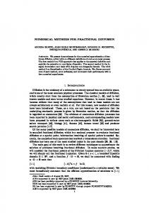
Figure 1.2: On the left the semi-lunar valves from a laid open aorta. On the right are the base of the ventricles after removal of the atria. Both images from Gray’s Anatomy of the human body [76].
2
Arterial stenosis is a narrowing or blockage of an artery and can be fatal if it hits a major artery such as the carotid. It can be caused by the deposition of dead cells forming an occlusion or simply due to Diabetes, high blood pressure, tobacco, ... which causes the artery to physically reduce its diameter. 3 A stent is either an expandable wire form or perforated tube (conventionally perforated by means of laser cutting) that is inserted into a natural conduit of the body to prevent or counteract a disease-induced localized flow constriction. 4 An artificial heart valve is a device which is implanted in the heart of patients who suffer from valvular diseases in their heart. When one or two of the four heart valves seen in Fig. 1.2.1 (mitral, tricuspid, pulmonic, aortic) of the heart have a malfunction, the choice is normally to replace the natural valve by an artificial valve.
4
CHAPTER 1. INTRODUCTION
1.2.2
Cardiovascular valves
The main topic of this thesis in the modelling and the simulation of the interaction of blood and valves. Structure and fluid modelling, as well as the numerical methods will be addressed in the next chapters. We present in this section a few medical problems related to the cardiac valves. The cardiovascular system is mainly composed of the cardiac pump and a circulatory network. The heart is made of two synchronized pumps in parallel, composed of two chambers. The left heart valve (see Fig. 1.3) pumps blood through the systemic circulation and the right heart valve pumps through the pulmonary circulation. The aortic valve is charged to let oxygenated blood flow from the heart left ventricle into the aorta (see Fig. 1.3) and blocking the passage in the other sense. The aortic valve is composed of three cusps or leaflets of half
Figure 1.3: Half-plane Anatomical sketch of the aortic valve and the heart (from Nucleous Communications Inc).
moon shaped connective tissue (see Fig. 1.2) that, in response to the pressure gradients imposed by the blood, passively move apart or mate together. Subvalvular Stenosis Stenosis can be defined as an abnormal narrowing of the blood vessels. It can however also be applied to a rigidification phenomena in the valve which creates an artificial narrowing of the blood vessel. This can be due to a series of conditions such as rheumatic fever5 , calcification6 (see Fig. 1.5 and Fig. 1.4) or even congenital malformation 5
Rheumatic fever is an inflammatory disease. It can affect many of the body’s connective tissues, especially those of the heart, joints, brain or skin. Anyone can get acute rheumatic fever, but it usually occurs in children five to 15 years old. The rheumatic heart disease that results can last for life. 6 Aortic valve calcification (sclerosis) is a condition in which calcium deposits form on the leaflets of the aortic valve in the heart.
1.2. VALVES IN THE CARDIOVASCULAR SYSTEM
5
Figure 1.4: Sketch of a stenotic aortic valve due to calcification, which can be seen on the inner sides of the visible leaflets (from wikipedia).
such as Bicuspid aortic valve7 . These factors prevent the valve from opening properly, and thus normally functioning. Once the condition develops, high overpressure builds up in the left ventricle and can seriously injure the heart. Aortic stenosis affects approximately 5 out of every 10,000 people in the Western countries (see e.g. [1]). There are several techniques available for the detection of such a condition such as Doppler echocardiography8 and catheterization9 that give quantitative measures which can be later evaluated to determine the seriousness of the situation. In Section 1.2.3 we will discuss, following the works of Garcia et al in [66], the correspondence of a certain index, the energy loss with respect to the actual phenomenon. Valvular regurgitation Valvular regurgitation, or valvular incompetence or insufficiency, is a condition, in which due to the malfunction of one or several valves provokes an improper closure thus allowing the blood to leak 7
In bicuspid aortic valve, there are only two leaflets instead of three and the valve leaflets are often thickened. It occurs when the aortic valve does not develop normally while the baby is in the womb. It is one of the most common congenital heart defect affecting about 20 per 1000 babies born. 8 Doppler echocardiography is a procedure which uses ultrasound technology and was originally developed to examine the heart. It creates an image of it and measures the speed and direction of blood flow. This procedure is frequently used to examine children’s hearts for heart disease because there is no age or size requirement. 9 A small puncture is made in a vessel in the groin, the inner bend of the elbow, or neck area (the femoral vessels or the carotid/jugular vessels), then a guide-wire is inserted into the incision and threaded through the vessel into the area of the heart that requires treatment, visualized by fluoroscopy or echocardiogram, and a catheter is then threaded over the guide-wire.
6
CHAPTER 1. INTRODUCTION
Figure 1.5: Four types of calcified aortic stenosis from [44]. In each, the unopened aortic valve is viewed form above. A. Acquired bicuspid aortic valve with secondary calcification. At the center of the conjoined cusp (lower center) are elements of two preexisting cusps, now fused. B. Congenital bicuspid valve. The characteristic raphe of the congenital bicuspid aortic valve appears at the lower portion of the figure. C. Senile type. None of the commissures is fused, but there is a major intrinsic calcification of the three cusps. D. Unicuspid, unicommissural congenital aortic stenosis with secondary calcification.
1.2. VALVES IN THE CARDIOVASCULAR SYSTEM
7
in the wrong direction (see Fig. 1.6). This condition can occur in any of the four heart valves, the aortic, the mitral, the tricuspid or the pulmonic. And can be at the origin a subvalvular stenosis. In a normal slash healthy heart
Figure 1.6: Valvular regurgitation is characterized by inappropriate retrograde flow during the cardiac cycle. The left panel demonstrates mitral regurgitation in systole, the right panel demonstrates inappropriate aortic insufficiency in diastole (from [3]). these previous valves allow blood to flow only in one direction and only at the right time during a heartbeat. Notice that due to intense pressures (see Fig. 1.7) the Mitral valve has attachment fibers called chordae tendineae, or heart strings, to prevent the flaps from everting into the left atrium (and the tricuspid from everting to the right atrium). On this subject, the method developed in Chapter 5 to deal with contact can be easily adapted to take into account these attachments in fluid-structure interaction simulations (see Remark 5.1). Mild Valvular regurgitation may not show any symptoms, but it could lead to more serious problems, such as heart failure, as the leak worsens. As acknowledged, the main effect of valvular regurgitation is the change in the flow direction. There is a second non neglectable effect, turbulence due to regurgitant jets originating from small irregular openings. These jets are made of many different velocity vectors and complex flow patterns. The third factor associated with the described condition is an abnormal pressure difference that may be, in time, heart damaging. For instance being able to couple the presence of valves in the heart with its electromechanical part as well as heart, aorta, coronaries, pulmonary blood flow and perfusion would bring about a quite complete model which could in its stead help to reach
8
CHAPTER 1. INTRODUCTION
Figure 1.7: During systole, left ventricular pressure is greater than left atrial pressure (left panel). In the presence of mitral regurgitation, the flow communication between these chambers allows a high gradient to exist (from [3]). a better understanding of the flow patterns and possibly pave the way to better patient specific valve shape design. Artificial valves Artificial heart valves are prosthetics constructed to emulate the function of normal heart valves. As a result of a number of diseases (two of which were described previously), they acquire defects which impedes them from functioning normally. These conditions burden the heart and since it may lead to heart failure, there is an interest in its replacement. There are presently two types of valves used in the replacement of the aortic valve, mechanical and tissue. None of which is now in place to be considered a definite replacement. While mechanical valves can last indefinitely (tests refer to approximately 50000 years), they require a lifelong treatment with blood thinners, or anti-coagulants. On the other hand, tissue heart valves (usually from pig cells) do not require the use of anticoagulant drugs, but have a rather limited lifespan of approximately 15 years. Between the use of blood thinners that leave people vulnerable to bruises and the fact that the survival rate drops dramatically with each new open heart surgery, present procedures leave space for improvement. In view of the simplicity of the mechanical valves, we chose to start the present work with a simple rigid mono-dimensional valve in a bi-dimensional domain. Nevertheless, for realistic valves as well as for tissue prosthetics valves, more complex structural models are needed and will be also presented
1.2. VALVES IN THE CARDIOVASCULAR SYSTEM
9
Figure 1.8: Example of two mechanical valves (top) and a tissue valve (bottom) used in heart valve surgery (from University of Birmingham and CVT Surgical Center, respectively).
in this thesis.
1.2.3
Clinical assessment of stenosis
In this section we try to explain how numerical simulations of valves can help to improve clinical decision in a very specific case presented before: the aortic subvalvular stenosis. In general, when dealing with the establishment of guidelines for the diagnosis and treatment of a certain pathology, the relevant steps are: (i) identify the physical causes of certain symptoms: in the case of the aortic stenosis, the narrowing of the valve leading to reduced blood flow and pressure buildup inside the heart that can produce chest pain, fainting, loss of consciousness, rapid or irregular heartbeats;
10
CHAPTER 1. INTRODUCTION
(ii) identify appropriate synthetic indexes evaluable with diagnostic tools (in case of suspect aortic stenosis, Doppler and catheterization are generally used) that provide a quantitative measure of the above physical phenomena and can drive the clinical diagnosis and the treatment of the patient; (iii) evaluate the validity of these indexes with respect to their adherence to the actual outcome of the pathology. It seems out of reach for the moment to purely use numerical simulations to move from (i) to (ii) and statistical studies seem to be the tool the most adapted to point (iii). Nevertheless, numerical simulations might play an important role in evaluating the foundation of a specific clinical index that is supposed to measure a relevant physical quantity (step (ii)). Indeed, in general very strong assumptions and several simplifications are done to derive practical indicators. Numerical simulations may thus help to assess the correspondence of a certain index with respect to the actual complex physical phenomenon. In the case of the aortic valve stenosis, it is generally accepted that a relevant synthetic index is the so-called Effective Orifice Area (eoa), which is the minimal cross-sectional area of the flow jet, attained downstream the valve. The eoa can be measured either by Doppler or by catheterization. It has been recently advocated in [66] that the energy loss through the valve could be a better indicator of the effect of the stenosis on the overall hemodynamic field. The authors propose an energy loss index that can be derived from non-invasive measurements. Validation of this index has been carried out in [66] by performing statistical studies that show how the energy loss index has a more significant correlation with the mortality and morbidity of several patients with respect to other indexes as for example the eoa. Concentrating on the energy loss, numerical simulations can be used in the sense advocated above, that is to assess whether this indicator reflects the “true” energy loss computed by the mathematical model. It must be however underlined that the mathematical modelling and the numerical simulation of fluid-structure interaction problems involving valves is a very hard task (large displacements of the structure, contact modelling, . . . ), and lots of progress has still to be done before being able to address the physical problem in all its complexity. This thesis can be viewed as a first step towards this goal. In appendix 8.1 we give more details on the effective computations of the various indexes briefly presented here. We also refer to [79] where the issue of the clinical assessment of prosthetic valve in presence of subaortic stenosis is addressed.
1.3. NUMERICAL METHODS FOR IMMERSED STRUCTURES
1.3
11
Numerical methods for immersed structures
In this section we will present a small resume of the methods and techniques that were available when the work presented on this thesis was being done. Hereafter we will present the separate methodologies that can possibly be applied to our problem. Thus we will begin with the immersed boundary methods and then go to the Fictitious domain methods. We will present the reasons that led us to the use of the Fictitious Domain/Lagrange multiplier approach to tackle the immersed valve movement. Various approaches have been investigated to model fluid-structure interaction problems involving valves (as in heart valves). The Arbitrary Lagrangian Eulerian (ALE) formulation consists in using moving meshes which follow the valve movements. It has been used for example by Jianhai et al. [86] to study the 2D behavior of an artificial valve (rigid body), and by Le Tallec and Mouro [90] to study valves in hydraulic shock absorbers used in cars. In presence of very large displacements, ALE algorithms need frequent remeshing, which may introduce diffusion in the numerical solution. Moreover, by construction, ALE is not adapted to topological changes which occur for example when the valves close. Other methods are based on a priori fixed meshes. This is the case of the immersed boundary method by Peskin (see for example [103] among many references on the subject). In this approach, fluid and structure are solved simultaneously: the interaction with the structure is taken into account using an external force acting on the fluid. Another possibility is to consider independent meshes for the fluid and the structure. The coupling is then obtained by enforcing the kinematic condition with Lagrange multipliers. This is the basic idea of the so-called Fictitious Domain (FD) method which has been much investigated by Glowinski and co-workers (see for example [74, 71, 73]). In fluid-structure interaction problems, the FD method was originally used for rigid particles. But it has also been applied for flexible structures, either using Lagrange multiplier located on the structure surface (see the works by Baaijens and co-workers [6, 34, 121]) or Lagrange multiplier located on the structure volume [124]. If FD has been originally designed for fixed meshes, it appears that it may also be interesting to use it on moving meshes, mixing ALE and FD formulations (see [33]). Indeed, if FD is a powerful method for valves, ALE formulation is more accurate and robust as far as the wall is concerned. In blood flow applications, it is useful to take into account both wall and valve movements: for example, it is shown in [117] that the compliance of the aortic root contributes to the leaflet opening and to the ability of the aortic valve to increase its effective orifice area when necessary.
12
CHAPTER 1. INTRODUCTION
1.3.1
Immersed Boundary methods
One of the first people to try to deal with biological flows in fluid-structure interaction realm was Peskin, in 1972, in order to simulate cardiac mechanics and blood flow (see [103]). The Immersed Boundary method as it was later called is still widely used nowadays in fluid dynamics. It consists in using Lagrangian and Eulerian coordinates linked together using interaction equations that involve smoothed approximations of the Dirac delta function. The major advance proposed by this method was the use of a fixed cartesian mesh for the fluid and an independent structure entity immersed in the fluid. The way by which the structure acts on the fluid is done by means of a force carried along the interface. On the boundary, Lagrangian markers are placed and these markers are tied together by a stiff spring to its position in space. Every deviation of these markers generates the force. The equations were the incompressible Navier-Stokes in their standard Eulerian formulation with the added Lagrangian terms to take into account the elastic force density coming from the immersed solid. Here are the equations derived by Peskin: ρ
�
ρ(x, t) = F (x, t) =
� ∂u + u · ∇u + ∇p = µ∆u + F ∂t ∇·u=0 Z Z
M (q, r, s)δ(x − X(q, r, s, t))dq dr ds
f (q, r, s, t)δ(x − X(q, r, s, t))dq dr ds
(1.1)
∂X (q, r, s, t) = u(X(q, r, s, t), t) ∂t ℘E f =− , ℘X
where E(X(q, r, s, t)) is the elastic energy stored in the material at time t, f represents its Fr´echet derivative and ℘ is the perturbation operator, M is the R mass density such that Q M (q, r, s)dq dr ds is the mass of the piece of the material defined by (q, r, s) ∈ Q, f is the elastic force density. The quantity E(X(q, r, s, t), in physical terms is minus the force density generated by the elasticity of the material. The proposed algorithm for this method is: - knowing all the information of the time step n, first find the positions of the Lagrangian markers at time n+1/2 bearing in mind the Eulerian local grid gh X n+1/2 (q, r, s) = X n (q, r, s) +
∆t X n u (x)δh (x − X n (q, r, s))h3 2 g h
1.3. NUMERICAL METHODS FOR IMMERSED STRUCTURES
13
- from the Lagrangian markers calculate the elastic force f n+1/2 (q, r, s)∆q∆r∆s = −
∂Eh (X n+1/2 ) ∂X
- propagate the Lagrangian force and mass densities on the Eulerian grid P F n+1/2 (x) = (q,r,s)∈Gh f n+1/2 (q, r, s)δh (x − X n+1/2 (q, r, s))∆q∆r∆s P ρn+1/2 (x) = (q,r,s)∈Gh M (q, r, s)δh (x − X n+1/2 (q, r, s))∆q∆r∆s - solve the Navier-Stokes equations on the Eulerian grid gh obtaining un+1/2 and p˜n+1/2 by the finite difference method
- update the Lagrangian configuration from X n to X n+1 interpolating the velocity un+1/2 to X n+1/2 X X n+1 (q, r, s) = X n (q, r, s)+∆t un+1/2 (x)δh (x−X n+1/2 (q, r, s))h3 x∈gh
- re-evaluate the Navier-Stokes equations using the same ρn+1/2 and f n+1/2 and determine un+1 and pn+1/2 In particular, at each time step there is just the fluid system to solve with an added force term which also reflects a significant reduction of the computational cost. This method, however, produces a problem difficult to circumvent, which is to find a consistent approximation of the Dirac delta measure carried over the immersed boundary. Xi+1
Xi
Xi−1
Figure 1.9: Example of a typical immersed boundary where springs are used to enforce the structure forces The Dirac delta intervenes in two different stages in the IB algorithm, in the expression of the structure forces acting on the fluid and in the displacement of the structure (from the found fluid velocity). The first stage
14
CHAPTER 1. INTRODUCTION
defines action-reaction effect, imposing the conservation of forces at the interface. The second translates as the kinematic condition which states that the structure must move itself at the same velocity as the fluid that surrounds it. -3
-2
-1
0
1
2
2 1.8
1.8
1.6
1.6
1.4
1.4
1.2
1.2
1
1
0.8
0.8
0.6
0.6
0.4
0.4
0.2
0.2
0
0 -0.2 -2
-1
¯ ¯˙¯ ¯¯ ˙˙˙
0
1
2
3
IB traditional δh function Cubic spline generator for RKPM second order RKPM function fourth order RKPM function
Figure 1.10: Discretized delta functions according to different techniques. � 1 πr From the traditional 4 1 + cos( 2 ) function to the more recent reproducing kernel particle method. In this methodology, Peskin proposes the construction of a discrete Dirac delta, δh (Fig. 1.10) that must: be continuous to prevent the jump of the velocity across the immersed structure or on the applied forces; have a compact support to save computational time; be exact for linear interpolation, to make sure the moment of the forces across the interface is conserved; have the smallest possible support. Since its inception, this technique has been applied to a variety of problems such as, prosthetic cardiac valves, platelet aggregation during blood clotting, swimming motion of eels, sperm and bacteria, dynamics of wood pulp fibers, and others. From the “Immersed Boundary method” many other methods were born, such as the extended immersed boundary method, the immersed finite element method and the Fictitious domain method, just to name a few. The extended immersed boundary method (EIBM) developed by Wang X. and Liu W.K. (see [123]) and the Immersed finite element method (IFEM) developed by Zhang et al (see [126]) were developed as modifications on the IB, where instead of immersing a volume-less structure in the fluid mesh, it was chosen to submerge an elastic solid occupying a finite volume. Fur-
1.3. NUMERICAL METHODS FOR IMMERSED STRUCTURES
15
thermore the discretization of the Dirac delta measure was done with kernel functions (see [92]), using the meshless RKPM (Reproducing kernel particle method). This allowed the Dirac delta function continuity to pass from C 1 to C n and thus enabling this method to be more computational efficient for large displacements. The kinematic matching of the fluid-structure interface was also changed applying an equivalent ensemble of nodal forces presented in variational form. Using a cluster of Lagrangian points the force density is computed, by discretizing the stress-strain equations of the elastic solid on a grid (first developed in [118]). This allowed a deeper connection between the traditional elasticity model and the IB method. The connection was enhanced even further by employing the internal nodal forces in the context of the finite element method. Another modification to the IB was brought about by Boffi and Gastaldi and was based on a finite element approximation (see [14, 15, 16]). In this approach, the load term which comes from the fact that there is a boundary/structure in the fluid is treated in a variational form. So the following F (x, t) =
Z
L
0
f (s, t)δ(x − X(s, t)) ds,
in Ω×]0, T [
will be represented, when the structure is a closed line, as hF (x, t), vi =
Z
L
f (s, t)v(X(s, t)) ds
Z0 L
∂ 2 X(s, t) v(X(s, t)) ds, κ ∂s2 0 Z L ∂X(s, t) ∂v(X(s, t)) = −κ ds, ∂s ∂s 0
=
∀v ∈ H01 (Ω)
where κ represents the elasticity coefficient. They take into account an F such that the movement of the boundary, here depicted as X, is driven by its elastic energy. All these modifications allowed the method to pass from a finite difference scheme to a finite element scheme.
1.3.2
Fictitious domain methods
An alternative way to solve problems of solids immersed in fluids is to use the fictitious domain (FD) method. The general idea is to find the solution to a given problem by extending the given data to a larger and simpler shaped domain, which contains the original domain. As far as can be traced, Saul’ev [115], in the 1960’s, was the first author to refer to the term fictitious domain applied to such an approach, then followed by Rukhovets [112] in 1967 and by Kopˇcenov [89] in 1974. The method has also been known as domain imbedding (embedding) method [18, 19] or fictitious component method
16
CHAPTER 1. INTRODUCTION
[5]. The fictitious domain was typically a rectangle or a circle and was discretized on uniform meshes independent of obstacle boundaries, which avoided the construction of boundary fitted meshes. Nowadays several different approaches to the FD have been studied. These will be described in the following subsections. Fat boundary method This approach known as FBM was first developed by B. Maury [95] to solve a Poisson problem in a domain with holes. The basic idea was to replace the initial problem with an equivalent one defined in a simpler domain. This simpler domain is such that a cartesian mesh is allowed which in its stead permits the use of fast solvers and efficient pre-conditioners. The original problem now poses itself as two sub-problems, one global and one local. The global problem is defined on a domain that encapsulates the perforated domain. The local problem is defined in a neighborhood of the holes and a finer mesh can be considered in order to better approximate the solution. Later, in M. Ismail PhD thesis [84], this method was applied to the case
Ω
γ
γ′ Figure 1.11: 2D example of the global and local meshes for the FBM where the domains’ holes are allowed to move (for example the presence of air pockets inside a fluid). It employs an approximated interface whose support is larger than the physical domain. For example by using source terms such as the discrete Dirac delta measure over a larger interface (see section 1.3.1 where Peskin’s approach was described or Rukhovets [112]). Here a cartesian mesh is used and a second “fat”mesh is constructed around each hole’s border. The resolution is mainly divided into two phases, an interpolation of the global velocity field onto the artificial interface γ ′ (based in the domain decomposition approach with full overlapping proposed in Le Tallec-Tidridi
1.3. NUMERICAL METHODS FOR IMMERSED STRUCTURES
17
[91]) followed by a regulation of the jump of the normal derivative of the velocity across γ (as it is done in the IB method prescribing an appropriate discrete Dirac delta measure). This methodology allows the global problem over the cartesian mesh to be solved using fast solvers such as the FFT (Fast Fourier Transform) while the solution for the local problem can be accurately approximated in a neighborhood of the actual hole. Lagrange multiplier This Lagrange multiplier approach, employs an approximation of the interface without any enlargement on the exterior normal direction. In this approach Glowinski et al were the pioneers developing the method called FD/LM (Fictitious Domain/Lagrange multiplier) which his team then applied to particle flows and to rigid volumic bodies immersed in fluids. Some of the related bibliography can be found in [70, 71, 73, 74, 87, 102] and in the references therein. The FD/LM consists in imposing the boundary condition in the variational formulation with the help of Lagrange multipliers and bringing about a saddle point formulation. Glowinski’s group stated two different kinds of approach to the Lagrange multiplier method. One, a surface approach and another, a distributed approach. • Boundary Lagrange multiplier In this approach the Lagrange multipliers are only present in the surface of the immersed surface and thus are defined in a space therein. This means that there is only the need to mesh the surface (see Fig. 1.12). Examples of this type of approach can be found in [70].
Figure 1.12: Example of the surface Lagrange multiplier approach where the Lagrange multiplier are only applied on the boundary of the immersed surface, letting the fluid flowing within. This is basically the approach we have followed in our work [23, 43].
18
CHAPTER 1. INTRODUCTION • Distributed Lagrange multiplier Another approach based on the Lagrange multiplier is to consider the multipliers distributed on the whole immersed domain (see Fig. 1.13). This means that the space in which they are defined is no longer just
Figure 1.13: Example of the distributed Lagrange multiplier approach where the Lagrange multiplier are applied on the whole immersed surface. the bounding surface, but the whole volume delimited by it, thus the interior of the structure needs to be meshed. Examples of this type of approach can be found in [71] and in [102]. For the case we will be studying it is in fact irrelevant whether we use one or the other. The immersed structure we aim at simulating is a surface in 3D or an open line in 2D and this means there is only the border to discretize (which also defines the whole solid).
1.3.3
Penalty method
This approach takes into account the classical Dirichlet, Neumann or Fourier boundary conditions on the immersed structure averaging them with a penalization method. In the weak formulation of the Navier-Stokes equations it consists in adding a term such as Z 1 u · v. ε Im This method was recently applied by DelPino and Pironneau to create FreeFem3D, a general 3d PDE solver (see [36, 38]), as a way to conciliate the implementation of boundary conditions over complex boundaries with simple mesh generation. Bruneau, Angot and coworkers (see [4, 88]) developed similar methodologies for the resolution of the Navier-Stokes equations around (possibly porous) solids. Janela, Lefebvre and Maury in [85] developed a simple method to simulate the movement of a thick valve by
1.3. NUMERICAL METHODS FOR IMMERSED STRUCTURES
19
penalizing a rigidity constraint in the fluid.
1.3.4
Algebraic FD
Fictitious domain methods have also been used to construct a preconditioner for iterative methods such as Krylov subspace methods. One such approach is called an algebraic fictitious domain method (see e.g. [19, 94]). In the algebraic variant of the FD, the discretized linear system matrix is enlarged (thus the name algebraic) and will act as a preconditioner on the resolution. Typically these methods are solved in locally fitted meshes as in Fig. 1.14
Figure 1.14: Example of a locally fitted mesh. where the mesh is modified on a local level to take into account the shape of the immersed structure. This method was recently used by Del Pino, Heikkola, Pironneau and Toivanen in [37] to solve the three dimensional Helmholtz equation. For more references to this method we refer to, for example, [13], [81] and [80]. The main advantage of this approach is that there are more possibilities to build efficient preconditioners for the enlarged system than for the original one.
1.3.5
ALE and adapted meshes
The ALE (Arbitrary Lagrangian Eulerian) represents a strong and reliable approach, but also an expensive one, since the mesh follows the movement of the solid, adapting its shape to the whims of the structure. By reliable approach we refer to the fact that the loads on the structure as well as jumps of pressure can be, a priori, more accurately recovered. In particular even if the pressure finite element functions are continuous, it is easy to “duplicate” the points on the thin structure in order to capture a pressure discontinuity in the fluid10 . The ALE method is one of the most widely used methods to solve fluid 10
Duplicating the points means that over each structure point two independent nodes are considered.
20
CHAPTER 1. INTRODUCTION
Figure 1.15: Example of a globally adapted mesh using the ALE for a valve of 0.45cm on a 1cm high tube. structure interaction problems (see section 3.2 for a brief explanation of this method). This method has however two major drawbacks. For one, if the movements are too large, the elements will become deformed. The other is that this method cannot handle changes in the topology, such as contact. Even if the first drawback can be tackled with using remeshing algorithms, the second cannot be dealt with in a straightforward manner. In the sequel of this work we will use two methods: the fictitious domain (FD) method with Lagrange Multipliers and the ALE method. The purpose is twofold: • First, ALE will be used for the purpose of benchmarking. We will see in particular in section 4.5.3 that FD and ALE are in good agreement as soon as the fluid mesh is sufficiently refined. • Second, we will couple ALE and FD. The former being the more accurate to deal with wall movement, the latter being well-suited to deal with very large displacements and contacts.
1.4
Structure contact issues
The function of valves is to close and to prevent backflow. The question of contact between valves is therefore non avoidable.
1.5. THESIS OVERVIEW
21
We can cite a few works where this question has been treated. For example the work of Mouro during his PhD thesis [98] on hydraulic shock absorbers. More recently there have been some groups working on the contact between solids immersed in a fluid. For instance Glowinski et al. treated the case of contact between rigid particles immersed in fluid in [71, 72]. Van Loon et al. treated simple contacts between an immersed structure and a rigid wall, in a monolithic fashion (see [122]). The question of contacts in fluid-structure interaction problem is extremely complex, in particular because of the presence of lubrication forces. We will not consider this specific point in this work. Another difficulty is the treatment of multi-body contact, which occurs for example when the three leaflets of the aortic valves close. We will address this problem in Chapter 5 where we present a new algorithm well-suited to the partitioned fluid-structure schemes.
1.5
Thesis overview
This thesis organized in 6 chapters. Our main contributions are presented in Chapters 4, 5 and 6. In Chapter 2, we present the models for the fluid and for the structures. Three models will be used for the structure: for the 2D simulations we will consider rigid and elastic 1D structures; for the 3D simulations a nonlinear thin shell model will be used. In Chapter 3, we draw an overview of the algorithms and the known issues of fluid-structure interaction (FSI) problem in haemodynamics. In particular we present the Arbitrary Lagrangian Eulerian (ALE) formulation and we discuss the problem of weak and strong coupling and we present an semi-implicit algorithm developed for the fluid-wall interaction. This method will be extended in Chapter 6 to treat the cases involving immersed structure. In Chapter 4, we present fluid-structure interaction problems based on Lagrange multipliers in order to simulate immersed thin structures. According to the usage in the literature, we call this method the Fictitious Domain (FD) method. Various numerical simulations are presented, both in 2D and 3D, to assess the precision and the robustness of the proposed approach. In Chapter 5, we present our strategy to manage contact in a fluidstructure framework. We first study the valve-rigid wall contact. We next extend the algorithm to the case of multi-body problems which are important for the practical applications (the aortic valve being made of 3 leaflets). Numerical simulations are presented in 2D. In Chapter 6, we propose to couple the ALE and the FD formulations in order to treat with the most convenient methods both the wall and the
22
CHAPTER 1. INTRODUCTION
valves movements. We present a semi-implicit algorithm to efficiently treat this kind of coupling. Preliminary numerical results are presented. We also present 3D simulations in a realistic aorta geometry.
Chapter 2
Fluid and structure modelling In this chapter, we present the models that will be used in the sequel for the fluid and the structure. In each case, we briefly describe the physical assumptions and we give a few indications on the discretization methods.
2.1
Fluid model
Modelling Blood is not strictly speaking a fluid but rather a suspension of particles. The red blood cells, which constitute almost half of the volume of the total blood, are the main responsible for a complex mechanical behavior. For example, the blood viscosity increases when the deformation rate decreases (shear-thinning effect) because the red blood cells tend to aggregate. In the small vessels, the blood viscosity decreases when the vessel radius decreases because red blood cells move to the central part of the vessel (FahraeusLindquist effect). The elasticity of the red blood cells is also responsible for viscoelastic effects in the blood. Shortly speaking, one can say that these effects are important in small vessels or at low deformation rates. In this work, we only consider large vessels. The fluid will be therefore assumed to be Newtonian. It is generally admitted that turbulence is not present in the cardiovascular system in physiological situations. Nevertheless, it is likely that the flow is transitional at the exit of aortic valves. In this work, for simplicity, we will suppose that the flows are laminar. In conclusion, the fluid will be governed by the classical incompressible 23
24
CHAPTER 2. FLUID AND STRUCTURE MODELLING
Navier-Stokes equations:
ρ
�
� ∂u + u · ∇u − div (σ) = 0 ∂t div u = 0
for x ∈ ΩF (t),
(2.1)
for x ∈ ΩF (t).
where u is the fluid velocity, p the pressure and ρ the fluid density. The Cauchy stress tensor is denoted by σ = −p I + 2η D(u), where I is the identity tensor, D(u) is the strain rate (∇u + ∇uT )/2 and η the dynamic viscosity. The fluid domain ΩF is a priori time dependent because of the movement of the vessel walls and the valves. Discretization Problem (2.1) is discretized in time by a semi-implicit Euler scheme:
un+1 − un + ρun · ∇un+1 + ∇pn+1 − div (2ηD(un+1 )) = 0, δt div un+1 = 0. (2.2) The space discretization is done with finite elements. Most of the numerical computations done in this work are based on stabilized finite element with a P1 velocity and P1 pressure or a Q1 velocity and Q1 pressure (see e.g. [64, 107]). Nevertheless, for benchmarking, we have occasionally used stable pairs like Q2 /Q1 , Q2 /P1 . The pair Q1 /P0 (in general unstable) has also been used in a few cases. Except for the Q2 /P1 or Q1 /P0 , all the finite element spaces we used have a continuous pressure. A pressure jump being expected through the valve, the use of a discontinuous pressure space may be preferable, as mentioned in [6]. Nevertheless, the valve mesh being independent from the fluid mesh, the pressure jump can a priori occur within an element and this discontinuity cannot be catched, even with a discontinuous pressure finite element (whose discontinuity occurs only at the fluid element boundary). An enrichment of the pressure functions (in the spirit of the so-called Xfem method) depending on the valve position would be probably more accurate. We do not investigate this issue here. With a sufficiently fine grid, the results we obtained computing the stress jump in a variational way, as explained in Section 4.3, were satisfactory. But we believe that there is room for improvement in the pressure discretization. More specific issues, like the management of the moving domain and the fluid-structure coupling will be addressed in the next two chapters. ρ
2.2. STRUCTURE MODELS
2.2
25
Structure models
The mechanical characterisation of the artery wall or of the aortic valves is beyond the scope of the present work. We refer the reader to [33] and [83] for insights into these topics. In the sequel, we present three structure models which have been used in our simulations.
2.2.1
Rigid structure
Modelling Due to the complexity of the problem we decided to begin this study with a simpler one: the valve was supposed to be monodimensional, rigid and immersed in a 2D fluid. Note that the interest of using rigid structures for cardiac valve is not just academical: they can indeed model the artificial mechanical valves commonly used to replace the aortic valves. So even if the model is simple and easy to implement its scope is larger than one could originally consider.
Central axis
ey ex C
ez Ventricle
Valve
Aorta
Figure 2.1: Bi-dimensional scheme around the area of interest. The valve has only one degree of freedom, which is its rotation angle θ about a fixed axis (see Fig. 2.1). The equation governing the angle is a single ordinary differential equation, which expresses the conservation of the angular momentum d2 θ (2.3) J 2 = MΣ , dt J being the leaflet’s inertia momentum and MΣ the external momentum applied to the leaflet. Note that this external stress comes uniquely from the hydrodynamics stress.
26
CHAPTER 2. FLUID AND STRUCTURE MODELLING
We denote by Σ(t) the domain occupied by the structure and by X the reference coordinates of its points. The current positions of the valved points x(t) ∈ Σ(t) at time t ∈ (0, T ) are given by: � � cos θ − sin θ Cx(t) = Mθ CX with Mθ = . sin θ cos θ where Mθ is the rotation matrix of angle θ. Thus the structure’s domain is given by: � Σ(t) = x(t) = C + Mθ(t) CX .
Also the issues related to fluid-structure coupling will be addressed in details in the next two chapters, we give here some useful remarks on this topic. The fluid-structure coupling takes place on the fluid-structure interface. Since the structure is immersed and has one dimension less than the fluid, we will assume that the interface actually coincides with the structure’s domain Σ(t) (neglecting the thickness of the structure). The continuity of the velocities – the so-called kinematic conditions – on the interface reads: u(x(t), t) = ω ez × Cx(t),
(2.4)
for x(t) ∈ Σ(t), t ∈ (0, T ) and with ez as indicated on Fig. 4.4 and where we have defined the angular velocity ω=
dθ . dt
The momentum on the structure is given by: Z Cx × F Σ dl(x) MΣ (t) = Σ(t)
t ∈ (0, T ),
where F Σ is hydrodynamics force that will be precisely defined in next chapters (see equation (4.13)). Discretization The rigid structure is so simple that it could have been implemented directly in the fluid solver. Nevertheless, we developed a separated solver. By doing so, we were unrestricted to, later on, implement more complex structures without changing neither the fluid solver nor the coupling algorithm. The time discretization is performed with a mid-point scheme: ω n+1 − ω n = Mn+1 J Σ , δt (2.5) n+1 + ω n θ n+1 − θ n ω = , 2 δt
2.2. STRUCTURE MODELS
2.2.2
27
Elastic 1D structure
On the previous section, we treated a particular case were the immersed structure was rigid. We now present a model of a flexible valve. Modelling The structure is assumed to be mono-dimensional and inextensible. Its deformation energy is defined by 1 W (x) = 2
Z
L
0
2 2 ∂ x EI 2 ds, ∂s
(2.6)
where E denotes Young’s modulus, I the inertia, s is the curvilinear coordinate that goes from the structure’s fixation point to its apex, x(s) is the position vector of a point on the structure’s axis. The quantity EI represents the flexural stiffness. The solution is searched in 2 ∂x 2 2 ∂x ∈ (L (0, L)) ; = 1; K= x∈ ∂s ∂s (2.7) o ∂x (0) = 0 x(0) = 0 and ∂s which is the set of the allowed structure configurations that satisfy the boundary conditions as well as the inextensibility constraint. Thus, the configurations of the immersed structure are governed by the following problem: Find x(s, t) ∈ K such that for all t Z Z L Z L L (2.8) ∂2x ∂2ξ ∂2x EI 2 · 2 ds = F · ξds, ∀ξ ∈ K, m 2 · ξds + ∂t ∂s ∂s 0 0 0 n
(C 1 (0, L))2 ;
where m denotes the linear mass of the structure and F the external forces. In the sequel, F will typically be the hydrodynamic force F Σ (precisely defined in (4.13)). Nevertheless, in Chapter 5, F will also take into account contact forces F c . As in the rigid case, the fluid-structure interface is assumed to coincides with the structure domain Σ(t). The fluid-structure coupling is enforced through the following relations:
by
∂x (s, t) = u(x(s, t), t), ∂t
(2.9)
F (s, t) = F Σ (x(s, t), t),
(2.10)
It will be convenient to denote the structure velocity in x = x(s, t) ∈ Σ(t) def
uΣ (x, t) =
∂x (s, t). ∂t
28
CHAPTER 2. FLUID AND STRUCTURE MODELLING
Discretization and solution strategy The structure is discretized in time with the second order Houbolt scheme [93]. The solution xn+1 of (2.8) is found by solving the following problem: Find xn+1 ∈ K such that Z L Z ∂ 2 xn+1 ∂ 2 ξ L 2xn+1 − 5xn + 4xn−1 − xn−2 EI · ξds + · 2 ds = m 2 2 δt ∂s ∂s 0 0 Z L F n+1 · ξds 0
(2.11) for all ξ ∈ K. The first two steps are initialized with a Crank-Nicolson scheme since at that time iteration there is still not enough data to directly use the Houbolt scheme. The numerical solution of (2.11) is equivalent to finding the local minimum, on K, of the following functional 1 J(x) = 2 δt
2 2 Z L Z ∂ x 1 L F n+1 · xds m |x| ds + EI 2 ds − 2 ∂s 0 0 0 Z L 1 n n−1 n−2 + 2 m(−5x + 4x −x ) · xds. δt 0 Z
L
2
(2.12)
To account for the inextensibility constraint |∂s x| = 1, an augmented Lagrangian method is used. Following [20], we introduce the additional variable ∂x q= , q ∈ (L2 (0, L))2 , |q|2 = 1. ∂s We are then brought to the resolution of an equivalent problem, the search of a saddle-point {xn+1 , q n+1 , λn+1 } of the augmented Lagrangian L (x, q, λ) = J(x) +
Z
L
λ 0
�
∂x −q ∂s
�
r ds + 2
Z
The resolution is done with an Uzawa algorithm:
0
2 ∂x ∂s − q ds.
L
n+1 Let = λn and xn+1 = xn , compute 1 0 λn+1 n+1 qp which minimizes L (xn+1 ), with |q| = 1, p−1 , q, λp xn+1 which minimizes L (x, q n+1 , λn+1 ), p p ! p n+1 ∂x p n+1 n+1 , − q n+1 λp+1 = λp + r p ∂s
(2.13)
(2.14)
where r is a fixed parameter (see section 8.2.3 for details). This algorithm converges when p → ∞ to the saddle-point (xn+1 , q n+1 , λn+1 ), which means that (xn+1 , q n+1 ) minimizes L (x, q, λn+1 ) and λn+1 maximizes L (xn+1 , q n+1 , λ).
2.2. STRUCTURE MODELS
29
In order to find the solution for problem (2.14)1 , we solve ∂L n+1 (x , q, λn+1 ) = 0, p ∂q p−1 noticing that, J(x) being independent of q, this solution is obtained by minimizing at each point s, −(r
∂xn+1 p−1 ∂s
+ λn+1 )·q p
over the circle |q| = 1. This gives q
n+1
=
∂xn+1 p−1 ∂s ∂xn+1 p−1 |r ∂s
r
+ λn+1 p +
.
λn+1 | p
Problem (2.14)2 solution is obtained solving Z
Z L Z L ∂ 2 xn+1 ∂xn+1 ∂2ξ ∂ξ 2 p p · ds + r · ds + m xn+1 · ξ ds = p 2 2 2 ∂s ∂s ∂s ∂s δt 0 0 0 Z L Z L 1 n+1 m(5xn − 4xn−1 + xn−2 ) · ξds F · ξ ds + 2 δt 0 0 Z L ∂ξ (rq n+1 − λn+1 )· + ds ∀ξ ∈ K. p p ∂s 0 (2.15) The discretization of (2.15) is done using a third order Hermite finite element method in order to obtain an internal approximation of H 2 (0, L). We mesh the segment [0, L] with NΣ − 1 elements [si , si+1 ], such that s1 = 0 and sNΣ = L. We denote by hi the length of the interval [si , si+1 ]. The set of allowed displacements L
EI
Kh = {xh ∈ (Zh )2 :
∂xh ∂xh = q h , |q h |2 = 1 , xh (0) = 0, (0) = 0}, ∂s ∂s
where the finite element space is given by: Zh = {vh ∈ C 1 ([0, L]) : vh |[si ,si+1 ] ∈ P3 , 1 ≤ i ≤ NΣ − 1}.
2.2.3
Thin elastic shells
The two previous structure models were mainly used to test the various algorithms – fluid-structure coupling and contact – developed during this thesis. Nevertheless, realistic cardiac valves definitely need 3D simulations. To this purpose, we use a nonlinear thin shell model. Of course, this model is much more involved than those seen above. We therefore present it with more details than in the two previous sections.
30
CHAPTER 2. FLUID AND STRUCTURE MODELLING
Following I. Paris [101] and D. Chapelle & Bathe [27] we define a shell as a solid medium geometrically defined by a mid-surface S immersed in the physical space E . A parameter t is introduced, representing the thickness of the medium around this surface. The mid-surface is normally described by a collection of charts from domains in R2 into E (see Fig. 2.2). Note that even in complex configurations the analysis can be decomposed according to a certain chart and respective reference domain. Thus we will focus on shells represented using a single chart. From now on we will consider a shell with a ~ i.e. an injective mapping mid-surface S defined by a 2D chart denoted by φ, ~ ω )). from the closure of a bounded open subset ω ∈ R2 into E (S = φ(¯
~a3 ~a2
~ φ
ξ2
t
~a1
S ~x3
ω
~x1
~x2
ξ1 Figure 2.2: Geometric description of a shell
Modelling In general, mathematical shell models assume that any material line orthogonal to the mid-surface in the undeformed configuration remains straight and unstretched during deformation. This hypothesis is also known as the Reissner-Mindlin kinematical assumption. The displacements obtained when this assumption is considered can be expressed by ~ (ξ 1 , ξ 2 , ξ 3 ) = ~u(ξ 1 , ξ 2 ) + ξ 3 θλ (ξ 1 , ξ 2 )~aλ (ξ 1 , ξ 2 ). U In this equation it is considered a material line in the direction of ~a3 at the coordinates (ξ 1 , ξ 2 ). The displacement of ~u(ξ 1 , ξ 2 ) represents a global
2.2. STRUCTURE MODELS
31
infinitesimal displacement of the line with all particles on the line displacing by the same amount. The displacement of ξ 3 θλ (ξ 1 , ξ 2 )~aλ (ξ 1 , ξ 2 ) is due to the rotation of the line measured by θ1 and θ2 (see Fig. 2.3). The rotation of
~a3
~u
ξ 2 -curve S
θ1 ~a2
θ2
~a1 ξ 3 -curve
ξ 1 -curve
Figure 2.3: Kinematic assumptions for the material line orthogonal to the mid-surface S (Infinitesimal rotations assumed). an infinitely thin straight material line is solely defined by a rotation vector normal to that line (component ~a3 is disregarded). ~ (ξ 1 , ξ 2 , ξ 3 ), the covariant-covariant Thus given a general displacement U components of the linearized 3D Green-Lagrange strain tensor are defined as ~) = eij (U
1 ~ ,j + ~gj · U ~ ,i ), (~gi · U 2
i, j = 1, 2, 3
This linearized strain tensor (constructed taking into consideration the Reissner-Mindlin kinematical assumption) can be expressed as a function of the mid-surface displacement ~u and the surface rotation field θ = θλ~aλ . Using a covariant differentiation for surface tensors, we can evaluate (2.2.3) to obtain
eαβ
= γαβ (~u) + ξ 3 χαβ (~u, θ) − (ξ 3 )2 κα,β (θ)
eα3 = ζα (~u, θ) e33 = 0
(2.16)
32
CHAPTER 2. FLUID AND STRUCTURE MODELLING
with γαβ (~u) =
1 2 (uα|β
+ uβ|α ) − bαβ u3
χαβ (~u, θ) =
1 2 (θα|β
+ θβ|α − bλβ uλ|α − bλα uλ|β ) + cαβ u3
καβ (θ) = ζα (~u, θ) =
1 λ 2 (bβ θλ|α 1 2 (θα
+ bλα θλ|β )
(2.17)
+ u3,α + bλα uλ ).
The tensors γ, χ and ζ are called respectively membrane, bending and shear strain tensors. Considering an isotropic linear elastic material, Hooke’s law, in a general curvilinear coordinate system, defines the contravariant-contravariant stress tensor component as σ ij = H ijkl ekl with H ijkl = L1 gij gkl + L2 (gik gjl + gil gjk ) where L1 and L2 represent the Lam´e constants L1 = E
ν , (1 + ν)(1 − 2ν)
L2 =
E 2(1 + ν)
and E the Young’s modulus and ν the Poisson’s ratio for the material in consideration. The model is based on the assumption that the state of the stresses in the shell corresponds to plane stresses approximately tangent to shell’s mid-surface, that is, σ 33 = 0. Considering the presence of zero normal stresses an equivalent system of constitutive equations can be found, σ αβ = C αβλµ eλµ σ α3 = 21 D αλ eλ3 , with
C αβλµ = Dαλ =
E αλ βµ 2(1+ν) (g g
+ gαµ gβλ +
2ν αβ λµ 1−ν g g )
2E αλ 1+ν g .
Then the variational formulation reads Z Z � � αβλµ αλ ~ dV ~ ~ ~ ~ F~ · V C eαβ (U )eλµ (V ) + D eα3 (U )eλ3 (V ) dV = Ω
Ω
(2.18)
2.2. STRUCTURE MODELS
33
~ is the displacement unknown that satisfies the Reissner-Mindlin where U ~ is an arbitrary kinematical assumption as well as the boundary conditions. V test function ~ (ξ 1 , ξ 2 , ξ 3 ) = ~v (ξ 1 , ξ 2 ) + ξ 3 νλ (ξ 1 , ξ 2 )~aλ (ξ 1 , ξ 2 ) V
(2.19)
that satisfies the same assumption and considers zero displacement boundary condition. The quantity F~ is the exterior applied load. A basic shell model satisfies 2.18. There are other models that are constructed from this one, such as the s-m-b (shear membrane bending) and the m-b (membrane bending), considering additional assumptions. These will not be used in the present framework and thus we will refrain from developing the theory for such models. Discretization: MITC shell elements The MITC terminology stands for “Mixed Interpolation of Tensorial Components” and are general shell elements that are obtained using a 3D variational formulation. They are formulated in order to avoid numerical locking by using a specific interpolation strategy for each component of the strain tensor within each element, instead of deriving them directly from the displacements. The interpolation points for strains at the each element are called tying points (see e.g. [7]). The difficulties associated to the usage of shell elements are mostly due to numerical locking in bending-dominated shell problems and loss of consistency in membrane-dominated problems. To tackle both these difficulties the MITC approach was developed for quadrilateral shell (and also plate) finite elements (e.g. [8]). General shell elements constitute a category of finite elements widely used in engineering practice. They are mostly based on a degenerated three dimensional general formulation from continuum mechanics. This form gives a modified variational problem where we have: a plane stress assumption; a special mesh; displacement functions that satisfy the Reissner-Mindlin kinematical assumption on the nodes. The domain is meshed by nodes located in the mid-surface S and the curvilinear variables (ξ 2 , ξ 2 , ξ 3 ) are related to the local coordinates ˆ = Tˆ × [−1, 1] (r, s, z) ∈ K using the following relation inside each element: � � � 1 � k 1 X ξ ξ λi (r, s) (i) = 2 2 ξ ξ(i) i=1 ξ 3 = z 2t
(2.20)
1 , ξ 2 ) are the nodal coordinates in ω, {λ }k where (ξ(i) i i=1 is the 2D shape (i) functions set of a standard k-node iso-procedure. The domain Tˆ is to be
34
CHAPTER 2. FLUID AND STRUCTURE MODELLING s
1
s A
r −1
B
1
D
r
C −1
ehrz = a1 + b1s tying points A and C ehsz = a2 + b2r tying points B and D
θ and ~u interpolation
Figure 2.4: MITC4 shell element with its 4 interpolation points (left) and its 4 tying points (right). specified according to the type of element. For instance, in our case, for quadrangular elements Tˆ = [−1, 1]2 and thus (r, s, z) ∈ [−1, 1]3 (see Fig. 2.4). A general shell element has a position vector defined as ! k X t(i) (i) (i) (2.21) λi (r, s) ~x + z ~a3 ~x(r, s, z) = 2 i=1
(i)
where ~x(i) , t(i) and ~a3 denote the position vector in the global cartesian coordinate system, thickness and unit normal vector respectively, at a node i. The previous standard iso-parametric approach 2.21 is in relation with the the following approximate chart 1 2 ~ 1 , ξ 2 ) + ξ 3 I(t ~a3 )(ξ , ξ ) ~ h (ξ 2 , ξ 2 , ξ 3 ) = I(φ)(ξ Φ t
(2.22)
where I is the interpolation operator defined for a smooth function ψ as 1
2
I(ψ)(ξ , ξ ) =
k X
1 2 λi (r, s)ψ(ξ(i) , ξ(i) )
i=1
The subspace of discretized displacements is denoted by Vh and it mainly ~ obtained by varying the nodal positions and consists of displacements V normal vectors, ~ (r, s, z) = V
k X i=1
λi (r, s)~v
(i)
+z
k X i=1
λi (r, s)
� t(i) � (i) ~ (i) (i) ~ (i) α1 V1 + α2 V 2 2
2.2. STRUCTURE MODELS
35
~ (i) and V ~ (i) are orthonormal vectors where ~v (i) is the nodal displacement; V 1 2 ~ (i)
(i) ~ (i),V2 ,~a(i) } is an orthonormal base in respect to ~a3 and to one another ({V 1 3 (i) (i) (i) ~ (i) and for each i); α1 and α2 are the rotations of a3 with respect to V 1 ~ (i) respectively. However, V ~ (i) and V ~ (i) are often defined as follows: V 2 1 2
~1 = ~a3 ∧ ~e , V k~a3 ∧ ~ek
~2 = ~a3 ∧ V ~1 V
~e is a Cartesian base vector.
Remark 2.1. The Reissner-Mindlin kinematical assumption is satisfied at all mesh nodes since (i) η (i) · ~a3 = 0 ∀i ~ if (i) ~ (i) (i) ~ (i) η~(i) = α1 V 1 + α2 V2
is the rotation at node i. If an isotropic elastic material is considered, substituting the exact chart ~ Φ by (2.22) in the left hand side of equation (2.18), the discretized version of the internal work is given by: Z h i ~ h )¯ ~)+D ¯ αλ e¯α3 (U ~ h )¯ ~ ) √g¯dξ 1 dξ 2 dξ 3 ~ ~ C¯ αβλµ e¯αβ (U eλµ (V eλ3 (V A(Uh , V ) = Ω
(2.23) where the bar-symbol refers to the fact that the quantity is affected by the geometric approximation, i.e. ! ~ ~ ∂ V ∂ V 1 ~)= (2.24) · ~g¯j + j · ~g¯i e¯ij (V 2 ∂ξ i ∂ξ with ~g¯i =
~h ∂Φ ∂ξ i
and
√
g¯ = |~g¯1 · (~g¯2 ∧ ~g¯3 )|.
(2.25)
From now on the local (r, s, z) coordinate system inside each finite element will be used instead of the global coordinate system (ξ 1 , ξ 2 , ξ 3 ). From (2.20) an equivalent expression for the discretized internal work (2.23) can be given � XZ � √ 4 ¯ αλ αβλµ ~ ~ ¯ ~ ~ ~ ~ g¯drdsdz eλz (V ) A(Uh , V ) = C e¯αβ (Uh )¯ eλµ (V ) + 2 D e¯αz (Uh )¯ t ˆ K K (2.26) where the Greek indexes are associated with the local coordinates (r, s) and √ g¯ is the Jacobian corresponding to (r, s, z). In addition, each covariantcovariant strain component ! ~ ∂~x ~ ∂~x ∂ V ∂ V 1 ~)= · + · (2.27) e¯ij (V 2 ∂rj ∂ri ∂ri ∂rj
36
CHAPTER 2. FLUID AND STRUCTURE MODELLING
for r1 = r, r2 = s and r3 = z can be expressed in terms of an element nodal displacement/rotation vector V. This vector is associated with the ~ as follows displacement V e¯ij (r, s, z) = [Bij (r, s, z)] V.
(2.28)
Furthermore, the discretized membrane, bending and shear strain tensors can be separately calculated, 2 ~ ) = γ¯αβ (~v ) + z t χ e¯αβ (V v , ~η ) + z 2 t4 κ ¯ αβ (~η ) 2 ¯αβ (~
~) = e¯αz (V
t 2
with 1 2 1 2 1 2 1 2
γ¯αβ (~v ) = χ ¯αβ (~v , ~ η) = κ ¯αβ (~ η) = ζ¯α (~v , ~ η) =
�
(2.29)
� ζ¯α (~v , ~η ) + z 2t o¯α (~η )
~v,α · ~a ¯β + ~v,β · ~a ¯α
�
~η,α · ~a ¯β + ~η,β · ~a ¯α + ~v,α · ~a ¯3,β + ~v,β · ~a ¯3,α ~η,α · ~a ¯3,β + ~η,β · ~a ¯3,α ~v,α · ~a ¯3 + ~η · ~a ¯α
�
�
�
The vectors ~v , ~η , ~a ¯α and ~a ¯3 are defined as follows ~v =
k X
(i)
λi (r, s)~v ,
i=1
~a ¯α =
k X
λi,α (r, s)~x(i) ,
i=1
~η =
k X
λi (r, s)~η(i)
i=1
~a ¯3 =
k X
(i)
λi (r, s)~a3
i=1
where ·,α denotes the ordinary derivative ∂r∂·α . From (2.28), (2.29) can be rewritten in a matrix form as: h i z (r, s) + z 2 B zz (r, s) V e¯αβ (r, s, z) = Bαβ (r, s) + zBαβ αβ
(2.30)
e¯αz (r, s, z) = [Bαz (r, s)] V
z and B where Bαβ , Bαβ αz respectively represent the element matrices associated with the discretized membrane, bending and shear strains.
There are MITC elements developed for plates and shells and while both assume that the thickness of the shell/plate is small relative to the other two dimensions and that its behaviour can be modeled by its mid-surface, there are some slight differences in its numerical framework. With plate elements there are only three allowed displacements, one perpendicular plate-wise
2.2. STRUCTURE MODELS
37
translation and two rotations (one to each perpendicular axe in the plate plain). Their main disadvantage is that they do not account for the forces in the plate plane, resulting in ignoring the stiffness of the elements in this plane. On the other hand, with shell elements there are six allowed degrees of freedom at each node, three translations and three rotations. Traditionally the rotation about the shell’s surface perpendicular axis at each node is neglected, leaving only five degrees of freedom per node. This allows to include stiffness along the element’s plane. MITC shell finite elements use a formulation derived from continuum mechanics based shell finite elements described in the previous section (see e.g. [7]). The essence of the MITC approach is to use a mixed formulation to separately interpolate strains (referred as assumed strains) and displacements, and connect both interpolations at specific tying points. For each covariant strain component eij a set of tying points on the shell l , sl ), l = 1, · · · , n is defined as well as a set mid-surface of coordinates (rij ij ij nij l {λij }l=1 of polynomial functions which satisfy m m λlij (rij , sij ) = δlm ,
m = 1, ..., nij .
(2.31)
The assumed covariant strain components ehij are then defined as ehij (r, s, z) =
nij X
l λlij (r, s)¯ eij (rij , slij , z)
(2.32)
l=1
and from (2.28) we have that " nij # h i X h l l l h eij (r, s, z) = λij (r, s)Bij (rij , sij , z) V = Bij (r, s, z) V
(2.33)
l=1
Recalling (2.29) it follows that ~ ) = γ h (~v ) + z t χh (~v , ~η ) + z 2 t2 κh (~η ) ehαβ (V αβ 2 αβ 4 αβ ~ e¯hαz (V
) =
t 2
� h � ζα (~v , ~η ) + z 2t ohα (~η)
(2.34)
where γ h , χh and ζ h respectively denote the assumed membrane, bending and shear strain tensors. Furthermore, from (2.30) we obtain ehαβ (r, s, z)
=
nαβ X l=1
n l z l λlαβ (r, s) Bαβ (rαβ , slαβ ) + zBαβ (rαβ , slαβ )+ o zz l z 2 Bαβ (rαβ , slαβ ) V
h i z,h zz,h h = Bαβ (r, s) + zBαβ (r, s) + z 2 Bαβ (r, s) V
(2.35)
38
CHAPTER 2. FLUID AND STRUCTURE MODELLING
and
nαz X
ehαz (r, s, z) =
l λlαz (r, s)Bαz (rαz , slαz )V
(2.36)
l=1 � h (r, s) V. Bαz
�
=
h , B z,h and B h respectively refer to the elementary matriThe elements Bαβ αz αβ ces for membrane, bending and shear strains. Since this tying procedure is developed at the element level and for each individual element, the element stiffness matrix is constructed in the same manner as for the standard iso-parametric shell elements, but the proper h must be used. Namely, the discretized internal work to be conmatrix Bij sidered when using the MITC approach reads: � XZ � 4 h h ~ αβλµ h αλ h h ~)+ D ~ h )e (V ~ ) √g¯drdsdz ¯ eαz (U ~ h )e (V A (Uh , V~ ) = C¯ eαβ (U λµ λz 2 t ˆ K K (2.37)
The MITC4 element has been used as reference for bending dominated shell problems. It is a 4-node shell element whose geometry and discretized space of displacements are respectively given by: � � P4 (i) (i) + z t(i) ~ ~x(r, s, z) = λ (r, s) ~ x a i i=1 2 3 ~ (r, s, z) = U
P4
i=1 λi (r, s)
�
~u(i)
+
(i) z t2
� �� (i) ~ (i) (i) ~ (i) α1 V + α V 1 2 2
(2.38)
where λi denote the associated 2d Lagrange shape functions, i.e. we have V h = Uh × B h
(2.39)
with Uh = Bh =
n � �3 ~v ∈ H 1 (Ω) , n
�
�2 η ∈ H 1 (Ω) ,
~v|K ∈ [Q1 (K)]3 η |K ∈ [Q1 (K)]
2
∀K ∈ Mh
o
∀K ∈ Mh
o
(2.40)
where Mh denotes the collection of elements that constitute the mesh. Only the transverse shear strains are treated by the MITC procedure, as Fig. 2.4 shows. This is the element chosen for the three dimensional simulations presented in section 4.6.
Chapter 3
Fluid-structure coupling algorithm Most of the studies dedicated to fluid-structure coupling algorithms in blood flows deal with the interaction with the artery wall (surrounding solid). The main goal of this thesis was to consider the interaction with a valve (immersed solid). Nevertheless, even if the valve is the main focus, the presence of compliant walls cannot be discarded. For example, it is shown in [117] that the compliance of the aortic root contributes to the leaflet opening and to the ability of the aortic valve to increase its effective orifice area when necessary. In this chapter, we draw an overview of the issues and the methods that have been studied in the recent years for the interaction with the artery wall. The material presented here is mainly based on the two research papers [24, 55] and on the two review articles [51, 52]. In Chapter 6 we will extend a method presented here to the case of compliant walls in presence of immersed valves.
3.1
Partitioned coupling schemes
In this section, we motivate the interest and the difficulty of using partitioned coupling schemes in haemodynamics. The coupling between fluid and structure involving incompressible viscous fluids may be rather delicate when the so-called added-mass effect is strong. For the case of unsteady motion of bodies underwater or unsteady flow around objects, the effect or force acting on the structure must be considered when formulating the system equations. The following example of a 39
40
CHAPTER 3. FLUID-STRUCTURE COUPLING ALGORITHM
mass-spring-dashpot1 will help clarify this. We define this system as m¨ x + bx˙ + kx = f (t), where m is the system mass, b the linear damping coefficient, k is the spring coefficient, f (t) is the applied force and x is the displacement of the mass. Taken as is, its frequency is r k ω= . m If a standard object of mass m is attached to a spring, the spring constant k can be determined simply by setting the mass in motion. Alternately we can also determine k by applying the force f and measuring the displacement x (f = kx). One thing that must become clear, is that the apparent mass of an object in air and in water is different. We can statically state that the buoyancy force acting on the body makes it “appear less massive”. It is important to take it into account when formulating the frequency. Other than the buoyancy effect it is essential to consider the added-mass term. This added mass can be said to be the weight added to a system due to the fact that an accelerating body must move a volume of the surrounding fluid as it moves. The added mass force acts as an opposing force to the motion and can be factored into this system equations’ as: m¨ x + bx˙ + kx = f (t) − ma x ¨ where ma is the added-mass. Rewriting we can then find (m + ma )¨ x + bx˙ + kx = f (t) and thus the choice of the name for the effect becomes apparent. This effect simply explained above is present in all systems where there is interaction between fluid and structure. For example in an artery, when the blood flows, the walls also move and with that movement they displace a volume of fluid, meaning that there can be a strong added mass effect. In such situations, implicit coupling schemes (also known as strongly coupled), i.e. preserving energy balance, seem to be necessary in order to avoid numerical instabilities. However this leads to very expensive simulations since, at each time step, an important number of sub-iterations between fluid and structure problems is performed. Nevertheless, in other situations, e.g. when dealing with compressible fluids or with a low added-mass effect, explicit coupling schemes (also known as loosely or weakly coupled), i.e. typically requiring only one fluid and structure resolution per time step, prove to be stable. 1 dashpot is a mechanical device, a damper which resists motion via viscous friction. The resulting force is proportional to the velocity, but acts in the opposite direction, slowing the motion and absorbing energy. It is commonly used in conjunction with a spring (which acts to resist displacement).
3.1. PARTITIONED COUPLING SCHEMES n
41 Ωs(t)
Ωf (t) n
n
Γ(t) ns n
Figure 3.1: The current configuration of the domain at time t with an ALE type method.
Let us assume that the time dependent domain Ω(t) is as in Fig. 3.1. We shall assume that for all time t, Ω(t) = Ωf (t) ∪ Ωs (t) and Ωf (t) ∩ Ωs (t) = ∅, where Ωf (t) is filled by an incompressible viscous fluid and Ωs (t) by an elastic solid. We denote the fluid-structure interface as Γ = Ωf (t) ∩ Ωs (t). The velocity and Cauchy stress tensors are for the fluid and structure respectively, u and σ f and η˙ and σ s . Prior to discretization the fluid-structure coupling is defined through transmission conditions u = η, ˙
σ f · nf + σ s · ns = 0,
on Γ,
(3.1)
where nf (respectively ns ) denote the outward normal on ∂Ωf (resp. ∂Ωs ). A standard way to satisfy the discrete formulation of (3.1) is to solve simultaneously the fluid and structure problems in one go. This approach also known as monolithic or direct, is in general stable in the energy norm, since by construction it directly enforces the transmission condition (3.1) (strongly coupled). However this ad hoc method results in a global solver which is much less modular than two separate solvers (fluid and structure). The main issue is that it becomes complicated to implement both efficient global preconditioners and state-of-the-art methods in each solver. The partitioned strategies has certain advantages such as, allowing the use of “legacy software”, increasing the capabilities of evolution and also optimization of each code. In FSI problems we can state that this idea goes back to, at least, the works of K.C. Park. Historically, one of the motivations presented for the use of such an approach, called Staggered Solution Procedure, is recalled by Felippa et al in [49]: “The development of a new large-scale structural program was ruled out because Navy contractors were already committed to existing FEM codes such as NASTRAN and GENSAM (over the next two decades, ADINA, STAGS
42
CHAPTER 3. FLUID-STRUCTURE COUPLING ALGORITHM
and DYNA3D were added to the list). Implementing a monolithic solution with a commercial code such as NASTRAN, however, ran into serious logistic problems. First, access to the source code is difficult if not impossible. Second, even if the vendor can be persuaded to create a custom version to be used in classified work, upgrading the custom version to keep up with changes in the mainstream product can become a contractual nightmare. The staggered solution approach circumvented that logistic difficulty. A threedimensional BEM fluid analysis program called USA (for Underwater Shock Analysis) was written and data coupled to several existing structural analysis codes over the years. For example, the marriage of USA and NASTRAN is called USA-NASTRAN. This plug-in modularity has important advantages. It simplifies upgrade and maintenance of the more complex part, which in this problem is the structural analyzer. Furthermore the latter can be “plug replaced” to either fit existing structural models or the problem at hand.” One problem that can arise with this kind of procedure is that na¨ıve schemes are limited by a very small time step. To improve accuracy unusual predictors have been introduced in [104, 105] and in order to relax time step constraints an augmentation concept has been used (e.g. [48]). We shall emphasize that partitioned schemes are not necessarily weakly coupled 2 , since when sub-iterating at each time step, the transmission conditions (3.1) can be accurately enforced even though two separate solvers are used. Thus it becomes appropriate to distinguish the weakly coupled from the strongly coupled. However, partitioned procedures are often used to implement weakly coupled schemes, as for example those found in aeroelasticity fluid structure interaction problems (e.g. [47]).
3.2
ALE preliminaries
The ALE formulation has been used in a wide range of problems, including the simulation of blood flow inside of arteries. However this formulation applied to this type of problems also presents a certain amount of difficulties such as: coping with large displacements, since geometrical nonlinearities occur due to the moving computational domain. Over the next sections we will define some quantities and make reference to certain theorems that will be useful to the understanding and development of the theory which will be presented later on.
3.2.1
Kinematics
We define the deformation of the continuum medium ϕˆ as: 2
a scheme is called weakly or loosely coupled when (3.1) is not exactly satisfied at each time step. It is then possible that a spurious numerical power appears on the FSI interface
3.2. ALE PRELIMINARIES
43
ˆ × [0, T ] → Ω(t) ϕˆ : Ω (ˆ x, t) → x = ϕ(ˆ ˆ x, t) which is considered to be smooth and orientation preserving
where ∇xˆ ϕˆ =
h
det ∇xˆ ϕˆ > 0,
i
∂ϕ ˆ ∂x ˆj i,j=1...d
is a second order tensor (d × d matrix).
Thus the deformation gradient
Fˆ (ˆ x, t) = ∇xˆ ϕ(ˆ ˆ x, t)
(3.2)
and its Jacobian ˆ x, t) = det Fˆ (ˆ J(ˆ x, t) are defined. ˆs Ω
ˆf Ω
u
Ωs(t) Ωf (t) u
ˆ Γ
Γ(t)
u ϕˆt
Figure 3.2: Representation of the domain along the trajectories of the material particles
Every material particle can be identified with its position x ˆ in the reference configuration. In addition we denote: ϕˆt : x ˆ → ϕ(ˆ ˆ x, t) ϕˆxˆ : t → ϕ(ˆ ˆ x, t) where t → ϕˆxˆ (t) corresponds to the trajectory of the material particle x ˆ. The vector quantity ˆ (b b η x) = ϕ(b ˆ x) − x (3.3)
b . On the other hand the paris called displacement of the material point x ticle’s velocity is defined as: u ˆ(ˆ x, t) =
∂ ϕˆ (ˆ x, t). ∂t
44
CHAPTER 3. FLUID-STRUCTURE COUPLING ALGORITHM
Therefore on a given point of the actual configuration x ∈ Ω(t), where x = ϕ(ˆ ˆ x, t), we can define u(x, t) = u ˆ(ˆ x, t) and furthermore
(
∂ ϕˆxˆ (t) = u(ϕˆxˆ (t), t) ∂t ϕˆxˆ (0) = x ˆ
At this stage it is noticeable from Fig. 3.2 that the fluid domain Ωf (t) cannot be moved along the trajectories of the material particles. Thus there is interest in introducing another mapping that in general is non-coincident with the material particles. With this in mind we introduce the fluid domain deformation mapping ˆ f × [0, T ] → Ωf (t) Aˆ : Ω ˆ x, t) (ˆ x, t) → x = A(ˆ and the fluid domain velocity ω ˆ (ˆ x, t) =
∂ Aˆ (ˆ x, t). ∂t
Therefore on a given point of the actual fluid domain configuration x ∈ ˆ x, t), we can define Ωf (t), where x = A(ˆ ω(x, t) = ω ˆ (ˆ x, t) and furthermore
∂ Aˆxˆ (t) = ω(Aˆxˆ (t), t) ∂t ˆ Axˆ (0) = x ˆ
ˆ that coincides with ϕˆ on the fluid structure Obtaining a mapping, A, interface and on the artificial boundary allows ω · n = 0, see Fig. 3.2.1. To this fluid-structure approach there are several time dependent derivatives that we will followingly present. Let q(·, t) be a function defined on Ω(t), ∀t > 0: ∂q ∂t (x, t) is called the Eulerian derivative; Dq d ∂q (x, t) = q(ϕ(ˆ ˆ x, t), t) = |xˆ (x, t) + u · ∇q(x, t), Dt dt ∂t where x = ϕ(ˆ ˆ x, t), is the Lagrangian or Material derivative; ∂q d ˆ x, t), t) = ∂q (x, t) + ω · ∇q(x, t), |xˆ (x, t) = q(A(ˆ ∂t dt ∂t ˆ x, t), is the Arbitrary Lagrangian Eulerian (ALE) derivative. where x = A(ˆ
3.2. ALE PRELIMINARIES
45
ˆs Ω
u
Ωs(t)
replacemen
ˆf Ω
Ωf (t) u
ˆ Γ
Γ(t)
u Aˆt Figure 3.3: Representation of the compliant domain obtained through the Aˆ mapping
ˆ x, t) then ω(x, t) = u(x, t) and therefore the Remark 3.1. If ϕ(ˆ ˆ x, t) = A(ˆ ALE derivative is the same as the Lagrangian derivative. ˆ x, t) = x Remark 3.2. If A(ˆ ˆ (i.e. Aˆt = Id) then ω(x, t) = 0 and therefore the ALE derivative is the same as the Eulerian derivative. ˆ and v = (v1 , . . . , vd ) live on Ω(t). We Let also vˆ = (ˆ v1 , . . . , vˆd ) live on Ω can then define div xˆ vˆ = and also
∂ˆ vi ∂x ˆi
div v = div x v =
∂vi ∂xi
"
# ˆi ∂ A ˆ x, t) = det JˆAˆ(ˆ x, t) = det ∇xˆ A(ˆ . ∂xj
ˆ u and ϕ. Note that the same relation can be obtained for J, ˆ Proposition 3.1. Let q(·, t) be defined on Ωf (t), ∀t > 0 d dt
Z
q(x, t) =
Z
Ωf (t)
Ωf (t)
=
Z
Ωf (t)
�
� ∂q + div (qω) ∂t Z ∂q qω · n + ∂t ∂Ωf (t)
(3.4)
46
CHAPTER 3. FLUID-STRUCTURE COUPLING ALGORITHM
Proof: Denoting by qˆ(ˆ x, t), q(Aˆt (ˆ x), t) Z Z d d ˆ x, t), t)Jˆ ˆ q(x, t) = q(A(ˆ A dt Ωf (t) dt Ωˆ F � Z Z � ∂ Jˆ ˆ ∂ qˆ qˆ A +ω ˆ · ∇q(Aˆt (ˆ x), t) JˆAˆ + = ∂t ∂t ˆF ˆ Ω Ω � Z F� ∂ qˆ ˆ x, t), t) Jˆ ˆ +ω ˆ · ∇q(Aˆt (ˆ x), t) + qˆdiv ω(A(ˆ = A ∂t ˆF Ω � Z � ∂ qˆ (3.5) + div (q(Aˆt (ˆ x, t)))ω(Aˆt (ˆ x), t) JˆAˆ = ∂t ˆF Ω � Now let us consider T to be a second order tensor defined on the current configuration. ˆ Definition 3.1. The Piola transform of T on the reference configuration Ω can be defined by ˆ T = JˆTˆFˆ −T . Π This tensor can be rewritten as � �T ˆ T (ˆ ˆ x, t)T (ϕˆt (ˆ Π x, t) = J(ˆ x), t) Fˆ −1 (ˆ x, t) = T (ϕˆt (ˆ x), t)cof Fˆ (ˆ x, t)
� Proposition 3.2. The Piola Formula ˆ T its Piola transform. Suppose v to Let T be a tensor defined on Ω(t) and Π ˆ where ω = ϕˆt (ˆ ˆ (ˆ be defined on Ω(t) and v x) = v(ϕˆt (ˆ x)). Let also ω ˆ ⊂ Ω, ω) · n represents the outward pointing normal to ω. We can prove the following equalities: ˆ T = Jdiv ˆ Tˆ also called the Piola identity 1. div xˆ Π Z Z ˆT ·n ˆ Π T ·n= 2. ∂ω ˆ
∂ω
3. 4. 5.
Z
Z
Z
vn =
∂ω ˆ
∂ω
v= ∂ω
ω
Z
Z
∂ω ˆ
T : ∇v =
ˆ JˆFˆ −T · n ˆ v
ˆ JˆFˆ −T · n ˆ v Z
ω ˆ
ˆ Tˆ : ∇xˆ v
3.2. ALE PRELIMINARIES
47
Proof: 1. The key to this proof is the so called Piola identity div [(det ∇A)∇A−T = div cof ∇A = 0
that will be proven. First note that
(cof ∇A)ij = ∂j+1 Ai+1 ∂j+1 Ai+2 − ∂j+1 Ai+1 ∂j+1 Ai+2 . Thus X
j=1,...,3
∂j (cof ∇A)ij = ∂j (∂j+1 Ai+1 ∂j+1 Ai+2 −∂j+1 Ai+1 ∂j+1 Ai+2 ) = 0.
Therefore ˆ T = (div T (ϕˆt (ˆ div xˆ Π x), t))cof Fˆ (ˆ x, t) + T (ϕˆt (ˆ x), t)div (cof Fˆ (ˆ x, t)) = (div T (ϕˆt (ˆ x), t))cof Fˆ (ˆ x, t). Note also that F F −T = Id. Finally Z Z Z Z ˆ T = (div T (ϕˆt (ˆ Jˆdiv Tˆ x), t))(det Fˆ )Fˆ −T = (div T (x, t)) = div xˆ Π ω ˆ
ω
ω ˆ
ω ˆ
and the result follows because ω ˆ was an arbitrary open set. Z Z Z Z Z ˆT ·n ˆ ˆ ˆ Π div xˆ ΠT = TJ = T = T ·n= 2. ∂ω
ω ˆ
ω
∂ω ˆ
ω ˆ
ˆT = v ˆ JˆFˆ −T . From 2 the result follows. 3. Taken T = v Id, then Π 4. Applying the euclidean norm to relation 3 Z Z Z v·T ·n T : ∇v = − div T · v + 5. ∂ω Z ω Z Zω ˆ T : ∇xˆ v ˆ ˆ ˆ ˆ · ΠT · n ˆ= ˆ+ Π v = − div h xΠT · v ω ˆ
∂ω ˆ
ω ˆ
�
We finish this section enunciating an important and frequently used theorem, Theorem 3.1. ALE transport theorem Let V0 ⊂ Ω0 and let V At ⊂ Ωt be its image under the mapping At . Furthermore, let f : I × Ωt → R be continuously differentiable with respect to both variables. Then � A � � Z � Z Z d D f ∂f f = + f∇ · w = + ∇ · (f w) At dt V At Dt ∂t V At ZV Z ∂f = f w · n. (3.6) + V At ∂t ∂V At �
48
CHAPTER 3. FLUID-STRUCTURE COUPLING ALGORITHM
3.2.2
Fluid equations on a moving domain
On a given point x ∈ Ωf (t) at time t we will consider the quantities: fluid density, ρf (x, t); fluid velocity, u(x, t); Cauchy stress tensor, σ f (x, t); a body force, f (x, t); a surface density force, gf (x, t). We define the force exerted on the fluid by an arbitrary surface S as Z σf · n. S
In addition the property of the conservation of the mass has to be kept, thus ∂ρf + div (ρf u) = 0. (3.7) ∂t Further ahead, for the definition of the problem, the momentum equation ρf
Du − div σf = f Dt
(3.8)
will have to be rewritten. Proposition 3.3. The momentum equation 3.8 can be written as: � � ∂u (1) ρf + u · ∇u − div σf = f (3.9) ∂t � � ∂u |xˆ +(u − ω) · ∇u − div σf = f (3.10) (2) ρf ∂t ∂ρf u (3) |h x + div (ρf u ⊗ (u − ω)) + ρf udiv ω − div σf = f (3.11) ∂t Proof: (1) and (2) are pretty much straightforward taking into account the definition of the material and of the ALE derivatives. Therefore here will be only presented the proof of (3). ρf
Dui Dt
∂ui + ρf u · ∇ui ∂t ∂ρf ∂(ρf ui ) − ui + ρf u · ∇ui ∂t ∂t ∂(ρf ui ) + ui div (ρf u) + ρf u · ∇ui from3.7 ∂t ∂(ρf ui ) |h x − ω · ∇(ρf ui ) + div (ρf ui u) ∂t ∂(ρf ui ) |h x − div (ρf ui ω) + ρf ui div ω + div (ρf ui u) ∂t ∂(ρf ui ) |h x − div (ρf ui (u − ω)) + ρf ui div ω ∂t
= ρf = = = = =
3.2. ALE PRELIMINARIES
49 �
Bearing also in mind the boundary conditions of this fluid-structure interaction problem over ∂Ωf , divided between Dirichlet and Neumann, u = ud on ∂ΩD f σf · n = gf on ∂ΩN f , we can define the test functions spaces: Vˆf
=
Vf
=
where ∀v ∈ Vf we have
n
n
o ˆ d, v ˆ ∈ (H 1 (Ω)) ˆ |∂ Ωˆ D = 0 v F
o ˆ (Aˆ−1 v ∈ H 1 (Ω(t)), v(x, t) = v t (x))
∂v ˆ= ∂t |x
0 and also
∂vi ∂t
+ ω · ∇vi = 0.
Proposition 3.4. The variational (weak) formulation, ∀v ∈ Vf , for a fluid on a moving domain can be represented as follows: • “Non conservative” variational formulation Z Z Z Z ∂u f gf ·v f ·v+ σ : ∇v = ρf ρf (u−ω)·v+ |xˆ ·v+ ∂t ∂ΩN Ωf (t) Ωf (t) Ωf (t) Ωf (t) f (t) (3.12)
Z
• “Conservative” variational formulation Z Z Z Z Z d gf ·v f ·v+ σ f : ∇v = div [ρf u ⊗ (u − ω)]·v+ ρf u·v+ dt Ωf (t) (t) ∂ΩN Ωf (t) Ωf (t) Ωf (t) f (3.13) where σ f : ∇v = tr(σ f ∇vT ) = (σ f )ij (∇v)ij is the Euclidean scalar product. Proof: We multiply the momentum equation 3.8 with v ∈ Vf and integrate over Ωf (t). The stress terms can be represented as Z Z ∂j σfij vi div σ f · v = − − Ωf (t)
= =
Z
Z
Ωf (t)
Z
Ωf (t)
f σij ∂j vi −
Ωf (t)
σ f : ∇v −
ΩN f (t)
Z
f σij nj vi
ΩN f (t)
g·v
On the other hand the acceleration terms can be represented:
(3.14)
50
CHAPTER 3. FLUID-STRUCTURE COUPLING ALGORITHM • straightforwardly for (1) using
Du ∂u ρf = ρ + ρ(u + ω) · ∇u Dt ∂t xˆ
• for (2) lets begin by considering ∂(ρf u) Du ρf + div (ρf u ⊗ (u − ω)) + ρf udiv ω, = Dt ∂t xˆ and also Z Ωf (t)
Z Z ˆ ·v ˆ) ˆ ∂(ρf u) · v ∂(ˆ ρf u ∂(ρf u) x = x= JAˆ ∂t ∂t ∂t ˆF Ωf (t) Ω h h Z Z d ˆ ˆ ·v ˆ ∂t Jˆh A ˆ ·v ˆ Jh A − = ρˆf u ρˆf u dt Ωˆ F ˆF Ω Z Z d ˆ ˆ ·v ˆ div ω Jˆh A ˆ ·v ˆ Jh A − = ρˆf u ρˆf u dt Ωˆ F ˆ ΩF Z Z d ρf u · vdiv ω (3.15) ρf u · v − = dt Ωf (t) Ωf (t) �
3.2.3
Structure equations
For the remainder of this thesis we will use the structure models presented in Chap. 2. Nevertheless, for generality, in the present chapter we present the FSI coupling algorithms with a general 3D elastic model. Let us begin by defining on a point x ∈ Ωs (t) and at a time t the following quantities: ρs (x, t) the structure density; us (x, t) the structure velocity; σs (x, t) the Cauchy stress tensor; fs (x, t) a body force. Unlike the Cauchy stress tensor, the first Piola-Kirchhoff tensor is nonsymmetric. Since constitutive laws are often better expressed in terms of symmetric stress tensor, it is natural to introduce the second Piola-Kirchhoff b tensor Σ b def b −1 Πσ = Jbt F b −1 σ b −T bF Σ = F (3.16)
which is symmetric (we recall that σ is symmetric). For an elastic material the stress is a function of the deformation (and possibly of thermodynamic variables such the temperature) but is independent on the deformation history (and thus on time). The material characteristics may still vary in space. In an homogeneous material the mechanical properties do not vary with x. As a consequence the strain energy function depends only on the deformation. A material is mechanically isotropic if its response to deformation is the same in all directions.
3.3. THE COUPLED FLUID-STRUCTURE PROBLEM
51
b . More precisely, it is The constitutive equation is then a function of F usually written in terms of the Green-Lagrange strain tensor , defined by � � def 1 b T b ˆ = e F F −I , (3.17) 2
being I the identity tensor. Component-wise, 1 b ˆij = e 2
3 X l=1
Fbl iFbl j − δij
!
,
being δij the Kronecker’s symbol. Applying (3.2) and (3.3) we have also def
ˆ = e
� 1 1 ˆ ∇xˆ η ˆ, ˆ + ∇Txˆ η ˆ + ∇Txˆ η ∇xˆ η 2 2
(3.18)
which component-wise reads 1 b ˆij = e 2
�
∂b ηj ∂b ηi + ∂b xj ∂b xi
�
3 X ηl ∂b ηl ∂b . + ∂b xi ∂b xj l=1
ˆ is not affected by a superimposed rigid body motion, and Note that e ˆ is in particular by rigid rotations. Indeed, from a geometric point of view e directly related to the difference of the squared length of a elemental vector db x and its image. Indeed since q bTF b db xT F x, (3.19) ||dx|| = db and it gives the change of the length of the “infinitesimal vector” db x due to the deformation. We thus have 1 ˆdb (||dx||2 − ||db x||2 ) = db xT e x. 2
3.3
The coupled fluid-structure problem
For convenience we write the coupled fluid-structure problem fully. The interaction of an incompressible viscous fluid and two hyper-elastic structures (wall and immersed structure) is governed by the following system of partial differential equations, • Fluid sub-problem: ∂u ρf ∂t |A + ρf (u − w) · ∇u − div σ(u, P ) = 0, div u = 0, σ(u, P )nf = g f,N ,
in Ωf (t), in Ωf (t), on Γf,N ,
(3.20)
52
CHAPTER 3. FLUID-STRUCTURE COUPLING ALGORITHM • Solid sub-problem: � ˆs ∂2η b sΣ b = 0, in Ω cs , − divxˆ F ρ ˆ s,0 2 ∂t ˆ s = 0, on Γs,D , η b s Σb b ns = 0, on Γ b s,N , F
• Coupling conditions: ˆ f = Ext(b η s|Γb ), η
(3.21)
ˆf ∂η cf , , in Ω ∂t u = w, on Γ(t),
cf , t), Ωf (t) = A(Ω
b = w
b s Σb b ns + JˆA σ b −T n b (u, P )F F A b f = 0, on
b Γ,
(3.22)
cf × R+ −→ ˆf : Ω where the unknowns are: the fluid domain displacement η cf ×R+ −→ R3 ; the fluid pressure Pb : Ω cf ×R+ −→ b:Ω R3 ; the fluid velocity u cs × R+ −→ R3 . ˆs : Ω R; the structure displacement η
3.3.1
Variational formulation
Problem (3.20)-(3.22) can be reformulated in a weak variational form using appropriate test functions, performing integrations by parts and taking into account the boundary and interface conditions. cf −→ R3 and qb : Ω cf −→ R be time independent smooth ˆ : Ω Let v functions. We will take as test functions their Eulerian counterparts defined by ˆ (A−1 q(x, t) = qb(A−1 v(x, t) = v t (x)), t (x)), for all x ∈ Ωf (t). Notice that, contrarily to test functions on fixed domains, ˆ is independent of t, v these functions are time dependent. However, since v has zero ALE time-derivative ∂v = 0. (3.23) ∂t |A
The same property holds for q. By multiplying the fluid equation (3.20)1,2 by (v, q), integrating by parts and taking into account the boundary conditions, we get Z Z ∂u ρf (u − w) · ∇u · v dx · v dx + ρf ∂t |A Ωf (t) Ωf (t) Z Z gf,N · v da σ f (u, P ) : ∇v dx − + Ωf (t)
−
Z
Γ(t)
Γf,N (t)
σ f (u, P )nf · v da +
Z
Ωf (t)
q div u dx = 0. (3.24)
3.3. THE COUPLED FLUID-STRUCTURE PROBLEM
53
Using a change of variables in the first integral in combination with (3.23) and since ρf is assumed to be constant, it follows that Z Z b ∂u ∂u b dˆ ρf ρf JˆA · v dx = ·v x ∂t |A ∂t cf Ωf (t) Ω Z Z d ˆ \ b ·v b dˆ b dˆ = JA ρf u x− JˆA ρf div wb u·v x d t Ωcf cf Ω Z Z d ρf div wu · v dx. ρf u · v dx − = d t Ωf (t) Ωf (t) In addition, using the properties of the Piola transform (see Proposition 3.21 ) we have Z Z \ b −T bf · v ˆ dˆ a. JˆA σ(u, P )F σ f (u, P )nf · v da = A n b Γ
Γ(t)
Finally, by inserting these two equalities in (3.24), we have that (u, P ) satisfies Z Z d ρf (u − w) · ∇u · v dx ρf u · v dx + d t Ωf (t) Ωf (t) Z Z Z g f,N · v da σ f (u, P ) : ∇v dx − ρf (div w)u · v dx + − Ωf (t)
−
Z
b Γ
Ωf (t)
\ b −T n ˆ dˆ a+ JˆA σ(u, P )F A bf · v
Z
Γf,N
q div u dx = 0. (3.25) Ωf (t)
On the other hand, multiplying the compliant solid equation (3.21)1 by a cs −→ R3 vanishing on Γ/(Γ ˆ ˆs : Ω smooth function v in ∪ Γout ), integrating by parts and taking into account the boundary conditions of (3.21), we get Z
ρˆs,0
cs Ω
ˆs ∂2η ˆ s dˆ ·v x+ ∂t2
Z
cs Ω
b sΣ b : ∇xb v ˆ s dˆ F x−
Z
b Γ
b s Σb b ns · v ˆ s dˆ F a = 0. (3.26)
After summation of (3.25)-(3.26), taking into account the coupling conb we have ˆ=v ˆ s on Γ, dition (3.22)3 and assuming that v d dt −
Z
Z
Ωf (t)
Ωf (t)
+
Z
ρf u · v dx +
Z
Ωf (t)
ρf div w u · v dx +
Ωf (t)
q div u dx +
Z
ρf (u − w) · ∇u · v dx Z
σ f (u, P ) : ∇v dx −
Ωf (t) ˆ ∂2η
ρˆs,0 2s ∂t c Ωs
ˆ s dˆ ·v x+
Z
cs Ω
Z
Γf,N
g f,N · v da
b sΣ b : ∇xb v ˆ s dˆ x = 0, F
(3.27)
54
CHAPTER 3. FLUID-STRUCTURE COUPLING ALGORITHM
1 cs )]3 with v cf )]3 ×L2 (Ω cf ) and v ˆ=v ˆs ˆ s ∈ [HΓ/(Γ (Ω for all (ˆ v , qb) ∈ [H 1 (Ω ˆ in ∪Γout ) b where L2 denotes the space of square integrable functions and H 1 the on Γ, standard Sobolev space of L2 functions which have first derivatives in L2 . In what follows, we will make explicit the dependence of Ωf (t) and Γ(t) ˆ f by introducing the notations on η
cf ), ˆ f )(Ω Ωf (ˆ η f ) = Ωf (t) = (I + η
Γ(ˆ η f ) = Γ(t).
Therefore we obtain the following global weak formulation of problem cf ×R+ → R3 , Pb : Ω cf ×R+ → R, η cf ×R+ → R3 , b:Ω ˆf : Ω (3.20)-(3.22): Find u cs × R+ → R3 such that ˆs : Ω η b = w
ˆ f = Ext(b η η s|Γb ), u = w, ˆ s = 0, η
ˆf ∂η , ∂t
cf , Ω
in
on
Γ(ˆ η f ),
on
(3.28)
Γs,D
and d dt − − +
Z
Z
Z
Z
Ωf (ˆ ηf )
Ωf (ˆ ηf )
Γf,N
ρf u · v dx +
Z
Ωf (ˆ ηf )
ρf (div w)u · v dx +
g f,N · v da + ˆ ∂2η
ρˆs,0 2s ∂t cs Ω
Z
ρf (u − w) · ∇u · v dx
Z
σ f (u, P ) : ∇v dx
Ωf (ˆ ηf )
Ωf (ˆ ηf )
ˆ s dˆ ·v x+
(3.29)
q div u dx Z
cs Ω
b sΣ b : ∇xb v ˆ s dˆ F x=−
Z
Γin
Pin · v,
−1 cf )]3 × L2 (Ω cf ), b b ◦ A−1 v , qb) ∈ [H 1 (Ω with u = u t , P = P ◦ At , and for all (ˆ cs )]3 with v b ˆ=v ˆ s on Γ. ˆ s ∈ [HΓ1s,D (Ω v
3.4
Strong versus weak coupling
The purpose of this section, mainly based on [24, 47, 55], is to address stability issues of strongly and loosely coupled methods applied to a “toy model” which is a simplified version of (3.20)-(3.22). The toy model only describes the displacement of the walls and their respective effects on the fluid. It is the part that most importantly gives consequence to the added mass effect. This model represents the interaction between a potential fluid and a linear elastic thin tube. It cannot describe complex situations, like fluidstructure interaction in arteries since, for example, it does not include nonlinearities and dissipation phenomena. Nevertheless, it retains important
3.4. STRONG VERSUS WEAK COUPLING
55
physical features of more complex models: in particular, it reproduces propagation phenomena and takes into account the added-mass effect of the fluid on the structure, which is known to induce numerical difficulties [90]. This model problem is simple enough to perform mathematical and numerical studies but, at the same time, complex enough to mimic more realistic situations, at least in the case of incompressible fluids. With this simple FSI model, it is possible to derive stability and convergence conditions that are in excellent agreement with the numerical observations collected in much more complex situations. Moreover, this toy FSI model is also helpful in devising new and more efficient coupled algorithms, as will been shown in section 3.6.
3.4.1
Motivations
In order to further motivate the subsequent discussions, we recall some empirical observations made on a basic FSI test case proposed in previous studies (see [59, 67, 99]). The goal of this test case is to simulate, in a very idealized framework, the mechanical interaction between blood and arterial wall. The geometry at rest is a cylinder. The fluid is described by the incompressible Navier-Stokes equations in Arbitrary Lagrangian Eulerian formulation (3.20). The structure is described either by a 1D generalized string model (see section 6.1) when the fluid is 2D or or by nonlinear shell model when the fluid is 3D (see [27, 67]). An overpressure is applied at the inlet of the fluid for a short duration of time. Due to the fluid-structure coupling, the overpressure propagates along the cylinder. All the details regarding this test case can be found in the above cited references. It can be observed that explicit (or “loosely”or “weakly”) coupled methods exhibit numerical instabilities (R1) for a given geometry, as soon as the density of the structure is lower than a certain threshold; (R2) for a given structure density, as soon as the length of the domain is greater than a certain threshold. On the other hand “strongly” coupled methods, i.e. at each time step an exact balance of energy is ensured by sub-iterating several times between the fluid and the structure. When the sub-iterations consist of a relaxed fixedpoint method, it can be observed that an increasing amount of relaxation is needed when (R3) the density of the structure decreases; (R4) the length of the domain increases. All the details entailing to these observations (values of parameters, algorithms, experiments, etc.) can be found in [99, Chap.4].
56
CHAPTER 3. FLUID-STRUCTURE COUPLING ALGORITHM
The fact that the numerical stability depends on the structure density has a clear physical interpretation. However this is not the same for the dependence on the geometry, which is unexpected: since the main physical phenomenon is a wave propagation with a finite velocity, it is surprising that the length of the domain modifies the stability of the algorithm (independently of the space and time steps). It is quite difficult to explain these observations on the original fully nonlinear equations (3.20)-(3.22). Thus it is proposed to explain briefly in the next section over a simplified model which exhibits an analogous behavior but proves simple enough to be analyzed in detail.
3.4.2
A simplified model
Consider a rectangular domain Ωf ⊂ R2 whose boundary is split into Γ1f , Γ2f , Γ3f and Γ (see Fig. 3.4). The part Γ corresponds to the fluid-structure interface. In this simplified model, the domain Ωs occupied by the structure is such that Ωs = Γ. We set Γf = Γ1f ∪ Γ2f . Denote by n the unit outward normal vector on ∂Ωf . Γ Γ1f
nf
Ωs Ωf
Γ3f
Γ2f
R
L Figure 3.4: Schematic representation of the computational domain. In the domain Ωs , a generalized string model is used: find the displacement η = η(x, t) such that 2 2 ρ h ∂ η + aη − b ∂ η = f in Ω , s s s ∂t2 ∂x2 (3.30) η = 0 on (0, T ) × ∂Ωs
where hs is the thickness of the structure, a = Ehs /R2 (1 − ν 2 ), E being the Young modulus and ν the Poisson coefficient, b = κT Ghs , G being the shear stress modulus, κT the Timoshenko shear correction factor, and f the external forcing term coming from the fluid (whose expression will be made precise below). Equation (3.30) must be supplied with initial conditions η(x, 0) = η0 (x),
∂η (x, 0) = η˙0 (x) ∂t
in Ωs ,
and boundary conditions η(0, t) = η(L, t) = 0, ∀t ∈ (0, T ).
(3.31)
3.4. STRONG VERSUS WEAK COUPLING
57
For the fluid, we use a linear incompressible inviscid model. Moreover, the deformation η of the structure is assumed to be very small, so that the fluid domain Ωf can be considered fixed. Thus, the fluid problem reads: find the fluid velocity u = u(x, y, t) and the pressure P = P (x, y, t) such that ∂u ρf + ∇P = 0 in Ωf , ∂t div u = 0 in Ωf , (3.32) on Γ1f ∪ Γ2f , P = P u · nf = 0 on Γ3 , f
where P is a given function (we refer to Fig. 3.4 for the notations).
The fluid and structure systems are coupled by the following transmission conditions u · n = w = ∂η on Γ, f ∂t (3.33) f =P on Γ.
3.4.3
Weak coupling for the simplified model
In this present section and the following ones we will present different coupling procedures for the toy model shown earlier. Stability will be studied for the weak, strong and implicit coupling. In this section the stability analysis, proposed in [24] is presented, for an explicit coupling scheme for the temporal discretization of the FSI problem presented above. For the sake of simplicity it is assumed that the coefficient b in (3.30) is zero. The differential operator of the structure reduces to Lη = aη. The results obtained in the next sections can be generalized to the case b 6= 0 and to other time schemes (see [62]). By explicit coupling schemes we mean time discretization algorithms of the coupled FSI problem (3.30), (3.31), (3.32), (3.33) that allow to solve only once (or just a few times) the fluid and the structure equations within each time step, without enforcing exactly the coupling conditions.
The goal is to show that those kinds of algorithms might be unconditionally unstable in certain cases, depending on the relative mass density of the structure and the fluid and on some geometric properties of the domain. As a prototype of an explicit algorithm, we consider the one obtained by employing a Leap-Frog scheme for the structure and an Implicit Euler scheme for the fluid. Denoting by δt the time step, the time-discrete system that
58
CHAPTER 3. FLUID-STRUCTURE COUPLING ALGORITHM
we consider is the following: unf − un−1 ρ + ∇P n = 0 f δt div unf = 0 P n = P (tn ) unf · nf = 0
in Ωf , in Ωf , on Γ1f ∪ Γ2f ,
(3.34)
on Γ3f ,
and
unf · nf = ρs hs
η n − η n−1 δt
η n+1 − 2η n + η n−1 + aη n = P n δt2
on Γ,
(3.35)
in Ωs .
(3.36)
Observe that, given the wall displacement η n at time tn , the fluid equation (3.34) with boundary condition (3.35) allows to compute the fluid velocity unf and the pressure P n . With this latter, we can now solve the structure equation (3.36) and get the new wall displacement η n+1 at time tn+1 . Hence, this coupling algorithm is explicit. Proposition 3.5. Let µmax be the largest eigenvalue of the added-mass operator MA (see definition in [24]). Then, the scheme η n − 2η n−1 + η n−2 η n+1 − 2η n + η n−1 n + ρf MA + aη n = Pext on Ωs , 2 δt δt2 (3.37) and hence the explicit coupling scheme (3.34)-(3.36), is unconditionally unρs hs < 1. stable if ρf µmax ρs hs
Observe that the “instability condition” in Proposition 3.5 confirms empirical observations (R1) and (R2) of section 3.4.1. Indeed, this condition is more and more restrictive as ρs /ρf decreases and as µmax increases. More precisely, the more Ωf becomes a slender geometry (that is when, for a fixed radius R, L increases or when, for a fixed length L, R decreases), the larger µmax becomes.
3.4.4
Conclusions
The above considerations show that it is difficult to achieve stability with weakly (or explicit) coupled schemes, at least in some physical situations (Proposition 3.5). In the context of blood flows, this fact has been confirmed by several numerical experiments using realistic models and various time schemes. Moreover the computational cost of naive strongly coupled schemes
3.5. IMPLICIT COUPLING
59
– typically fixed point methods – can be prohibitive. The following section presents various attempts to couple efficiently and implicitly the fluid and the structure. Nevertheless, we must keep in mind that these conclusions have been obtained on a simplified problem. The results only say that a strong coupling is necessary, in some situations, as far as the added-mass part is concerned. A more complex fluid model involves many other features, like viscosity and nonlinear advection, that could be coupled explicitly with the structure. This will be investigated in section 3.6.
3.5
Implicit coupling
In the previous section, it has been shown that explicit coupling schemes may lead to numerical instabilities. We now focus on an implicit coupling scheme for the general coupled problem (3.28)-(3.29). As we shall see, this scheme can be proved to be unconditionally stable (under mild conditions). We also address the numerical solution of the resulting nonlinear system using different iterative procedures.
3.5.1
An implicit coupling scheme
Let δt > 0 be a given time step. We aim at approximating the solution � def b , Pb , η ˆf , η ˆ s of (3.29) at time tn = nδt, for n ∈ N. In what follows, the u � ˆ ns will stand for an approximation of the solution b n , Pbn , η ˆ nf , η quadruplet u of (3.29) at time tn . We use an implicit Euler scheme for the ALE Navier-Stokes equations and a mid-point rule for the structural equation. � Thus, � the semi-discretized � � n bn n n ˆ n+1 b n+1 , Pbn+1 , η ˆ n+1 ˆ s , find u b ,P ,η ˆf , η ,η coupled problem writes: Given u s f such that � 1 � n+1 n+1 n n+1 n+1 cf , ˆ ˆ b ˆ in Ω η − η ), w(ˆ η ) = η = Ext(b η f , b f f f s|Γ δt (3.38) ), ), on Γ(ˆ η n+1 un+1 = w(ˆ η n+1 f f ˆ n+1 η s = 0, on Γs,D , and
� � � n+1 n+1 , P n+1 ), (v, q) + a η ˆ s = hFf , (v, q)i ˆ n+1 ,v af η ; (u s ˆs f
(3.39)
ˆ s i, +hFs , v
cs )]3 such that v cf )]3 × L2 (Ω cf ) × [H 1 (Ω ˆ=v ˆ s on ˆ s ) ∈ [H 1 (Ω for all (ˆ v , qb, v Γs,D
60
CHAPTER 3. FLUID-STRUCTURE COUPLING ALGORITHM
b where the fluid terms are defined by Γ, Z � � 1 n+1 n+1 n+1 ˆ f ; (u af η ρf un+1 · v dx ,P ), (v, q) = δt Ωf (ˆηn+1 ) f Z � � ρf un+1 − w(ˆ η n+1 ) · ∇un+1 · v dx + f Ωf (ˆ ηn+1 ) f
− +
Z
Z
Ωf (ˆ ηn+1 ) f
Ωf (ˆ ηn+1 ) f
ρf
�
σ f (u
and hFf , (v, q)i =
�
div w(ˆ η n+1 ) f
n+1
Z
,P
n+1
Ωf (ˆ ηn f)
u
n+1
· v dx
) : ∇v dx +
ρf unf
· v dx +
Z
Z
Ωf (ˆ ηn+1 ) f
Γf,N
q div un+1 dx,
g f,N (tn+1 ) · v da,
and the structure terms are defined by Z 2 ˆ ˆ n+1 ˆ s dˆ as (ˆ η n+1 , v ) = ρˆs,0 η ·v x s s s δt2 Ωcs Z 1 b η n+1 ) : ∇xb v b s (ˆ ˆ s dˆ + x, )Σ(ˆ F η n+1 s s 2 Ωcs
and
(3.40)
Z 2 ˆ si = 2 ˆ s dˆ hFs , v uns ) · v x ρˆs,0 (ˆ η ns + δtb δt Ωcs Z 1 b s (ˆ b η ns ) : ∇xb v ˆ s dˆ x. F η ns )Σ(ˆ + 2 Ωcs
(3.41)
(3.42)
The structure velocity is defined by:
� � 1 � n+1 1 bs + u b ns = ˆ ns . ˆ n+1 u −η η s 2 δt
This implicit coupling scheme leads to a highly nonlinear system at time step. As a matter of fact, in addition to the common nonlinearities of the fluid and solid equations, implicit coupling induces geometrical nonlinearities ˆ n+1 within the fluid equations, due to the dependence of Ωf (ˆ η n+1 ) on η . The f f numerical approximation of problem (3.38)-(3.39) using iterative methods is addressed in section 3.5.3. The rest of this paragraph is devoted to the stability analysis of the implicit coupling scheme (3.38)-(3.39). The next result (see [90, 98]) states its unconditional stability. Proposition 3.6. Let us assume that 1. The coupled fluid-structure system is isolated, i.e.
3.5. IMPLICIT COUPLING
61
• un+1 = 0 on ∂Ωf (ˆ η n+1 )\Γ(ˆ η n+1 ), f f
cs \Γ. b b η n+1 )b b s (ˆ ns = 0 on ∂ Ω )Σ(ˆ • F η n+1 s s
b s ): ˜ (F 2. The structure is hyper-elastic with a quadratic energy density W ˜ b b sΣ b = ∂ W (F s ) . F b ∂F
(3.43)
cf −→ R, we have 3. Given a smooth function vb : Ω # Z "Z Z 1 ) dx, v div w(ˆ η n+1 v dx = v dx − f n+1 n δt Ωf (ˆηn+1 Ωf (ˆ ηf ) Ωf (ˆ ηf ) ) f (3.44) with v(·, tn ) = vb ◦ A−1 for all n ≥ 0. n
Then, the following energy inequality holds "Z # Z ρf n+1 2 ρf n 2 1 |u | dx − |u | dx δt Ωf (ˆηn+1 2 f ) 2 Ωf (ˆ ηn f) f � �Z Z ρˆs,0 n 2 ρˆs,0 n+1 2 1 + |b us | dˆ x− |b us | dˆ x δt Ωcs 2 c 2 Ω � �Z Z s n n+1 1 ˜ b ˜ b + x W (F s ) dˆ W (F s ) dˆ x− δt Ωcs cs Ω Z 2µ|D(un+1 )|2 ≤ 0. +
(3.45)
Ωf (ˆ ηn+1 ) f
Therefore, the implicit coupling scheme is unconditionally stable in the energy norm. Before giving the proof of this result, some remarks are in order. The relation (3.44) is known in the literature as Geometric Conservation Law ˆ f en(GCL), see [78, 99]. This constraint on the fluid domain displacement η sures that the continuous ALE transport formula (3.1) holds at the discrete level on each time interval. A deep discussion on (3.44) and its numerical relevance lies out of the scope of this chapter, we refer the interested reader to [78, 99] and the references therein. Proof. We set ˆ=u b n+1 , v ˆs = v
� � 1 1 � n+1 bs + u b ns = ˆ ns , qb = Pbn+1 . ˆ n+1 u −η η s 2 δt
(3.46)
ˆ and v ˆ s are admissible test Thanks to the coupling conditions (3.38)1,2 , v functions for (3.39), i.e. b ˆ=v ˆ s , on Γ. v
62
CHAPTER 3. FLUID-STRUCTURE COUPLING ALGORITHM
It is worth noticing that this choice is licit only because the fluid and the structure problems are implicitly coupled (see Remark 3.3). This allow us to insert the expressions of (3.46) in (3.39) and proceed term by term. For the mass term in the fluid we have # "Z Z n+1 2 1 dx − ρf unf · un+1 dx ρf u n δt Ωf (ˆηn+1 Ω (ˆ η ) ) f f f "Z # Z ρf n+1 2 ρf n 2 1 ≥ u dx − uf dx δt Ωf (ˆηn+1 2 ) 2 Ωf (ˆ ηn f) f "Z # Z ρf n+1 2 ρf n+1 2 1 u − u dx . + δt Ωf (ˆηn+1 2 ) 2 Ωf (ˆ ηn f) f [ n+1 to the last term, we finally get By applying (3.44) with vb = u 1 δt
"Z
Ωf (ˆ ηn+1 ) f
2 ρf un+1 dx −
Z
Ωf (ˆ ηn f)
ρf unf
n+1
·u
dx
#
"Z # Z ρf n+1 2 ρf n 2 1 ≥ u dx − uf dx δt Ωf (ˆηn+1 2 ) 2 Ωf (ˆ ηn f) f Z n+1 2 ρf u dx. div w(ˆ η n+1 ) + f 2 Ωf (ˆ ηn ) f
(3.47)
For the convective term, integrating by parts and using the coupling condition (3.38)2 , we have Z
Ωf (ˆ ηn+1 ) f
− Z
Z
� ρf � n+1 u − w(ˆ η n+1 ) · ∇|un+1 |2 dx f 2 � � ) |un+1 |2 dx ρf div w(ˆ η n+1 f
Ωf (ˆ ηn+1 ) f
� ρf � n+1 ) · nf |un+1 |2 da u − w(ˆ η n+1 f n+1 2 ∂Ωf (ˆ η ) Z f � ρf � − div w(ˆ η n+1 ) |un+1 |2 dx f n+1 2 Ωf (ˆ ηf ) Z � ρf � div w(ˆ η n+1 ) |un+1 |2 dx. =− f n+1 2 Ωf (ˆ ηf ) =
(3.48)
On the other hand, using the symmetry of D(un+1 ) and the expression of the fluid Cauchy stress tensor σ = σ(v s , P ) = −P I + 2ηD(v s ) = −P I + η(∇v s + ∇v s T ),
(3.49)
3.5. IMPLICIT COUPLING
63
where P is the pressure, I is the identity matrix, η is the dynamic viscosity of the fluid and is a positive quantity. We then have Z Z n+1 n+1 n+1 P n+1 div un+1 dx σf (u ,P ) : ∇u dx + Ωf (ˆ ηn+1 ) f
Ωf (ˆ ηn+1 ) f
=
Z
Ωf (ˆ ηn+1 ) f
2 2ν D(un+1 ) dx.
(3.50) The mass term of the structure gives directly Z Z � �� � ρˆs,0 � n+1 ρˆs,0 � n+1 2 1 1 n+1 n n bs + u b s dˆ bs − u bs · u x= |b us | − |b uns |2 dˆ x. u δt Ωcs 2 δt Ωcs 2 (3.51) On the other hand, we have Z � 1 b s (ˆ b η ns ) : ∇x ˆ n+1 ˆ ns dˆ F η ns )Σ(ˆ −η x b η s δt Ωcs Z � � 1 b s (ˆ b ηn) : F b s (ˆ b s (ˆ = F η ns )Σ(ˆ η n+1 )−F η ns ) dˆ x s s δt Ωcs Z � ˜ (F b s (ˆ ∂W η ns )) � b 1 n b : F s (ˆ η n+1 ) − F (ˆ η ) dˆ x. = s s s b δt Ωcs ∂F
˜ is assumed to be quadratic, we finally obtain Therefore, since the density W Z Z 1 1 n n b b η n+1 ) : ∇x b b s (ˆ ˆ s dˆ ˆ s dˆ x+ x η s ) : ∇xb v )Σ(ˆ F s (ˆ η s )Σ(ˆ F η n+1 bv s s 2 Ωcs 2 Ωcs ! Z � � ˜ (F b s (ˆ ˜ (F b s (ˆ 1 η n+1 )) ∂ W 1 ∂W η ns )) s n b s (ˆ b s (ˆ = ) dˆ x ) − F η : F η n+1 + s s b b δt Ωcs 2 ∂F ∂F Z � � 1 n ˜ (F b s (ˆ ˜ b = W η n+1 )) − W ( F (ˆ η )) dˆ x. s s s δt Ωcs (3.52) Finally, the energy balance (3.45) is obtained after summation of (3.47)(3.52), which completes the proof. Remark 3.3. The key ingredient in the above proof lies on the admissibility of the test functions (3.46). For an explicit coupling scheme, a correction term needs to be introduced to cope with the fact that the fluid and structure velocities do not match: � � � 1 n+1 n+1 n+1 n b ˆ ˆs ˆ=u b − η −η v − Lf u . δt s where Lf denotes a fluid lifting operator. This term leads to an artificial power at the interface (see [55]).
64
CHAPTER 3. FLUID-STRUCTURE COUPLING ALGORITHM
3.5.2
Abstract formulations
Problem (3.39) can be rewritten in a more compact form in terms of the fluid, solid and interface state operators. To this aim, following [52] ,we first reformulate the coupling conditions (3.38)1,2 in weak form. The geometry coupling conditions (3.38)1 is rewritten in terms of the interface displacement 1 b 3 as γ n+1 ∈ [H 2 (Γ)] Z Z � � n+1 n+1 ˆ f − Ext(γ ) · τb dˆ x + (ˆ η n+1 − γ n+1 ) · b ζ dˆ a = 0, (3.53) η s b Γ
cf Ω
cf )]3 and ζb ∈ [L2 (Γ)] b 3 . Finally, the continuity of the velocfor all τb ∈ [L2 (Ω ities at the interface (3.38)2 is reformulated on the reference configuration as Z � � b n+1 − w(ˆ ˆ η n+1 ) ·b u ξ dˆ a = 0, (3.54) f b Γ
b 3. for all b ξ ∈ [L2 (Γ)] Thus, the semi-discretized coupled problem (3.38)-(3.39) writes: ˆ nf , η ˆ ns , γ n ), find (b ˆ n+1 Given (b un , Pbn , η un+1 , Pbn+1 , η f n+1 , η , γ n+1 ) such that s � � � n+1 n+1 ˆ n+1 ˆs ˆ n+1 ,v af η ; (u , P ), (v, q) + as η s f Z Z � �� n+1 n+1 ˆ f − Ext γ η n+1 − γ n+1 ) · b ζ dˆ a · τb dˆ x + (ˆ η + s b Γ
c Ω
(3.55)
Z f� �� � [ n+1 − w ˆ s i, b η ˆ n+1 ·b ξ dˆ a = hFf , (v, q)i + hFs , v u + f b Γ
b v cf )]3 ×L2 (Ω cf )×[L2 (Γ)] b 3 ×[L2 (Ω cf )]3 ×[L2 (Γ)] b 3× ˆ s ) ∈ [H 1 (Ω for all (ˆ v , qb, b ξ, τb , ζ, cs )]3 such that v b ˆ=v ˆ s on Γ. [HΓ1s,D (Ω Based on the discrete weak formulation (3.55) we introduce the fluid operator b 3 cf )]3 × L2 (Ω cf ) × [H 1 (Ω cf )]3 × [H 21 (Γ)] F : [H 1 (Ω �′ � cf )]3 × L2 (Ω cf ) × [L2 (Γ)] b 3 × [L2 (Ω cf )]3 , −→ [HΓb1 (Ω
defined by
+
Z
b Γ
D E � � ˆ f ; (u, P ), (v, q) b , pb, η ˆ f , γ , (b F u v , qb, b ξ, τb ) = af η Z (3.56) � �� b ˆ f − Ext(γ) · τb dˆ b−w b η ˆ f · ξ dˆ η x − hFf , (v, q)i u a+ cf Ω
cf )]3 × L2 (Ω cf ) × [L2 (Γ)] b 3 × [L2 (Ω cf )]3 . By taking for all (ˆ v , qb, b ξ, τb ) ∈ [H 1 (Ω b = 0 in (3.55), and using the definition (3.56), it follows that the (ˆ v s , ζ)
3.5. IMPLICIT COUPLING
65
� � ˆ n+1 satisfies the following Dirichlet (fluid) subfluid state v sn+1 bn+1 , η f f,h , p problem: � � n+1 [ n+1 , p ˆ n+1 = 0. (3.57) F u , γ bn+1 , η f Similarly, from (3.55), we define the solid operator �′ � cs )]3 × [H 21 (Γ)] b 3 −→ [H 1 cs )]3 × [L2 (Γ)] b 3 , S : [H 1 (Ω ( Ω b Γ ∪Γ D
is given by
Z D E � n+1 b ˆ s − hFs , v ˆs , v ˆ s i + (ˆ S(ˆ η s , γ), (ˆ v s , ζ) = as η η s − γ) · ζb dˆ a, (3.58) b Γ
b ∈ [H 1 (Ω cs )]3 × [L2 (Γ)] b 3 . Now, by taking (ˆ v , qb, b ξ, τb ) = 0 in for all (ˆ v s , ζ) ΓD (3.55), and using the definition (3.58), it follows that the solid displacement ˆ n+1 η satisfies the following Dirichlet (solid) sub-problem: s � ˆ n+1 , γ n+1 = 0. (3.59) S η s
1 1 c 3 b 3 → [H 1 2 b 3 Finally, let Lf : [H 2 (Γ)] Γin−out (Ωf )] and Ls : [H (Γ)] → cs )]3 be two given continuous linear lift operators. The interface [H 1 c b (Ω ∂ Ωs \Γ operator 1
b 3, cf )]3 × L2 (Ω cf ) × [H 1 (Ω cf )]3 × [H 1 (Ω cs )]3 −→ [H − 2 (Γ)] I : [H 1 (Ω
is then defined by
� �
� � b , pb, η ˆf , η ˆs , µ = F u b , pb, η ˆ f , γ , (Lf µ, 0, 0, 0) I u
� � ˆ s , γ , (Ls µ, 0) , + S η
(3.60)
1 b 3. for all µ ∈ [H 2 (Γ)]
Remark 3.4. The interface operator (3.60) does not depend on γ since, due to the choice of the test functions, the terms involving γ vanishes in the right-hand side of (3.60). 1 b =0 b 3 , taking v ˆ = Lf µ, v ˆ s = Ls µ and (b q, b ξ, τb , ζ) For each µ ∈ [H 2 (Γ)] ˆ n+1 ) in (3.55), we get that the fluid structure state (b un+1 , Pbn+1 , η f n+1 , η s satisfies � � [ n+1 , p ˆ n+1 ˆ n+1 = 0, (3.61) I u ,η bn+1 , η s f
which is a variational form of (3.79). According to (3.57)-(3.61), and by noticing that the test-functions space n o � cf )]3 × [H 1 (Ω cs )]3 v b ˆ s ) ∈ [H 1 (Ω ˆ ˆ (ˆ v, v = v on Γ , s ΓD
66
CHAPTER 3. FLUID-STRUCTURE COUPLING ALGORITHM
can be decomposed as the direct sum � n � o cf )]3 × [H 1 cs )]3 ⊕ (Lf µ, Ls µ), µ ∈ [H 21 (Γ)] b 3 , [HΓb1 (Ω ( Ω b Γ ∪Γ D
it follows that problem (3.39) is equivalent to � � n+1 n+1 n+1 [ n+1 , p ˆ F u b , η , γ = 0, f � ˆ n+1 S η , γ n+1 = 0, s � � n+1 [ n+1 , p ˆ n+1 ˆ = 0. I u bn+1 , η , η s f
(3.62)
Steklov-Poincar´ e operators
In order to describe partitioned methods for the numerical solution of (3.62), we now introduce the nonlinear fluid and solid Steklov-Poincar´e operators, also called Dirichlet-to-Neumann maps. The nonlinear fluid Steklov-Poincar´e operator 1
1
b 3 −→ [H − 2 (Γ)] b 3, Sf : [H 2 (Γ)]
is defined by
D � E b (γ), Pb(γ), η ˆ f (γ), 0 , µ , hSf (γ), µi = I u
� 1 ˆ 3 , where (b ˆ f (γ) is the solution of the for all γ, µ ∈ [H 2 (Σ)] u(γ), Pb(γ), η Dirichlet fluid problem: � � b (γ), Pb(γ), η ˆ f (γ), γ = 0. F u (3.63) In an analogous way, we introduce the nonlinear solid Steklov-Poincar´e operator 1 ˆ 3 −→ [H − 21 (Σ)] ˆ 3, Ss : [H 2 (Σ)]
given by
�
� � ˆ s (γ) , µ , Ss (γ), µ = I 0, 0, 0, η
1 ˆ 3 and where η ˆ s (γ) is the solution of the Dirichlet solid for all γ, µ ∈ [H 2 (Σ)] problem: S (ˆ η s (γ), γ) = 0. (3.64)
From the above definitions, it follows that problem (3.39) (or (3.62)) is equivalent to Sf (γ n+1 ) + Ss (γ n+1 ) = 0. (3.65) The composition of (3.65) with the inverse operators Ss−1 gives rise to the Dirichlet-to-Neumann formulation, namely � Ss−1 − Sf (γ n+1 ) − γ n+1 = 0. (3.66)
3.5. IMPLICIT COUPLING
67
We could also consider the Neumann-to-Dirichlet formulation � Sf−1 − Ss (γ n+1 ) − γ n+1 = 0,
by composing (3.65) with Sf−1 . Nevertheless it is rarely used in practice and it is known to lead to poor algorithms in some cases.
3.5.3
Solution methods
In this section, mainly based on [52], we review some existing algorithms for the numerical solution of the nonlinear system arising in the time discretization of the fluid-structure problem with an implicit coupling scheme. These methods are typically based on the application of a particular nonlinear iterative method to the formulations (3.62), (3.65) or (3.66). In what follows, we only consider one time step of (3.55) so we omit the upper index n + 1 in the unknowns. Moreover, we introduce the following compact notations for the fluid and solid state variables: ˆ f ), x = (b u, Pb , η
ˆ s. y=η
Monolithic formulation
A common approach in the numerical solution of nonlinear systems arising in implicit coupling consists in applying a Newton based algorithm to the global formulation (3.62). This yields to the following procedure: 1. Initialize: x0 , y 0 , γ 0 . 2. For k ≥ 0 until convergence (a) Evaluate residual:
F (xk , γ k ) Rk = S (y k , γ k ) . I (xk , y k ) (b) Solve tangent problem:
δx J k δy = −Rk . δγ (c) Update rule:
δx xk xk+1 y k+1 = y k + δy . γk δγ γ k+1
(3.67)
68
CHAPTER 3. FLUID-STRUCTURE COUPLING ALGORITHM
Here, J k stands for the Jacobian, or an approximation of the Jacobian, of the coupled nonlinear operator (F, S, I). The exact Newton method involves repeated solutions of problem (3.67) with an exact Jacobian J k , having the following block structure:
Dx F (xk , γ) 0 Dγ F (xk , γ) Jk = 0 Dy S (y k , γ) Dγ S (y k , γ) . Dx I (xk , y k ) Dy I (xk , y k ) 0
(3.68)
The main difficulty in the evaluation of J k relies on the evaluation of the following cross-derivative in (3.68): ˆ f , γ)δη ˆf , Dηˆ f F(b u, Pb, η
(3.69)
which corresponds to the directional derivative of the fluid equations with respect to fluid-domain perturbations. The evaluation of (3.69) requires shape derivative calculus within the fluid [57, 58, 116]. For the sake of completeness, we give the expression of (3.69) in the next equation and refer to [56, 57, 58] for the details: � D �E ˆ f , γ)δη ˆf , v b, qb, b u, Pb, η Dηˆ f F(b ξ, τb Z 1 (div δη f )ρf u · v dx = δt Ωf (ˆηf ) Z � �� � div ρf u ⊗ u − w(ˆ η f ) I div δη f − (∇δη f )t · v dx + + −
Z
Z
Z
Ωf (ˆ ηf )
Ωf (ˆ ηf )
Ωf (ˆ ηf )
� � σ f (u, P ) I div δη f − (∇δη f )t : ∇v dx
� � η ∇u∇δη f + (∇δη f )t (∇u)t : ∇v dx
� � � 1 q div u I div δη f − (∇δη f )t dx − − δt Ωf (ˆ ηf ) Z ˆ f · τb dˆ δη x, +
(3.70)
Z
b Γ
ˆf · b δη ξ dˆ a
cf Ω
cf )]3 × L2 (Ω cf ) × [L2 (Γ)] b 3 × [L2 (Ω cf )]3 . for all (ˆ v , qb, b ξ, τb ) ∈ [H 1 (Ω Contrarily, the inexact Newton methods deal with approximations of (3.68), for instance, using finite difference approximations of (3.69) (see [82, 120]), by neglecting the corresponding sub-block in (3.68) (see [10, 82, 120, 125]). Newton algorithms based on the numerical solution of (3.67) in a monolithic fashion, i.e. using global direct or iterative methods, have been reported in [10, 41, 82, 120, 125]. It is worth noticing that such a monolithic
3.5. IMPLICIT COUPLING
69
approach makes difficult the use of separate solvers for the fluid and structure sub-problems. Alternatively, system (3.67) can be solved in a partitioned manner through a block-Gauss elimination of δxf , which leads to the so called block-Newton methods [57, 58], or, more generally, using domain decomposition methods [53]. Dirichlet-to-Neumann formulation Formulation (3.66) reduces problem (3.62) to the determination � of a fixed point of the Dirichlet-to-Neumann operator γ 7→ Ss−1 − Sf (γ) . This motivates the use of fixed-point based iterations [90, 96, 97, 99]: 1. Initialize γ 0 2. For k ≥ 0 until convergence
� γ k+1 = ωk Ss−1 − Sf (γ k ) + (1 − ωk )γ k .
(3.71)
Here, ω k stands for a given relaxation parameter which is chosen in order to enhance convergence of the method [90, 97, 96, 39]. Remark 3.5. After space discretization of problem (3.38)-(3.39), a common expression for the relaxation parameter ωk is the one given by a multidimensional Aitken formula [97, 39]: � � � � γ k − γ k−1 · Ss−1 − Sf (γ k ) − γ k − Ss−1 − Sf (γ k−1 ) − γ k−1 � � ωk = , kSs−1 − Sf (γ k ) − γ k − Ss−1 − Sf (γ k−1 ) − γ k−1 k
with · and k · k standing for the Euclidean scalar-product and norm.
Even though relaxation techniques may improve their efficiency, fixedpoint based iterations are very expensive and might fail to converge in real applications. Alternatively, one can use Newton based methods [67, 56] for a fast convergence towards the solution of (3.66). This gives the algorithm: 1. Initialize γ 0 2. For k ≥ 0 until convergence (a) Evaluate residual: � Rk = Ss−1 − Sf (γ k ) − γ k .
(b) Solve tangent problem:
(J (γ k ) − I) δγ = −Rk .
(3.72)
70
CHAPTER 3. FLUID-STRUCTURE COUPLING ALGORITHM (c) Update rule: γ k+1 = γ k + δγ.
where J (γ) stands for the Jacobian, or approximated Jacobian, of the composed operator � γ 7→ Ss−1 − Sf (γ) . (3.73)
In practice, the linear problem (3.72) can be solved using an operator-free iterative method (e.g. GMRES [113, 114]), which only requires repeated evaluations of J (γ) against given interface displacements λ. As in the previous paragraph, exact Jacobian evaluations of (3.73) require shape derivative calculus within the fluid. Indeed, by the chain rule we have �′ � J (γ)λ = − Ss−1 − Sf (γ) Sf′ (γ)λ,
whose expression can be obtained by implicit derivation of (3.63) and (3.64). More precisely, the evaluation of Sf′ (γ)λ makes necessary expression (3.70), we refer to [56] for the details. One of the simplest ways of approximating Sf′ (γ)λ consists in using finite differences, for instance, Sf′ (γ)λ ≈
� 1� Sf (γ + ǫλ) − Sf (γ) . ǫ
for a given small enough parameter ǫ > 0. However, as noticed in [67, Remark 5.1] such an strategy may lead to inefficient inexact Newton iterations. Alternatively, one can derive approximations based on simplified models. For instance, as reported in [67], we can provide very efficient approximations of Sf′ (γ)λ in terms of the added-mass operator associated to the simplified fluid problem by solving −∆δP = 0, in Ωf (ˆ η f ), P = 0, on Γf,N , (3.74) ρ ∂δP f = − 2 λ · nf , on Γ(ˆ η f ). ∂nf δt Finally, let us stress the fact that all the methods discussed in this paragraph are naturally partitioned. Steklov-Poincar´ e formulation The Dirichlet-Neumann formulations share a common feature: their implementation is purely sequential. The Steklov-Poincar´e formulation (3.65) may allow to set up parallel algorithms to solve the interface equation. Following the presentation of [40], the nonlinear problem (3.65) can be solved through nonlinear Richardson iterations: Pk (γ k+1 − γ k ) = ωk (−Sf (γ k ) − Ss (γ k )),
(3.75)
3.6. SEMI-IMPLICIT COUPLING for an appropriate choice of the preconditioner P , namely � �−1 � �−1 , + (1 − αk ) Ss′ (γ k ) Pk−1 = αk Sf′ (γ k )
71
(3.76)
i−1 h where λ 7→ Sf′ (β) · λ is the differential of Sf at β, and Sf′ (β) its inverse. This choice generalizes the standard preconditioners of linear domain decomposition methods (for which S ′ = S). If αk is 0, 1 or 0.5 we retrieve respectively Dirichlet-Neumann, Neumann-Dirichlet or Neumann-Neumann preconditioners [108]. On the other hand, since equation (3.65) is nonlinear, one can apply a Newton method, � (3.77) Sf′ (γ k ) + Ss′ (γ k ) (γ k+1 − γ k ) = −Sf (γ k ) − Ss (γ k ).
which corresponds to the nonlinear Richardson iteration (3.75) preconditioned with Pk = Sf′ (γ k ) + Ss′ (γ k ). This linear equation can be solved, for example, by a GMRES algorithm, with or without preconditioning. For instance, in [40] the authors propose to use the preconditioners (3.76). The Newton method applied to the Dirichlet-Neumann formulation is not equivalent to the Newton method applied to the Steklov formulation, since the roles played by the fluid and by the structure are not symmetric in the first approach whereas they are in the second. After linearization, one cannot compose (3.72) with Ss to retrieve (3.77). Finally, let us emphasis that (3.76) is not equivalent to (3.77) since in general (A+B)−1 6= A−1 +B −1 . The advantage of (3.65) compared to formulation (3.66) is that the fluid and the structure sub-problems can be solved simultaneously and independently for the residual computation (right-hand sides of (3.75)) and the application of the preconditioner (Sf′ and Ss′ ) as soon as α ∈ / {0, 1}.
3.6
Semi-implicit coupling
We present in this section an algorithm recently proposed in [54, 55]. This method is very efficient to deal with the interaction with the wall. One of our contributions will be to extend it in order to tackle the interaction with walls and immersed valves. The special feature of this algorithm relies in the fact that it is not strongly coupled. More precisely, the coupling relations u = us ,
(3.78)
σ f · nf + σ s · ns = 0.
(3.79)
are not exactly enforced. It nevertheless exhibits very good stability properties. It basically relies upon two ideas. • couple implicitly the pressure stress to ensure stability;
72
CHAPTER 3. FLUID-STRUCTURE COUPLING ALGORITHM • this kind of implicit-explicit splitting can be conveniently performed using a Chorin-Temam projection scheme in the fluid.
The first idea is suggested in section 3.4 where it is shown that explicit coupling of the added mass term yields instabilities. The remaining terms of the fluid equations – dissipation, convection and geometrical nonlinearities – are explicitly coupled to the structure (of course, these terms may be implicit within the fluid solver). This drastically reduces the cost of the coupling without affecting too much the stability. The second idea, relies upon the fact that this kind of implicit-explicit splitting can be conveniently performed using a Chorin-Temam projection scheme (see [28, 119] for the original papers and [77] for a review) in the fluid: at each time step the projection sub-step (carried out in a known fluid domain) is strongly coupled with the structure, so accounting for the added-mass effect in an implicit way, while the expensive ALE-advection-viscous sub-step is explicitly, i.e. weakly, coupled. The main advantages of the resulting algorithm are: its simplicity of implementation and its efficiency compared to the methods presented in the previous section. Obviously, the main drawbacks are: first, it assumes the fluid to be solved with a projection scheme and, second, the energy is not perfectly balanced, at least from a theoretical viewpoint. In spite of that, theoretical and numerical evidence show that, for a wide range of physical and discrete parameters, the scheme is numerically stable. We denote by δt the time step, and, for the sake of clarity we present the time semi-discrete version of the algorithm. Assuming that Ωnf , unf , P n , ˆ n+1 ˆ ns are known at time tn , we propose to compute Ωn+1 , un+1 , P n+1 , η η f according to the following procedure: • Step 0: Second order extrapolation of the fluid-structure interface: � � 3 n 1 n−1 n n+1 b − u b ˆ s + δt u . (3.80) =η η˜s 2 s 2 s • Step 1: Definition of the new domain: ˆ n+1 = Ext(b η ns|Γb ), η f
b η n+1 )= w(ˆ f
� 1 � n+1 ˆ nf . ˆf − η η δt
(3.81)
• Step 2: ALE-advection-diffusion step (explicit coupling): ] n+1 − un u ] n+1 un − wn+1 ) · ∇u ρf + ρf (e δt x ˆ
] n+1 )) = 0, in −2η div(D(u
, Ωn+1 f
] n+1 = w n+1 , on u
Γn+1 . (3.82)
3.6. SEMI-IMPLICIT COUPLING
73
• Step 3: Projection step (implicit coupling): – Step 3.1: ] n+1 un+1 − u ρ + ∇P n+1 = 0, in Ωn+1 , f f δt div un+1 = 0, in Ωn+1 , f ˆ n+1 ˆ ns −η s un+1 · nf = η · nf , on Γn+1 . δt
– Step 3.2:
b n+1 − u b ns u − divxˆ ρˆs,0 s δt
�
Πn + Πn+1 2
(3.83)
�
= 0, in
cs , Ω
ˆ ns ˆ n+1 b n+1 b ns −η η u +u s s cs , = , in Ω δt 2 Πn+1 · n ] n+1 , P n+1 ) ◦ An+1 )(F b n+1 )−T · n b b s = Jˆfn+1 (σ f (u b s , on Γ. f (3.84)
Note that the steps 1 and 2 are performed only once per time step. In a partitioned procedure, step 3 is solved by sub-iterating between steps 3.1 ˆ n+1 and 3.2 (using fixed-point or Newton iterations, for instance) since η s n+1 is required in 3.1 while P is required in 3.2. The two sub-problems of steps 3 are therefore solved several times but contrarily to a fully coupled procedure, the part of the fluid solved during the inner iterations reduces to a simple Darcy-like problem. In a standard strongly coupled approach (as shown in section 3.5) the domain velocity in step 1 is defined from the (unknown) solution of the structure problem by = wn+1 ˆ |Γ
ˆ ns ˆ n+1 −η η s |Γˆ . δt
The sub-iterations therefore include step 1 and step 2 which increases dramatically the overall computational cost. The key point here is to show that steps 1 and 2 can indeed be treated “outside” the inner loop of sub-iterations, without compromising too much the stability. Remark 3.6. This idea presented here can be generalized to other fractional step schemes. See for example [106] for an extension to algebraic factorization methods. Or [77] for a variant of the above scheme which can be obtained by switching steps 2 and 3, i.e. using a velocity-correction scheme within the fluid In a simplified case, when the fluid and the structure are linear, and with a Leap-Frog scheme for the structure, the following stability result can be proved [55].
74
CHAPTER 3. FLUID-STRUCTURE COUPLING ALGORITHM
Proposition 3.7. Let h and H be the space discretization steps in the fluid and the solid respectively. Assume that the solid-to-fluid interface matching operator πh : VHs (Γ) −→ Vhf (Γ) is L2 -stable. Then, there exists a constant C > 0, independent of the physical and discretization parameters, such that under the condition ( � � 0, if Ωs = Γ, h ηδt (3.85) ρs ≥ C ρf α + 2 , with α = α H hH 1, if Ωs 6= Γ, the following discrete energy estimate holds: i ρf 1 h ρf n 2 2 kv sn+1 kv k k − sf,h 0,Ωf δt 2 f,h 0,Ωf 2
2
2
d
d n−1 n+1 n n d d s η − η s,H η s,H − η s,H 1 ρs ρ s,H
(3.86) + −
δt 2 δt 2 δt
0,Ωs 0,Ωf i 1 h n+1 2 n+1 n+1 d n n d d as (ηd + s,H , η s,H ) − as (η s,H , η s,H ) + ηkD(v s f,h )k0,Ωf ≤ 0. 2δt
Therefore, the semi-implicit coupling scheme is stable, in the energy-norm, under condition (3.85). It is worth noticing that, with this scheme, decreasing δt enhances stability. This property is the main advantage of the semi-implicit algorithm compared to the explicit scheme studied in section 3.4.3. Indeed, in that case, we have shown in Proposition 3.5 that the coupling may be unstable irrespectively to δt. The assumption on the L2 -stability of the interface matching operator is satisfied by the standard finite element interpolation operator, for example, whenever the fluid interface triangulation is a sub-triangulation of the solid interface triangulation (see [55]). This includes, in particular, the case of interface matching meshes. By construction, a mortar based matching operator also fulfills that assumption (see [11]). The sufficient condition (3.85) can be satisfied by reducing the ratios Hhα δt and hH α . The later might be thought as a CFL-like condition. In the case Ωs = Γ, i.e. α = 0, condition (3.85) becomes independent of the solid mesh size H. In particular, we may set H = h, and stabilize the scheme by simply reducing h (and δt). In the case Ωs 6= Γ, i.e. α = 1, the stability of the scheme can be ensured provided that the fluid mesh size h is small enough compared to the structure mesh size H. Numerical simulations performed in 2D and 3D, with h = H, showed however that this condition seems to be not necessary, when dealing with a reasonable range of physical parameters. Here is the variational formulation of the scheme:
3.6. SEMI-IMPLICIT COUPLING
75
Z ] n+1 − un u ] n+1 · v ρf ρf (e un − wn+1 ) · ∇u ·v+ n+1 n+1 δt Ωf Ωf x ˆ Z ] n+1 ) · D(v) = 0, in 2ηD(u −
Z
Ωn+1 f
Z
Ωn+1 f
ρf
] n+1 un+1 − u ·v+ δt
Z
Ωn+1 f
Z
P n+1 · ∇ · v = 0, in
Ωn+1 , f
n+1
Ωn+1 , f
Ωn+1 f
q div u
= 0, in
Ωn+1 . f (3.87)
(3.88)
For efficiency, the projection step is in practice solved with the following Poisson problem: ρf ] n+1 −∆P n+1 = − ∇ · u δt � � n+1 (3.89) n+1 ρf η ˆ ns ˆs − η ∂P ] n+1 · n − u · n = ∂n Γn+1 δt δt whose variational formulation of (3.89) is Z
Ωn+1 f
∇P
n+1
· ∇q = +
Z
Z
Σn+1
Ωn+1 f
ρf δt
−
�
ρf ] n+1 · q ∇·u δt
� ˆ ns ˆ n+1 −η η s ] n+1 ·n−u · n q. δt
(3.90)
Nevertheless we will see in Section 6.2 that, in presence of an immersed solid treated with Lagrange multipliers, it seems more appropriate to solve the projection step with the Darcy formulation (3.88).
76
CHAPTER 3. FLUID-STRUCTURE COUPLING ALGORITHM
Chapter 4
FSI with Lagrange multipliers In this chapter, we propose to treat the interaction between a fluid and an immersed structure with Lagrange multipliers. According to the usage in the literature, when the meshes of the structure and of the fluid are independent, we will call this approach “Fictitious Domain” (FD), although this terminology is maybe not very adapted to the case of thin structures. After an example on a simple problem, we present in details the fluid formulation and the load computation. The chapter ends with various numerical simulations illustrating the accuracy and the robustness of the method.
4.1
Lagrange Multipliers formulations
In this section, we consider a toy problem in order to introduce in a nutshell the Lagrange Multiplier formulations. This presentation is mainly based on [61, Chap.9]. We consider a domain Ω subdivided in two subdomains Ωf and Ωs . For 1 v f ∈ H 1 (Ωf ) and µ ∈ H − 2 (Γ) we define: bf (v f , µ) = hµ, v f iΓ , and for vs ∈ H 1 (Ωs ),
ˆ s iΓ , bs (v s , µ) = hµ, v 1
1
where h·, ·iΓ denotes the duality pairing between H − 2 (Γ), H 2 (Γ) and Γ is the intersection of the boundaries of Ωf and Ωs . In the sequel, Ωf , Ωs and Γ will correspond to the fluid domain, the structure domain and fluid-structure interface respectively. The problem we consider reads: find (uf , us , λ) ∈ Xf × Xs × XΓ such 77
78
CHAPTER 4. FSI WITH LAGRANGE MULTIPLIERS
that, for all (v f , v s , µ) ∈ Xf × Xs × XΓ , af (uf , v f ) + bf (v f , λ) = hFf , vi, b (u , µ) − bs (us , µ) = 0, f f as (us , v s ) − bs (v s , λ) = hFs , v s i.
(4.1)
At this level, we do not enter into the details of the definition of Xf , Xs which can be supposed to be subspaces of H 1 (Ωf ) and H 1 (Ωs ) respectively, and af and as which can be supposed for example to be elliptic bilinear forms. Of course in the sequel, those operators will represent respectively the fluid and the structure, and in that case, the problem will be more involved (vectorial, nonlinear, etc.). But the ideas presented here will be easily extended to more complicated problems. In fluid-structure interaction problems, the second equation of (4.1) will represent the so-called kinematic condition, namely: uf = us on Γ. We consider finite element meshes on the fluid and the structure domains and finite element spaces Xf,h , Xs,h and XΓ,h approximating Xf , Xs and XΓ respectively. The fluid (resp. structure) mesh has nf (resp. ns ) nodes, whose nΓf (resp. nΓs ) are located on the fluid-structure interface and nIf (resp. nIs ) are not. The nodes on the fluid-structure interface are numbered from nIf + 1 to nf (resp. nIs + 1 to ns ). We thus have nΓf = nf − nIf (resp.
nΓs = ns − nIs ). We introduce finite element basis (vif )i=1..nf , (vis )i=1..ns and (µi )i=1..nΓ of the spaces Xf,h , Xs,h and XΓ,h respectively. Then (4.1) can be readily put into the following matrix form:
Af Bf 0
0 BT Uf Ff f −Bs 0 Us = 0 As −BT Λ Fs s
(4.2)
This is the algebraic formulation of our “toy FSI problem”. Note that such a formulation is, by construction, associated to an global energy equality: multiplying (4.2)1 by Uf , (4.2)2 by Λ, (4.2)3 by Us , and adding, we obtain: (Af Uf , Uf ) + (As Us , Us ) = (Ff , Uf ) + (Fs , Us ).
(4.3)
We see that the coupling terms cancel, as in the continuous case (see section 3.3). In other words, using this formulation, no spurious power appears on the fluid-structure interface due to the space discretization. The matrix Bf has nΓ rows and nf columns, but most of the columns are zero. Its block structure is typically the following: 0 ...... 0 Kf . Bf = 0 ...... 0
4.1.
LAGRANGE MULTIPLIERS FORMULATIONS
79
where Kf is the nΓ × nΓf matrix whose entries are bf (vjf , µi ), j = nIf + 1, .., nΓf and i = 1, .., nΓ . The matrices Bs and Ks are defined mutatis mutandis. We propose to address three configurations of interest. We do not claim that formulation (4.2) with Lagrange multipliers is the most convenient in all cases. As we shall see, we can solve the first two configurations without using explicitly Lagrange multipliers. Nevertheless this formulation offers a unified framework and a useful guideline to compute the quantity that will correspond to the mechanical load on the interface in fluid-structure interaction problems.
4.1.1
ALE-type configurations
The two configurations we first address typically correspond to those situations where we will use the ALE framework (moving domains which follow the fluid-structure interface). Conformal meshes Ωs Γ Ωf
Figure 4.1: Example of conformal meshes. We first consider the simple case of matching meshes represented in Figure 4.1. The Lagrange multipliers space can be for example defined by: nf X XΓ,h = µh measure on Γ, µh = µi δ(xi ), µi ∈ R , i=nI +1 f
where (xi )i=nI +1..nf denote the fluid nodes on the fluid-structure interface f Γ and δ(xi ) is the Dirac measure on xi defined by: hδ(xi ), vh i = vh (xi ). Note that XΓ,h is not a subspace of XΓ and that this choice requires continuous basis functions. We have nΓ = nΓf = nΓs and the matrices Kf and Ks are the identity: Kf = Ks = InΓ ×nΓ . The second equation of (4.1) is thus simply equivalent to: UΓf = UΓs .
(4.4)
80
CHAPTER 4. FSI WITH LAGRANGE MULTIPLIERS
Note that in this case, the Lagrange multiplier space could have been defined equivalently on the structure nodes. Conformal interface, non conformal meshes We now consider the case of non conformal meshes represented on Figure 4.2. Generally speaking, fluid meshes need to be finer that the structure meshes. This configuration is therefore of practical interest. Suppose that the Lagrange multipliers space is defined by: nf X XΓ,h = µh measure on Γ, µh = µi δ(xi ), µi ∈ R , i=nI +1 f
where (xi )i=nI +1..nf denote the nodes on the fluid-structure interface located f on the fluid side. We have [Kf ]ij = hδ(xi ), vjf i = vjf (xi ) = δij , where δij = 0 if i 6= j and 1 otherwise. [Ks ]ij = hδ(xi ), vjs i = vjs (xi ).
The matrix Ks is the structure-to-fluid interpolation matrix. The kinematic Ωs Γ Ωf
Figure 4.2: Example of non conformal meshes. condition thus reads: Uf Γ = Ks Us Γ .
(4.5)
Other choices of Lagrange multipliers would lead to different matrices. For example, following [46] and using a mortar approach (see [12]), we could choose n o XΓ,h = µh ∈ L2 (Γ), trace of the fluid shape functions vhf .
In this case
[Kf ]ij =
hµi , vjf i
=
Γ
and [Ks ]ij =
hµi , vjs i
Z
=
Z
Γ
vif vjf , vis vjf .
4.1.
LAGRANGE MULTIPLIERS FORMULATIONS
81
With this choice, the matrix Kf is a surface mass matrix. It is therefore non-singular (this is a Gramm matrix associated to the L2 scalar product and a linearly independent family of vectors). Thus, the kinematic condition reads: UΓf = Kf −1 Ks UΓs . (4.6) The three previous cases (4.4), (4.5) and (4.6) can be put in the same form: UΓf = CUΓs
(4.7)
where the matrix C is either I, Ks or Kf −1 Ks depending on the case and the choice of the Lagrange multipliers space. When using partitioned algorithms, system (4.2) is never solved directly. Nevertheless, we would like to show that this formulation provides a hint to compute the load exerted on the structure when the kinematic condition is imposed on the fluid with relation (4.7). Let us decompose the matrix Af , the vectors Uf and Us into blocks corresponding to the internal and fluid-structure nodes: " I # # " I # " II Us Uf Af AIΓ f . , Us = , Uf = Af = Γ ΓΓ ΓI UΓs Uf Af Af Consequently, assuming that UΓs is given, we see from (4.2) that UIf is obtained by solving I I IΓ Γ AII f Uf = Ff − Af CUs . We introduce the algebraic residual Rf of the fluid problem defined by I ΓΓ Γ Rf = FΓf − AΓI f Uf − Af Uf .
(4.8)
In the three considered cases (4.4), (4.5) and (4.6) the Lagrange multiplier is given by: Λ = K−T f Rf . In the algebraic system (4.2), representing formally the fluid-structure problem, we see that the algebraic counterpart of the load exerted on the structure is given by: Ffsi = KT s Λ. Therefore, as soon as the kinematic continuity is imposed with a relation like (4.7), the load on the structure is given by the dual relation: Ffsi = CT Rf
(4.9)
where Rf is the fluid residual defined in (4.8). This corresponds to the conservative approach proposed in [46], which as shown in (4.3), ensures a well-balanced energy transfer at the discrete level.
82
4.1.2
CHAPTER 4. FSI WITH LAGRANGE MULTIPLIERS
Immersed structure configurations
We now address the case of an immersed thin structure, like a valve (see Figure 4.3). Considering again our simplified system (4.2), we can choose
Ωs
Ωf
Figure 4.3: Example of an immersed structure. for example the following Lagrange multipliers space: ) ( ns X µi δ(xi ), µi ∈ R , XΓ,h = µh measure on Γ, µh = i=1
where xi denotes structure nodes lying on the fluid-structure interface (which coincide with the whole structure for a thin solid). We have: [Kf ]ij = hδ(xi ), vjf i = vjf (xi ), and [Ks ]ij = hδ(xi ), vjs i = vs,j (xi ) = δij . The matrix Kf is the fluid-to-structure interpolation matrix. We have Kf Uf Γ = Us Γ .
(4.10)
Note that the matrix Kf is rectangular. Thus, contrarily to the previous cases – which can all be put in the form (4.7) – the fluid velocity on the fluid-structure interface cannot be eliminated. Thus, when decoupling the fluid and the structure in a partitioned scheme, the fluid problem has now to be solved as a “genuine” saddle-point problem: given the structure velocity Us , we have to solve �� � � � � Uf Af BT Ff f = . (4.11) Bf 0 Λ Bs Us In an iterative partitioned algorithm, once the fluid problem solved, the load on the structure can be computed following the same guidelines as before. Again, other Lagrange multipliers spaces can be considered, like for example the trace of the structure basis functions or more general L2 functions. Of course, this space has to be carefully chosen in order to have Ker BfT 6= {0}.
4.2. FLUID DISCRETIZATION
83
In our simulations, we chose to solve the saddle-point problem (4.11) by penalization: introducing a “small” parameter ǫ > 0, we solve � � 1 1 T Bs Us . Af + Bf Bf Uf = Ff + BT ε ε f The approximate Lagrange multiplier is then recovered by: 1 (Bf Uf − Bs Us ) ε This is equivalent to replacing the matrix of the saddle-point problem by � � Af BT f . Bf −εId Λε =
The main advantage of this procedure is its simplicity. Its main drawback is well-known: bad condition number of the resulting linear system. Nevertheless, its behavior in our test cases was satisfactory. If necessary, it will be easy with our implementation to use other methods in the future (Uzawa or augmented Lagrangian for example).
4.2
Fluid discretization
In Section 4.1, we have presented the main features of the methods on a toy problem. To be more specific, we now give some details on its application to the fluid problem. For the sake of simplicity we consider only one valve and Central Axis Γc Inlet
Γin
ey ex ez
n
−
Ω (t)
n+
Σ(t) Wall Γ0
n
_
+
Ω (t)
Outlet
Γout
C
Figure 4.4: Sketch of the geometry for the elastic case. we assume Ω to be fixed (in Section 6.1, we will show numerical simulations with a time dependent Ω). We consider the flow of an homogeneous, viscous and incompressible fluid in Ω around a valve located on Σ(t). The fluid domain is defined as ΩF (t) = Ω \ Σ(t). The governing equations are the standard incompressible Navier-Stokes equations that for convenience are rewritten as follows:
ρ
�
� ∂u + u · ∇u − div (σ) = 0 ∂t div u = 0
for x ∈ ΩF (t), for x ∈ ΩF (t).
(4.12)
84
CHAPTER 4. FSI WITH LAGRANGE MULTIPLIERS
where u is the fluid velocity, p the pressure and ρ the fluid density. The Cauchy stress tensor is denoted by σ = −p I + 2η D(u),
where I is the identity tensor, D(u) is the strain rate (∇u + ∇uT )/2 and η the dynamic viscosity. We define n as the outward normal on ∂ΩF (t). As far as boundary conditions are concerned we may impose, for example the total stress at the inlet Γin and at the outlet Γout : � σ · n(·, t) = −pin (·, t) n on Γin × (0, T ), σ·n = 0 on Γout × (0, T ), where pin is a given function. As an alternative we could have chosen to represent the injection of fluid imposing a velocity profile over Γin or a flux (see e.g. [60] or [50]). No-slip boundary conditions are imposed on the wall Γ0 and symmetry boundary conditions on the central axis Γc (see Fig. 4.4). The system is completed with suitable initial conditions. The valve Σ(t) is assumed to define a natural partition of ΩF (t) into two sub-domains Ω− (t) and Ω+ (t) (see Fig. 4.4). On Σ(t), we define n+ (resp. n− ) as the outgoing normal on ∂Ω+ (resp. ∂Ω− ), and: F Σ = −(σ + · n+ + σ− · n− ),
(4.13)
where σ+ (x) (resp. σ − (x)), for x ∈ Σ(t), is the limit of σ(x − εn+ ) as ε goes to 0+ (resp. 0− ). As explained in Chapter 2, Problem (4.12) is discretized in time by a semi-implicit Euler scheme: un+1 − un + ρun · ∇un+1 + ∇pn+1 − div (2ηD(un+1 )) = 0, ρ δt div un+1 = 0. (4.14) A first variational formulation For the time being, the immersed structure position and velocity are assumed to be known at time tn+1 : its configuration is denoted by Σn+1 , and its velocity by un+1 . We first propose a variational formulation of (4.14) Σn+1 where the kinematic condition un+1 |Σ = un+1 Σ ,
(4.15)
and the incompressibility are enforced directly in the functional spaces. We introduce the following spaces: X = {v ∈ (H 1 (Ω))d , v = 0 on Γ0 , v · n = 0 on Γc }, V
= {v ∈ X, TrΣ (v) = 0, div v = 0},
V (uΣ ) = {v ∈ X, TrΣ (v) = uΣ , div v = 0},
4.2. FLUID DISCRETIZATION
85
where TrΣ : (H 1 (Ω))d −→ (H 1/2 (Σ))d denotes the trace operator on Σ. We recall that Σn+1 and un+1 are assumed to be given. A first variaΣn+1 ) such that, tional formulation of the fluid problem is: find un+1 ∈ V (un+1 Σn+1 for all v ∈ V , Z Z Z Z un+1 − un ρ pin n·v. ·v+ ρ un ·∇ un+1 ·v+ 2η D(un+1 ) : D(v) = − δt Γin Ω Ω Ω (4.16) A second variational formulation In view of the discretization, it is much more convenient to work with space n+1 X. Thus, we relax the two constraints defining the space V (uΣ n+1 ) and we introduce the Lagrange multiplier spaces M
= L2 (Ω),
Ln+1 = (H −1/2 (Σn+1 ))d . We then consider the following variational formulation that will be used for discretization: find (un+1 , pn+1 , λn+1 ) ∈ X × M × Ln+1 such that, for all (v, q, µ) ∈ X × M × Ln+1 , Z Z un+1 − un n n+1 2η D(un+1 ) : D(v) ρu · ∇u ·v + ·v+ ρ δt ΩZ Ω Ω Z n+1 n+1 pin n · v, (4.17) div v + hλ , T rΣn+1 (v)i = − − p
Z
Γin
Ω
Z
q div u = 0,
(4.18)
Ω
hµ, T rΣn+1 (un+1 )i = hµ, un+1 i, Σn+1
(4.19)
where h·, ·i denotes the duality pairing on (H −1/2 (Σn+1 ))2 × (H 1/2 (Σn+1 ))2 . Meaning of the Lagrange multiplier The domain Ω can be artificially subdivided in a left-hand side and a righthand side, respectively Ω− and Ω+ as indicated on Figure 4.4. Applying Green’s formula in Ω− and Ω+ and, using the fact that (un+1 , pn+1 ) solves problem (4.14) almost everywhere in Ω− and Ω+ , we obtain the meaning of λn+1 : (4.20) λn+1 = F n+1 Σ , where F Σ is defined in (4.13). In other words, the Lagrange multiplier λn+1 represents the jump of the corresponding to the constraint un+1 = un+1 Σn+1 hydrodynamic stress through the valve.
86
CHAPTER 4. FSI WITH LAGRANGE MULTIPLIERS
Space discretization The spaces X and M are approximated by the finite element spaces Xh and Mh , as explained in Chapter 2, Section 2.1. We denote by NF the number of degrees of freedom for each component of the velocity in Xh . And we introduce NΣ discretization points (xn+1 )i=1,...,NΣ on Σn+1 . i The approximation of the Lagrange multipliers space Ln+1 can approached in various ways (see [71]). In this work, we chose: = {µh measure on Σn+1 , µh = Ln+1 h
NΣ X i=1
µi δ(xn+1 ), µi ∈ R2 }, i
(4.21)
where δ(xn+1 ) denotes the Dirac measure at point xn+1 . We have, for i i µh ∈ Lh and v h ∈ Xh , < µh , T rΣn+1 (v h ) >=
NΣ X
µi v h (xi ).
(4.22)
i=1
Note that this approach is meaningful after discretization as soon as Xh ⊂ (C 0 (Ω))d . This is indeed the case with the finite elements used in this work, thus (4.22) is well-defined. Other Lagrange multipliers spaces could have been chosen (for example 2 L functions). Although comparisons would have been very interesting, we did not investigated other choices by lack of time. Moreover, as will be shown in the numerical simulations, the results obtained with the Dirac measures were in good agreement with those obtained with conformal approximations.
4.3
Load computation
In Section 4.1, we have explained on a toy problem how the FSI load has to be computed to obtain a well-balanced energy. Roughly speaking, everything is contained in equations (4.7) and (4.9). Nevertheless, specific questions may appear when we consider a real FSI model. For example, how do we precisely couple the fluid and the structure velocities when the structure has hermitian degrees of freedom ? We therefore present in more details in this section the method used to compute the hydrodynamic load. As explained in Chapter 2, Section 2.2, we have considered three different structure models during this work: a 1D rigid structure, a 1D elastic structure and a nonlinear shell model. We propose to explain the principle of load computation on the 1D elastic structure. The extension to the shell case can be done mutatis mutandis. For the numerical stability, it is important to carefully compute the load exerted by the fluid on the structure. As proposed in [46], this computation
4.3. LOAD COMPUTATION
87
can be performed in a way ensuring a global energy conservation at the discrete level. As previously mentioned (see Section 2.2.2) the structure discretization is based on third order Hermite polynomials. We denote by un+1 the Σn+1 ,h 2 2N discrete structure velocity, and by UΣ ∈ (R Σ ) the vector of the compowith respect to the basis (φS1 , . . . , φSNΣ , φSNΣ +1 , . . . , φS2NΣ ). nents of un+1 Σn+1 ,h We adopt the following convention: the first NΣ degrees of freedom correspond to the nodal values of the function, whereas the last NΣ degrees of freedom correspond to the values of its derivative. n+1,(k) )k=1,2 defined in (4.13) was exactly known, = (fΣ If the stress F n+1 Σ the load transmitted to the discrete structure problem would have the form (2) (2) (1) (1) F = (F1 , . . . , F2NΣ , F1 , . . . , F2NΣ ) ∈ (RNΣ )2 , with Z n+1,(k) (k) , k = 1, 2, and i = 1, . . . , 2NΣ , (4.23) φSi fΣ Fi = Σn+1
is only known through a discrete form resulting from the disBut F n+1 Σ is directly cretization of the fluid problem. When an approximation of F n+1 Σ computed from the discrete solution (uh , ph ), a spurious power may appear on the fluid structure interface. In some situations, we have noticed that this may deteriorate the stability of the coupling. To avoid this phenomenon, the computation of F must be done in a way consistent with the discretization of the kinematic constraint (4.19) resulting from the choice of the Lagrange multiplier space (4.21). Let us make precise this statement. (k) (k) For k = 1, 2, we denote by uh and λh the kth components of the fluid velocity uh and of the Lagrange multiplier λh , respectively. We denote by (k) U (k) ∈ RNF the vector of components of uh on the velocity finite element basis. Owing to the definition of the Lagrange multiplier space, and in view of (4.22), the algebraic counterpart of relation (4.19) reads (k)
KU (k) = IUΣ ,
k = 1, 2.
(4.24)
where K ∈ RNΣ ×NF is the interpolation matrix of the structure nodes (xi )i=1..NΣ on the fluid mesh, and I ∈ RNΣ ×2NΣ is the matrix whose entries are Iij = δij if j ≤ NΣ and 0 otherwise (δij being the Kr¨onecker symbol). We denote by Λ(k) ∈ RNΣ the vector of the components of the Lagrange (k) ))i=1..NΣ . The power exchanged at the multiplier λh on the basis (δ(xn+1 i interface “as seen by the fluid” is < λh , T rΣn+1 (uh ) >=
2 X (Λ(k) , KU (k) )NΣ , k=1
where (·, ·)NΣ denotes the euclidean scalar product in RNΣ .
(4.25)
88
CHAPTER 4. FSI WITH LAGRANGE MULTIPLIERS
On the other hand, the power exchanged at the interface “as seen by the structure” is Z
Σn+1
un+1 Σn+1 ,h
dl · F n+1 Σ
2 X (k) = (F (k) , UΣ )2NΣ .
(4.26)
k=1
where (·, ·)2NΣ denotes the euclidean scalar product in R2NΣ . From (4.25) and (4.26), we deduce that the energy exchange between the fluid and the structure is well-balanced at the discrete level as soon as (k)
(F (k) , UΣ )2NΣ = (Λ(k) , KU (k) )NΣ ,
k = 1, 2.
(4.27)
Since (4.27) must be valid for all uΣ , relations (4.24) and (4.27) give the relation F = I T Λ.
(4.28)
Owing to the definition of the matrix I, we see in particular that the degrees of freedom on the derivative part of the Hermite basis are zero. This results from the fact that the kinematic constraint (4.19) discretized with the Lagrange multiplier space (4.21) “does not see” the derivative degree of freedom of the structure velocity. Remark 4.1. The procedure for the shell is very similar to what has just been explained for the 1D elastic structure. In particular in both cases some degree of freedom are discarded for the coupling: for the third order Hermite polynomials the derivatives are ignored and for the MITC4 shells the two rotations are also ignored. Only the displacement degrees of freedom are coupled to the fluid in both cases. Remark 4.2. Let us consider the specific case of a rigid structure. Although, just one degree of freedom is sufficient to describe the movement of the structure (see Section 2.2.1) it is convenient to introduce a P1 finite element mesh and the nodes (xi )i=1..NΣ on Σn+1 . By this way, the method used for load computation is not modified in the fluid solver. We nevertheless have to explain how to recover the quantity needed to solve the solid equation (2.3). P Σ S Using the fact that N 1 and using (4.23) and (4.9), we find that i=1 φi = P Σ the total load on Σ(t) is given by N i=1 Λi . Moreover, since x=
NΣ X i=1
φSi (x)xi ,
4.4. AN IMPLICIT SCHEME FOR THE FD FORMULATION
89
the total momentum is given by: Z dl(x) Cx × F n+1 = Mn+1 Σ Σn+1 n+1 Σ Z NΣ X φSi (x)F n+1 dl(x) = (xi − C) × =
i=1 NΣ X i=1
Σn+1
(xi − C) × Λi .
where C is the fixed point of the rigid valve.
4.4
An implicit scheme for the FD formulation
A straightforward partitioned algorithm to solve the fluid-structure problem based on Lagrange multipliers is given by the “Dirichlet-Neumann” fixed-point algorithm, accelerated by the Aitken formula as explained in Chapter 3, Remark 3.5. The procedure is sum up in Figure 4.5. Of course the “Dirichlet” part of the algorithm is replaced here by the solution of a saddle-point problem in the fluid. In our experience, this simple fixed-point method is efficient enough when the structure is an immersed valve (the convergence being typically achieved in 3 or 4 subiterations). But, as explained in Chapter 3, fully implicit fixedpoint algorithms become too expensive when the wall compliance is also taken into account (up to 40 subiterations). That is why we will propose in Chapter 6 a new algorithm which allows to mix ALE and FD and which is based on a semi-implicit coupling.
4.5
Numerical simulations
Some of the results presented below have been published in [23, 42, 43].
4.5.1
First rigid valve experiments
We first consider the rigid valve model. For this simulation we used a periodic pressure function, of period 1.6 s. We impose a pressure difference between the inlet and the outlet with the aid of a N eumann boundary condition. The pressure function of amplitude 400 dyne cm−2 can be described in Fig. 4.6. The Fig. 4.7 shows the snapshot of a preliminary simulation describing the opening and closing of the rigid valve. The whole simulation was carried out during 10 seconds. The physical data taken in consideration was density ρ = 1 g cm−3 , absolute viscosity µ = 0.1. The fluid mesh has 7034 elements over an area of 3 × 1cm2 and the valve has 17 nodes over 0.8 cm. We note
90
CHAPTER 4. FSI WITH LAGRANGE MULTIPLIERS u0 n=1
Initial guess
uΣ k Fluid Resolution
uk+1 , λk+1 Hydrodynamic Force F Σ
F = FΣ Structure Resolution with force
F
uΣ k+1
Aitken Acceleration
Test Convergence
Σ |uΣ k+1 -uk | > ε
n=n+1
Figure 4.5: An implicit scheme with Aitken acceleration.
that the convergence is done at most in 2 iterations of the Aitken fixed-point method, while using a 1.0 × 10⁻⁵ error tolerance. Since there had been no algorithm to manage contact, to avoid the structure mesh exiting the fluid one, we imposed an artificial blockage at 10o and another at 90o . This last one was introduced to prevent the valve from everting to the left side of the domain.
4.5. NUMERICAL SIMULATIONS
91
400
200
0
-200
-400 0
0.25
0.5
0.75
1
1.25
1.5
Figure 4.6: Description of the periodic pressure function for one standard period of 1.6 seconds. Energy dissipation in presence of a stenosis In this section we present different simulations carried out to validate the numerical procedure and to investigate the energy dissipation. It can be established that the energy equation of our discrete model is given by: Ekn+1 − Ekn n+1 n+1 n+1 + Pnum = + Pvisc + Pvalve Z δt Z ρ ρ (pn+1 + (un+1 )2 )un+1 · ex − (pn+1 + (un+1 )2 )un+1 · ex , 2 2 Γin Γout with Ekn+1
1 = 2
Z
ρ(u
n+1 2
Ω
) ,
n+1 Pvisc
=
Z
2η|D(u Ω
n+1 2
)| ,
n+1 Pvalve
=
Z
Σ
n+1 , F n+1 Σ ·u
(4.29) denotes the numerical diffusion induced by the time disand where n+1 n+1 cretization. Below, we will plot the quantities Pvisc and Pvalve in different stenotic configurations. In each test case, the pressure on Γin is defined by the periodic function: p0 , 0 ≤ t < T1 , � � − (t − T1 ) p0 + (T2 − t) p0 /(T2 − T1 ), T1 ≤ t < T2 , pin (t) = −p , T2 ≤ t < T3 , � � 0 (t − T3 ) p0 − (T4 − t) p0 /(T4 − T3 ), T3 ≤ t < T4 . (4.30) The value for T1 , T2 , T3 , T4 are respectively 0.3, 0.4, 0.7, 0.8, and p0 = 500. This pressure function is represented on Fig. 4.9, top image. Over Γout , the n+1 Pnum
92
CHAPTER 4. FSI WITH LAGRANGE MULTIPLIERS
Figure 4.7: Simulation using a rigid valve model. Extract of a 10 second simulation. Showing the velocity isovalues as well as its vectors.
4.5. NUMERICAL SIMULATIONS
93
pressure is constant and equal to zero. The other physical parameters are: J = 0.51, ρ = 1 g cm−3 , η = 0.03. The length of the valve is 0.8cm whereas the width of the tube is 1cm (as a consequence, the valve cannot close the pipe).
Test 1 In this test case we consider a straight tube and we monitor the power dissipated by viscous effect. At t = 0, the angle θ is 90 degrees (see Fig. 4.8 for the orientation) and the fluid is at rest. The maximum value of θ is forced to be less than 90 degrees. The minimum value is forced to be greater than 10, 20 or 45 degrees, depending on the test case. This means
θ
Figure 4.8: Artificial valve openings blocked at respectively, 45o , 20o and 10o . that the valve is artificially forced to be in the first quarter of the 2D plain, xy > 0. These three different “blocking angles” are supposed to model three levels of stenosis: the larger the blocking angle, the stronger the stenosis and the stronger the dissipated power. The results are represented on Fig. 4.9 and 4.10 (bottom image). This result confirms the fact that a strongest stenosis induces a largest energy loss through the valve. In Fig. 4.11 we represent the static (p) and the dynamic (p + ρu2 /2) pressures at the end of an opening period for the most stenotic case (blocking angle of 45o ). This result is in good agreement with the qualitative behaviour described in [66] and reproduced in Fig. 8.1.
Test 2 The geometry considered in this test case is supposed to roughly mimic the presence of an aortic sinus, a physiological cavity in the aorta wall placed after the valve. The purpose of this simulation is purely illustrative. Figures 4.12 and 4.13 show an example of velocity and pressure fields in the case of the strongest stenosis (blocking angle of 45 degrees) for two different times. The mesh has 4766 nodes and 9530 triangular elements.
94
CHAPTER 4. FSI WITH LAGRANGE MULTIPLIERS
600
400
Inlet pressure
200
0
-200
-400
-600 0
0.5
1
1.5
2
2.5
3
3.5
4
Time Case 1 Case 2 Case 3
0.9 0.8
Ordinate of the valve extremity
0.7 0.6 0.5 0.4 0.3 0.2 0.1 0 0
0.5
1
1.5
2
2.5
3
3.5
4
Time
Figure 4.9: Simulations on a straight 2D pipe with different maximum valve openings. Case 1: 10o (smallest stenosis), case 2: 20o , case 3: 45o (strongest stenosis). Top : inlet pressure vs. time. Bottom : ordinate of the extremity of the valve vs. time.
4.5. NUMERICAL SIMULATIONS
95
2000 Case 1 Case 2 Case 3
Structure power
1500
1000
500
0
0
0.5
1
1.5
2 Time
2.5
3
3.5
4
2000 Case 1 Case 2 Case 3
Viscous dissipation
1500
1000
500
0
0
0.5
1
1.5
2
2.5
3
3.5
4
Time
Figure 4.10: Simulations on a straight 2D pipe with different maximum valve openings. Case 1: 10o (smallest stenosis), case 2: 20o , case 3: 45o (strongest stenosis). Top: structure power (Pvalve defined in equation (4.29)). Bottom: viscous dissipation (Pvisc defined in equation (4.29)). As expected, the strongest stenosis gives the maximum energy loss.
96
CHAPTER 4. FSI WITH LAGRANGE MULTIPLIERS
600 Dynamic pressure Static pressure 500
400
Pressure
300
200
100
0
-100
-200
-300 0
1
2
3 Abscissa
4
5
6
Figure 4.11: Top: snapshot of the pressure and the velocity fields at time t=2.67 corresponding to the end of a maximum opening period in the Case 3 (strongest stenosis) of Fig. 4.9. Bottom: corresponding static pressure (p) and dynamic pressure (p + ρ2 u2 ) along the axis. The vertical dashed line indicates approximately the position of the vena contracta. Qualitatively, the static and the dynamic pressures are in good agreement with the results reported in [66] and reproduced in Fig. 8.1 (see Appendix 8.1).
4.5. NUMERICAL SIMULATIONS
97
Figure 4.12: Pressure and velocity fields at t = 2.65 (maximum opening in a stenotic case).
Figure 4.13: Pressure and velocity fields at t = 3.05 (end of a closing period). The “regurgitation” is due to the fact that in this simplified model the valve does not close completely the pipe. Observation In these tests, a numerical framework for the simulation of the complex behaviour of the aortic valve was applied. It was possible to see one of the future applications for this type of simulation. For example, one of the aims could be to evaluate the validity of the synthetic indexes used in the medical practice. We refer to Appendix 8.1 for further details. This work does not address all the complexity of the behaviour of the valve, for example valve complete closure is not allowed and the structure model is rather simple, but it paves the way for more sophisticated models. Further investigation of this clinical application with more realistic configuration will be done in future works. In the next sections, other models will be shown (elastic, thin shell), as
98
CHAPTER 4. FSI WITH LAGRANGE MULTIPLIERS
well as several trials made to tackle a more complex structure with more complex behaviour.
4.5.2
Elastic numerical results
Test 1 - One elastic valve For the first elastic numerical result we decided to introduce an elastic valve with the same length as that used in the first rigid valve experiment. The data chosen for this experiment is as follows: valve is L = 0.8 cm spanned through 17 nodes and clamped vertically to the point (3, 0); its flexural stiffness is EI = 4.0 × 10⁻² g cm3 s−2 ; mesh with 7034 elements over an area of 3 × 1 cm2 ; fluid density is ρ = 1 g cm−3 ; absolute viscosity is µ = 0.1; pressure function is oscillatory and has the same outline of Figure 4.6, with an amplitude of 200 dyne cm−2 . On the inlet and outlet a Neumann boundary condition applies the pressure function and imposes a pressure difference (see Fig. 4.14). We observed that, as with the rigid test, the Aitken fixed-point method converges in three iterations. Test 2 - Two elastic valves Here we decided to introduce two elastic valves with L = 0.45 cm length each in order to avoid the possibility of contact. The data chosen for this experiment is as follows: each valve has 10 nodes and is clamped vertically to the point (3, 0) (and (3, 1) respectively); as flexural stiffness we considered EI = 4.0 × 10⁻² g cm3 s−2 ; mesh with 9734 elements over and area of 3 × 1 cm2 plus 2 half disks 1 cm in diameter each (to simulate yet again the vasalva sinus); fluid density is ρ = 1 g cm−3 ; absolute viscosity is µ = 0.1; pressure function as before. On the inlet and outlet a Neumann boundary condition applies the pressure function and imposes a pressure difference (see Fig. 4.14). Again as with previous case we noticed that the convergence of the fixed point is fast, within 2 or 3 iterations. We notice also a small asymmetry between the movement of each valve. This is due to two reasons: for one, the mesh is not symmetric with respect to the middle axis; for second the resolution is rather sensitive and any numerical difference, even very small, can produce the effect that can be seen in Fig. 4.16, second picture.
4.5.3
Comparison with ALE formulations
In order to ascertain the accuracy of the presented Fictitious Domain method applied to valves immersed in a Navier-Stokes fluid, we propose a comparison with a simulation based on an Arbitrary Lagrangian Eulerian formulation (ALE). The model chosen for the valve is the inextensible 1D structure described above, clamped on a rigid wall (see Fig. 4.4). While the flow
4.5. NUMERICAL SIMULATIONS
99
Figure 4.14: Simulation using an elastic valve model. Extract of a 10 second simulation showing the velocity isovalues.
100
CHAPTER 4. FSI WITH LAGRANGE MULTIPLIERS
Figure 4.15: (Part I) Simulation using two elastic valves. Extract of a 10 second simulation showing the pressure values between −200 and 200 dyne cm−2 .
4.5. NUMERICAL SIMULATIONS
101
Figure 4.16: (Part II) Simulation using two elastic valves. Extract of a 10 second simulation showing the pressure values between −200 and 200 dyne cm−2 . Notice a small asymmetry in the second figure from the top between both valves.
102
CHAPTER 4. FSI WITH LAGRANGE MULTIPLIERS
causes the immersed structure to bend and to have different configurations throughout the cycle, the flow is also greatly affected by the movement of the valve. A pressure difference is applied between the inlet (Γin ) and the outlet (Γout ). The pressure pout is zero. The pressure pin is a continuous function of time t, periodic with a period 0.8, and defined by: if 0.0125 ≤ t ≤ 0.3875, A pin (t) = −A if 0.4125 ≤ t ≤ 0.7875, affine if t ∈ [0, 0.0125] or [0.3875, 0.4125] or [0.7875, 0.8]. (4.31)
Figure 4.17: Comparison between the iso-values of the velocity. The behavior of both methods, FD (up) and ALE (down) is almost identical. We consider a stiff valve (Fig. 4.17). The displacements are moderate enough to avoid remeshing when the ALE method is used. The data considered are: ρ = 1.0 g cm−3 , η = 0.1 poise, EI = 0.7 × 10⁻² g cm3 s−2 (flexural stiffness), m = 0.025 g and the pressure function (4.31) with amplitude A = 40 g cm−1 s−2 is imposed at the inlet. The length of the valve is L = 0.45 cm, the tube is 6 cm long and 1 cm high. FD and ALE methods are compared using the same meshes at the initial time step. The ALE reference computation was performed with 45 space discretization steps on the valve (hs = L/45 = 0.01 cm). The time step is 5 × 10⁻³ s. We compare the displacement of the valve’s apex and the load on the structure obtained by both methods. For the displacement, the results can be seen on Figure 4.18 and on Table 4.1. For the loads, using the L∞ norm,
4.5. NUMERICAL SIMULATIONS
103
3.2
ALE 45 FD 9 FD 18 FD 27
3.15
3.1
3.05
3
2.95
2.9
2.85 0
1
2
3
4
5
6
3.15
3.1
3.05
3
2.95
2.9
ALE 45 FD 9 FD 18 FD 27
2.85 4.7
4.8
4.9
5
5.1
5.2
5.3
Figure 4.18: Comparison of the movement of the apex for ALE and FD methods with different space steps. The bottom graphic shows a zoom where the difference between 9 space steps and the remainder becomes more visible.
104
CHAPTER 4. FSI WITH LAGRANGE MULTIPLIERS hs L/9
Method ALE FD ALE FD ALE FD
L/18 L/27
error 0.00441 0.00502 0.00345 0.00454 0.00216 0.00333
Table 4.1: The relative error of the displacement is evaluated on the L∞ (0, T ; L∞ (Σ)) norm. The reference solution is obtained using the ALE L with hs = 45 . The relative errors are then shown for different space steps hs .
we found a 6% error between the FD simulation with hs = L/27 and the reference ALE simulation. A qualitative comparison of the velocity profiles is also presented on Figure 4.17.
Sensitivity to discretization steps For the fictitious domain method, we observed a significant relative error on the displacement of the valve with 9 or 18 space discretization steps. For the remaining space steps (27, 36, 45 and 54) the differences, even if present, were minor (see Fig. 4.19). ÈRelative ErrorÈ
ÈRelative ErrorÈ
ÈRelative ErrorÈ
0.006
0.006
0.006
0.005
0.005
0.005
0.004
0.004
0.004
0.003
0.003
0.003
0.002
0.002
0.002
0.001
0.001 2.5
3
3.5
4
4.5
5
5.5
6
s
0.001 2.5
3
3.5
4
4.5
5
5.5
6
s
2.5
3
3.5
4
4.5
5
5.5
6
Figure 4.19: Relative error in time of the position of the valve apex. The error is computed with respect to a reference solution obtained with the ALE formulation with 45 space steps on the structure. From the left-hand side to the right-hand side, we consider 9, 18 and 27 space steps. The continuous line represents ALE and the dashed represents FD. This trial lead us to believe that for a reasonable result with FD, one should have at least one structure node for each two elements of the fluid.
s
4.5. NUMERICAL SIMULATIONS
4.5.4
105
ALE vs FD
Description of the problem In this section, we consider the stationary Stokes equations �
−∆u + ∇P = 0 div u = 0
(4.32)
that we discretize with Q1 /Q1 stabilized finite elements. The considered geometry is a 2D tube with the following dimensions [0, 5]×[0, 1]. As boundary conditions we impose zero velocity on the horizontal walls [0, 5] × {1} and [0, 5]×{0}. Over the area defined by the monodimensional valve or structure 2.5 × [0, 0.75] we impose zero velocity. Between the inlet and the outlet we impose a pressure difference with the aid of Neumann boundary conditions.
Figure 4.20: Example of a velocity profile Three different types of discretization are considered: 1. The structure mesh is conformal to the fluid mesh and the nodes over the valve are doubled (this means that the pressure can present discontinuities over the structure). The velocity is set at zero over the structure region with classical Dirichlet boundary conditions, which means that we eliminated degrees of freedom on the algebraic system. 2. The structure mesh is conformal to the fluid mesh, but the nodes over the mesh are single and no longer doubled (continuous pressure). The velocity is again set at zero using classical Dirichlet boundary conditions. 3. The structure has an independent mesh with NΣ discretization points (xn+1 )i=1,...,NΣ over Σn+1 . The zero velocity condition over the valve is i imposed using a Lagrange multiplier. The space where these Lagrange multipliers are defined is, as explained before, Lh = {µh measure over Σ, µh =
NΣ X i=1
µi δ(xn+1 ), µi ∈ R2 }, i
(4.33)
106
CHAPTER 4. FSI WITH LAGRANGE MULTIPLIERS where δ(xn+1 ) is the Dirac measure at point xn+1 : The constraint can i i be thus written as: < µh , uh >=
NΣ X i=1
µi · uh (xi ) = 0.
In the present case, which is very simple, the mesh is considered to coincide with line segment of the fluid mesh. For very specific values )i=1,...,NΣ coincide of NΣ , it will be therefore possible the points (xn+1 i exactly with the points of the fluid mesh. The three types of problem can be resumed in Table 4.2: Case 1 2 3
Structure nodes conformal doubled conformal single NΣ independent
Pressure discontinuous continuous continuous
Boundary Conditions Dirichlet over Σ Dirichlet over Σ Lagrange multiplier
Table 4.2: The three different types of discretization that are considered in this section. As a preposition we can expect to have a better precision with case 1 (discontinuous pressure). Nonetheless if we consider a moving and non conformal structure (valve), which is our goal, the pressure discontinuity line cannot be easily attained. With case 2, which is used as a mean case between case 1 and case 3, we are allowed to numerically assess the loss between using a discontinuous and a continuous pressure. Note that even using discontinuous finite elements for the pressure, a discontinuous pressure across the 1D structure (valve) cannot be guaranteed for case 3 (for an arbitrary valve position). In both cases 1 and 2 the stress is imposed in its variational form Z n · [σ f ] · vi Σ
as a residual of the algebraic problem (as explained in formulae (4.8) and (4.9)). In case 3, it is the Lagrange multiplier that gives the variational formulation of the load (as explained in formula (4.20)). In the case of fluid-structure interaction, it is this variational quantity that is sent to the structure. However in order to compare the loads on a graphics, it will prove useful to obtain their approximated pointwise values. To this purpose, we perform a L2 projection of the variational expression over the structure’s P1 finite element base. This can then be expressed as the resolution of a linear system associated to the mass matrix. In addition, we also performed a mass
4.5. NUMERICAL SIMULATIONS Number of elements 40 x 8 60 x 12 80 x 16 120 x 24 160 x 32 320 x 64 640 x 128
107 hf 0.125 0.08333 0.0625 0.04166 0.03125 0.015625 0.0078125
valve nodes 7 nodes 10 nodes 13 nodes 19 nodes 25 nodes 49 nodes 97 nodes
Table 4.3: Description of all the fluid meshes used in this section.
lumping to obtain a diagonal approximation of this matrix. It is worth noticing that this choice is not completely innocent since if the problem is solved without mass lumping, the regions of steepest slope may present artificial oscillations of the punctual values. For these experiments we used uniform meshes with the properties gathered in the Table 4.3
Figure 4.21: Isovalues for the velocity (on top) and for the pressure (on the bottom) projected on the third axial coordinate. With a fissure (on the left) and without a fissure (on the right). Mesh 320 × 64.
108
CHAPTER 4. FSI WITH LAGRANGE MULTIPLIERS
Pressure jump for case 1 In case 1, since the pressure is discontinuous, we can directly calculate the punctual pressure jump over the structure in function of the discretization step h (see Figure 4.22) and directly compare it with the L2 projection of 1000 40 x 8 60 x 12 80 x 16 120 x 24 160 x 32 320 x 64 640 x 128
900
Pressure drop
800
700
600
500
400
300 0
0.1
0.2
0.3
0.4
0.5
0.6
0.7
0.8
0.9
y
Figure 4.22: Pressure jump over the valve while on case 1 (discontinuous pressure using doubled points). the mechanical stress jump attained in variational form (Figure 4.23). The results are very close to one another, except around the valve’s apex where the stress seems to diverge. This means that in fact the stress jump is numerically carried almost completely by the pressure jump. This theoretically was to be expected since there is no velocity jump due to the fact that the zero velocity condition on the valve is imposed with classical Dirichlet boundary conditions. Comparison between case 1 and case 2 This time we consider as benchmark case 1 with discontinuous pressure and a rather fine mesh (640 × 128). On Figure 4.24 we compare the stress jump in the benchmark case with the stress jumps calculated in case 2 using different meshes. On Figure 4.25 we plot the L2 norm in function of the space step h of the difference between the values obtained in case 2 and the set benchmark. To have an idea on the order of convergence, a linear regression was performed over the first three values1 of h and the order obtained is of h0.4 . We also noticed the presence of a bad result over the wall at y = 0 which is only due to the way the values are recovered. 1
The linear regression only has meaning if the benchmark test mesh is much finer that the others, since we are comparing two results and neither is the exact solution.
4.5. NUMERICAL SIMULATIONS
109
3000 Pressure drop Stress drop
Pressure / stress drop
2500
2000
1500
1000
500
0 0
0.1
0.2
0.3
0.4
0.5
0.6
0.7
0.8
0.9
y
Figure 4.23: Comparison in case 1 between the pressure jump and the stress jump over the valve valve still in case 1, while using a rather fine mesh (640×128). It is easily noticeable that all the weight of the stress jump is due to the pressure jump.
3000 disc 640x128 40x8 60x12 80x16 120x24 160x32 320x64 640x128
2500
Stress drop
2000
1500
1000
500
0 0
0.1
0.2
0.3
0.4
0.5
0.6
0.7
0.8
0.9
y
Figure 4.24: Stress drop for the case with continuous pressure calculated with different meshes. Comparison with the result obtained for the 640×128 mesh and discontinuous pressure.
110
CHAPTER 4. FSI WITH LAGRANGE MULTIPLIERS 1
error
"diff_crack_conf" h^0.4
0.1
0.01 0.001
0.01
0.1
1
h
Figure 4.25: Error in the L2 norm in function of h (using the Logarithm scale) between the stress jump for the several different meshes (case 2) and the benchmark solution (640 × 128 mesh with discontinuous pressure). The convergence rate is about h0.4 . Comparison between case 2 and case 3 The goal in this section was to discover what was lost, if at all, between a Dirichlet boundary condition imposed in a classical way and imposed with the aid of a Lagrange multiplier. This again has only a new meaning when the fluid nodes and the structure nodes do not coincide. As a first step we compare the solutions obtained in case 2 and case 3 when we consider the nodes on the valve to be identical to those in the fluid (see Fig. 4.26). The expected result is the exact same one as before. Afterwards we consider the case when the structure points are no longer conformal to the fluid points and thus we vary hS . On Figure 4.27 we compare the stress gradient in case 2 with case 3. The fluid mesh considered in this simulation has 160×32 points (with hS fixed). The value of hS ranges from 0.0625 to 0.0139, considering NΣ = 13, 19, 25, 31, 49, 55. Notice that the case NΣ = 25 corresponds to the conformal case. It is difficult to analyse the oscillations found in the Figure 4.27. Recall that the quantity we are plotting has been transformed in a point-wise function whereas it is used in a variational form by the structure. It is therefore possible that this oscillations result from this postprocessing procedure and are not seen by the structure (this seems to be confirmed by “real” fluidstructure simulations, since the structure displacements do not exhibit such oscillations). Moreover, it seems that when the number of structure points increase, the curves converge to the benchmark solution.
4.5. NUMERICAL SIMULATIONS
111
1400 Lagrange mul. Conformal 1200
Stress drop
1000
800
600
400
200
0 0
0.1
0.2
0.3
0.4
0.5
0.6
0.7
0.8
y
Figure 4.26: The load for case 2 and case 3 using a 160 × 32 mesh. The structure nodes are conformal with the fluid nodes.
1400 Conformal Ns=12 Ns=18 Ns=24 Ns=30 Ns=48 Ns=54
1200
Stress drop
1000
800
600
400
200
0 0
0.1
0.2
0.3
0.4 y
0.5
0.6
0.7
0.8
Figure 4.27: Stress drop comparison between case 2, using mesh 160 × 32 and case 3, using a variable number of nodes on the structure.
112
CHAPTER 4. FSI WITH LAGRANGE MULTIPLIERS
Valves with strainer behavior In this test case, we show that the number of structure points has to be large enough compared to the number of fluid nodes. For example, when hs = 2h, we observe leakages trough the valves on coarse meshes(see Fig. 4.28). When the meshes are refined, this spurious velocity seem to decrease to zero, but the converge is slow (Fig. 4.29).
Figure 4.28: Velocity isovalues in case 3 using the constant relation h/hs = 1/2. The fluid meshes used were 80 × 16 (top left), 160 × 32 (top right), 320 × 64 (bottom left) and 640 × 128 (bottom right). The results are not good for coarse meshes, but the velocity seems to go to zero. Note that the case h/hs = 1/2 has not a special behavior. Indeed using the mesh 160×32 and NΣ = 12, and randomly disturbing the position of the structure nodes, we obtain the result found in Figure 4.30. In Figure 4.31 we set h and vary hs in such a way that h/hs is between 0.5 et 1. We plot the fluid velocity L2 norm over the valve in function of h/hs
4.5. NUMERICAL SIMULATIONS
113
1000
velocity
Valve velocity (L2 norm) h^0.69
100
10 0.001
0.01 h_f
0.1
Figure 4.29: The velocity L2 norm over the valve. The case study is such that hf /hs = 1/2 for several values of hf .
Figure 4.30: A 160 × 32 mesh with Ns = 12. The structure nodes are not uniformly distributed. Here we represent the fluid nodes in red and those of the structure in black.
114
CHAPTER 4. FSI WITH LAGRANGE MULTIPLIERS 80 Valve velocity (L2 norm) 70
60
velocity
50
40
30
20
10
0 0.4
0.5
0.6
0.7 h_f/h_s
0.8
0.9
1
Figure 4.31: Velocity L2 norm over the valve for hf /hs varying between 0.5 (that represents the case NΣ = 12 - top right on Fig. 4.29) and 1 (that represents the case NΣ = 24 which conforms with the fluid nodes). We set h to be fixed (160 × 32 mesh).
4.5.5
Robustness
To ascertain the robustness, we consider a case where the valve completely close the pipe. We consider fine meshes for the structure and the fluid, respectively one hundred nodes and 8748 fluid elements in a 5×1 cm domain. We use Q1 /Q1 stabilized finite elements. The result was stable and reached a steady-state (Fig. 4.32). Note that around the valve a blue zone is always present, meaning that, when the valve is in its steady position, the velocity is indeed zero (no leakage).
4.6
3D simulations
We end this section with 3D simulations on aorta geometries. Note that the wall is assumed to be fixed, the geometry of the valves is not very realistic and the boundary conditions are academical. Nevertheless, these simulations show the capability of the method to handle complex cases. The aortic valve is simulated as three different and independent leaflets (nonlinear thin shell presented in Section 2.2.3). For each one, a different instance of the structure code is used. There are about 730 shell elements and 174000 tetrahedrons in the fluid. The boundary conditions are again Neumann pressure conditions imposed on the inlet and free boundary condition at the outlet. The pressure function varies from 350dyne cm−2 to −350dyne cm−2 from 0.1 to 0.1s. Notice that the approximate time between
4.6. 3D SIMULATIONS
115
Figure 4.32: On the right: the valve is clamped on the top and bottom is shown in its steady-state position. On the left: the pressure gradient at the same time step throughout a line in the middle of the domain. opening and closing of a physiological aortic valve is in the order of 0.2s. The simulation presented here approximately satisfies that. On Fig. 4.34 it is shown the behaviour of the velocity isovalues during the simulation cycle, over some time snapshots. In Fig. 4.35, the simulation was performed with a smaller pressure drop and with 1.5 s cycle (instead of 0.2 s in the previous simulation). As a future reference in Fig. 4.36 we just show the possibility of coupling the present model with one aimed on the heart’s arterial perfusion. Preliminary study already started in collaboration with G. Rossi in CEMRACS 07.
116
CHAPTER 4. FSI WITH LAGRANGE MULTIPLIERS
Figure 4.33: These images show the behaviour of the three leaflets (thin shells) during the fluid-structure simulation.
4.6. 3D SIMULATIONS
117
Figure 4.34: These snapshots show the evolution of the velocity isovalues during cycle simulation. Notice in particular the cut near the valve that shows a velocity profile adapted to the presence of the valve (see e.g. Fig. 4.33, top right).
118
CHAPTER 4. FSI WITH LAGRANGE MULTIPLIERS
Figure 4.35: Two snapshots of a simulation with a lower pressure drop (whose value is shown in the bottom right of each image).
4.6. 3D SIMULATIONS
119
Figure 4.36: Example of possible data to use in coupling the present test with arterial perfusion of the heart.
120
CHAPTER 4. FSI WITH LAGRANGE MULTIPLIERS
Chapter 5
Multi-body contact and fluid-structure coupling The purpose of this thesis was to design a flexible strategy to manage valves which (1) keeps distinct solvers for fluid and structure; (2) allows to treat several immersed structure models; (3) manages contact, independently of the structure solvers; (4) allows to mix ALE and FD formulations. This chapter deals with point (3), whereas point (4) will be considered in the next chapter. We have to emphasize that our approach of contact is basic: we consider that there is no friction and that the impact is soft (this seems reasonable for the applications we are interested in). Moreover, we will not apply any specific treatment due to the presence of the fluid (no lubrication forces). Even with these restrictions, the problem is quite complicated, specially when several structures are involved. We will first treat the case of a single structure in contact with a rigid wall. Next, we will show how the techniques developed for this case extend to the case of several leaflets.
5.1
Valve-rigid wall contact
We assume here that the contacts occur between the valve and a rigid straight wall, the situation is therefore rather academical. Moreover, it is simple from the optimization viewpoint since the constraints are convex. The algorithm we consider is based on a duality argument which is wellestablished. The only purpose of this section is to show how contacts can be easily handled with the partitioned fluid-structure algorithms, even when the structure solvers are not designed to manage contacts. Multi-body contacts, which are much more involved and important for the applications – aortic valves for example is made of three leaflets – will be investigated in the next section. The algorithm presented here can be seen as a first step toward this goal. 121
122
CHAPTER 5. MULTI-BODY CONTACT AND FSI COUPLING
5.1.1
Problem setting
We directly consider the problem in its discrete form. Let M be a solid and Th a P1 finite element mesh of M . We consider the space of deformation of M: Xh = {ϕh ∈ C 0 (M ; R2 ), ϕh |T ∈ P1 , ∀T ∈ Th }.
The quantity ϕh (xi ) is the current position of the ith node of the structure.
n
M
Figure 5.1: Valve-wall contact The structure “discrete energy” is denoted by J. The energy J is typically of the form (2.12). In particular, it includes the zero order terms resulting from the discretization of the acceleration and the work of the given hydrodynamic force F Σ . We define a straight wall by the equation: n1 x1 + n2 x2 + c = 0, where n = (n1 , n2 ) is the normal to the wall, oriented toward the valve (see Figure 5.1). At each time step, we minimize the structure energy under the constraint that the valve remains below the wall, at a distance at least ε (the gap). Thus, the deformation ϕh : M → R2 is solution to inf J(ϕh ),
ϕh ∈Uh
(5.1)
with and
Uh = {ϕh ∈ Xh , Fxi (ϕh ) ≤ 0, ∀xi ∈ M }, Fxi (ϕh ) = ε − n · ϕ(xi ) − c.
Note that the constraint defining Uh is convex. If ϕ ∈ Xh is solution to this optimization problem then there exists λc,i > 0, i = 1, .., NΣ satisfying the optimality conditions: NΣ X ′ hJ (ϕ), ξi − λkc,i n · ξ(xi ) = 0, ∀ξ ∈ Xh , i=1 λc,i Fxi (ϕ) = 0, ∀i = 1, . . . , NΣ .
5.1. VALVE-RIGID WALL CONTACT
123
From the mechanical viewpoint, the Lagrange multipliers λc,i represents the contact pressure on the node i.
5.1.2
Dual approach for the contact problem
Various methods to solve problem (5.1)– like penalization or relaxation with projection – may yield substantial changes of the structure solver. Since we want to keep as low as possible the modifications in existing solvers, we adopt a dual approach which consists in maximizing the dual energy " # NΣ X µi Fxi (ϕ) , G(µ) = inf J(ϕ) + ϕ∈Xh
i=1
under the constraint µi ≥ 0 and with µ = (µi )i=1..NΣ . In other words, we replace problem (5.1) with the dual problem: G(λc ) = max G(µ).
(5.2)
µi ≥0
In a gradient method with projection, these constraints are very easy to implement, whereas the original one, namely ϕh ∈ Uh , may be complicated. This is the usual motivation of the dual approach. In our specific framework, this method has another advantage: during the resolution by a gradient method of the dual problem (Uzawa algorithm), the structure solver exchanges the same kind of information with the master as for the coupling with the fluid (it receives loads, it sends displacements, see Figure 5.2). The contact treatment can therefore be easily included as an inner-loop in the global algorithm. FSI Master u
u σf
σf Structure Master
Fluid
σc +σf
u
Structure
Figure 5.2: FSI with valve-rigid wall contacts: σf stands for hydrodynamic force, and σc for the contact force. We can sum up the contact algorithm as follows:
124
CHAPTER 5. MULTI-BODY CONTACT AND FSI COUPLING
Algorithm 5.1.1.
(i) Initial guess: λ0c .
(ii) Solve the structure problem: find ϕk ∈ Xh such that for all ξ ∈ Xh , hJ ′ (ϕk ), ξi = −
NΣ NΣ X X λkc,i hFx′ i (ϕk ), ξi = λkc,i n · ξ(xi ) i=1
i=1
(iii) Gradient iteration with projection: � � λk+1 = PR+ λkc,i + αk ∇G(λkc )i c,i � � = PR+ λkc,i + αk Fxi (ϕk ) � � = PR+ λkc,i + αk (ε − n · ϕk (xi ) − c) (iv) Go to (ii) until convergence. The projection operator introduced in step (iii) is defined by: � x if x > 0 PR+ (x) = 0 if x ≤ 0 Note that the equality ∇G(λkc )i = Fxi (ϕk ) is not obvious. Its proof can be found in [30], Section 9.3, p. 224. A heuristic argument based on the steepest descent method suggests to take αk of the order of mh/δt2 , where h denotes the space discretization step. In practice, using this formula in our simulations, the convergence was typically reached in less than 4 iterations. There is nevertheless room for improvement in our choice of αk .
5.1.3
FSI algorithm with valve-wall contact
We sum up on Figure 5.3 the general algorithm. To speed up the convergence of the fixed point iterations, we used an Aitken acceleration technique, as explained in Chapter 3 and 4. It is interesting to compare Figures 4.5 and 5.3. The approach by Van Loon et al. [122] is also based on Lagrange multipliers to cope with the contact forces. However, their algorithm being monolithic, they used a primal formulation (including the Lagrange multiplier in the equations) whereas we use a dual formulation which fits our partitioned algorithm. From the computational viewpoint, the algorithm presented above has been implemented in a “structure master” code (see Figure 5.2), without modifying anything in the structure solver. Remark 5.1 (chordæ tendinæ). Contacts are not the only relevant constraints in the applications we are interested in. For example, the chordæ tendinæ prevent the leaflet of the mitral valves from everting into the atrium.
5.1. VALVE-RIGID WALL CONTACT
125
u0 n=1
Initial guess
uΣ k Fluid Resolution
uk+1 , λk+1 Hydrodynamic Force Σ
F
F = FΣ Structure Resolution
F
with force
F = FΣ + Fc Contact Force
uΣ k+1 Contact constraint satisfied
Fc
NO
YES
Aitken Acceleration
Test Convergence
Σ |uΣ k+1 -uk | > ε
n=n+1
Figure 5.3: General algorithm.
We have also implemented the capability to deal with such constraints in our framework. More precisely, let C be a fixed point on the ventricular wall, and let M be the point of the valve to which a chordæ (length L) is attached (see Fig. 5.4). We have implemented in the dual algorithm presented above the constraint: dist(C, M ) ≤ L The Lagrange multiplier corresponds in this case to the tension applied on the valve by the string. Once again, the structure codes have not been modified which is an additional illustration of the versatility of the method.
126
CHAPTER 5. MULTI-BODY CONTACT AND FSI COUPLING
C1
L1 M1 M2 L2
C2
Figure 5.4: Scheme describing the attachment constraints procedure. Here C1 and C2 are the attachment points on the arterial wall, M1 and M2 represent the apex of each valve and L1 and L2 are the maximum length of the chordæ tendinæ. Note that other points of the valves could simultaneously be “attached” to other strings.
5.2
Multi-body contact
We consider in this Section the cases when several leaflets interact (Figure 5.5). Contrarily to the case considered in the previous section, the constraints here are no longer convex. The optimization problem is consequently much more involved. We chose to treat this problem with a recent algorithm proposed by Olivier Pantz [100]. An interesting feature of this algorithm is that it is based on a sequence of problems which can be solved with the method presented in the previous section. It can be easily introduced in the partitioned fluid-structure algorithms and is therefore very well-suited to our framework.
M1
M2
Figure 5.5: Contact between several leaflets.
5.2. MULTI-BODY CONTACT
5.2.1
127
Problem setting
Let M be a family of solids M = (M1 , M2 , . . . ) and let Th be a P1 finite element mesh of M : Xh = {ϕh ∈ C 0 (M ; R2 ), ϕh |T ∈ P1 , ∀T ∈ Th } As before, the discrete energy of the solids is denoted by J. The deformation ϕh : ∪i Mi → R2 is determined by solving at each time step: inf J(ϕh )
ϕh ∈Uh
with Uh = {ϕh ∈ Xh , dist(ϕh (T1 ), ϕh (T2 )) ≥ ε, ∀T1 , T2 ∈ Th } Note that, contrarily to what happened in the previous section, the constraint is non-convex.
5.2.2
The multi-body contact algorithm
The basic idea of the method proposed in [100] is to replace the non-convex optimization problem with a sequence of convex ones. A sketch of the algorithm reads: Algorithm 5.2.1.
(i) Initial guess: ϕ0h
(ii) Solve for k ≥ 0
J(ϕk+1 h )=
inf
ψh ∈T (ϕkh )
J(ψ h )
where T (ϕkh ) is a convex neighborhood of ϕkh (defined below) (iii) Iterate on k until ϕk+1 ≈ ϕkh h ψ h (x) ψ h (x) ne,x (ψ h ) ne,x (ψ h ) ψ h (xe )
ψ h (e)
ψ h (e)
ψ h (xe )
Figure 5.6: Definition of ne,x in two configurations The convex neighborhood is defined as follows: n T (ψ h ) = ϕh ∈ Xh , min ne,x(ψ h ) · (ϕh (xe ) − ϕh (x)) ≥ ε, xe ∈e o for all edges e and all nodes x 6∈ e
128
CHAPTER 5. MULTI-BODY CONTACT AND FSI COUPLING
where ne,x (ψ h ) is defined by: min ne,x (ψ h ) · (ψ h (xe ) − ψ h (x)) = dist(ψ h (e), ψ h (x)).
xe ∈e
See Figure 5.6 for two typical configurations. M1
ψ h (x)
ne,x (ψ h ) M2
ψ h (xe )
Figure 5.7: An example of convex constraint approximating the non-convex one: all the pairs edge/vertex can be separated by a straight line (dashedline), with a gap ε. At convergence, ϕh does not a priori satisfy the optimality conditions of the original non-convex problem. Nevertheless, it can be proved that it satisfies them with an error of O(h) (see [100]). We denote by e+ and e− the vertexes of an edge e. It is convenient to notice that the convex neighborhood can also be rewritten as: n + − (ϕh ) ≤ 0, Fe,x (ϕh ) ≤ 0, T (ψ h ) = ϕh ∈ Xh , Fe,x i i o for all edges e and all nodes xi 6∈ e where − (ϕh ) = ε − ne,xi (ψ h ) · (ϕh (e− ) − ϕh (xi )), Fe,x i ,ψ h
and + (ϕh ) = ε − ne,xi (ψ h ) · (ϕh (e+ ) − ϕh (xi )). Fe,x i ,ψ h
Under this form, we see that the convex constraints consist in saying that, after deformation, any edges and vertexes can be separated by a straight line, with a gap ε (see Figure 5.7). If ϕ ∈ Xh is a fixed point of Algorithm 5.2.1, then there exists λ+ c,e,i > 0 − and λc,e,i > 0, where the couple of indexes (e, i) represent all couple “edge
5.2. MULTI-BODY CONTACT
129
e / nodes i not belonging to edge e” such that: hJ ′ (ϕ), ξi− X X � + − − + + ne,xi · (λ− = 0 e,xi + λe,xi )ξ(xi ) + λe,xi ξ(e ) − λe,xi ξ(e )
e xi 6∈e
− λ− c,e,xi Fe,xi ,ψ (ϕ) = 0, h
+ λ+ c,e,xi Fe,xi ,ψ (ϕ) = 0. h
∀ξ ∈ Xh With this definition of T (ϕh ), it clearly appears that solving the minimisation problem on the convex set T (ϕh ) is a problem very similar to that considered in the previous section. In other words, the algorithm used for the valve-wall contacts can be used, with slight modifications, to solve step (ii) of the present multi-body contact algorithm. Conclusion The global organization is sketched on Figure 5.8: a “fluid-structure master” manages the FSI coupling algorithm, while a “structure master” manages the structures and the contact. Whatever the coupling algorithm (loosely coupled, strongly coupled, etc.), whatever the fluid formulation (ALE, FD, or both), whatever the number and the kind of structures, in presence of contact or not, the only modification to perform in existing solvers are as limited as possible: for the fluid, it only consists in sending a load and receiving displacements/velocities whereas, for the structure it only consists in sending displacement/velocities and receiving a load. FSI Master u
u σf
σf Structure Master
Fluid
σc + σf
σc + σf u
u Structure
Structure
1
2
σc + σf
u
Figure 5.8: FSI with multi-body contacts: σf stands for hydrodynamic force, and σc for the contact force.
130
CHAPTER 5. MULTI-BODY CONTACT AND FSI COUPLING
5.3
Numerical simulations
In this section we will present all the approaches developed to tackle the contact problem. At first we will use a simple contact experiment where we used the dual approach described in section 5.1.3, then we will show an example where we used the algorithm presented in section 5.2.2. Then we will do a comparative study of the both methods applied to a common case and also stress the importance of explicitly treating contact in such cases. For that we will present two cases where taking into account contact forces avoids the presence of non-physical results.
5.3.1
Verification
In order to assess the two previous algorithms we consider a valve-rigid wall contact and we compare the results to those obtained with another algorithm which consists in using a relaxation with projection in the structure solver. We recall that relaxation with projection is a simple algorithm which implements the contact constraint during the resolution of the linear system with a Gauss-Seidel-like procedure. Clearly, this method is simpler than the previous ones but it has to be implemented directly in the structure solver, which is not conform to our philosophy. Moreover, Gauss-Seidel methods are known to be quite inefficient. This method is nevertheless very useful to verify the other approaches. We considered a continuous force applied to a valve that is clamped at a 60 degree angle clockwise. There is no fluid in this simulation. Here we consider that our benchmark is the result given by the algorithm of relaxation with projection. For the multicontact algorithm, the wall is considered to be another structure and is meshed accordingly. We see in Fig. 5.9 a very good agreement of the three methods. We give in Table 5.1 the L2 difference (in space and time) between the result given by the relaxation with projection and the results obtained with the simple contact algorithm and the multicontact algorithm. In view of the tolerance chosen for the various stopping criteria, we can conclude that the three methods give very similar results.
simple contact multicontact
l2 error 0.00623857 0.00621777
Table 5.1: L2 difference in time and space of the two proposed contact algorithm and the benchmark given by the relaxation with projection
5.3. NUMERICAL SIMULATIONS
131
time = 0.02 s
time = 0.06 s
1.2
1.2 Artificial Wall Relaxation w/ projection Simple contact Multiple contact
Artificial Wall Relaxation w/ projection Simple contact Multiple contact
1
1
0.8
0.8
0.6
0.6
0.4
0.4
0.2
0.2
0
0 2.2
2.4
2.6
2.8
3
3.2
3.4
3.6
3.8
2.2
2.4
2.6
2.8
time = 0.1 s
3
3.2
3.4
3.6
3.8
time = 0.11 s
1.2
1.2 Artificial Wall Relaxation w/ projection Simple contact Multiple contact
Artificial Wall Relaxation w/ projection Simple contact Multiple contact
1
1
0.8
0.8
0.6
0.6
0.4
0.4
0.2
0.2
0
0 2.2
2.4
2.6
2.8
3
3.2
3.4
3.6
3.8
2.2
2.4
2.6
2.8
time = 0.13 s
3
3.2
3.4
3.6
3.8
time = 0.15 s
1.2
1.2 Artificial Wall Relaxation w/ projection Simple contact Multiple contact
Artificial Wall Relaxation w/ projection Simple contact Multiple contact
1
1
0.8
0.8
0.6
0.6
0.4
0.4
0.2
0.2
0
0 2.2
2.4
2.6
2.8
3
3.2
3.4
3.6
3.8
2.2
2.4
2.6
2.8
3
3.2
3.4
3.6
3.8
Figure 5.9: Snapshots of the displacement of the 60 degrees clamped valve, taking at each time the result obtained by relaxation, and with the two proposed algorithms (simple and multi-body). The experiment is done with a given force and without fluid. The three results are in very good agreement.
132
CHAPTER 5. MULTI-BODY CONTACT AND FSI COUPLING
5.3.2
FSI and valve-rigid wall contact
We now propose two test cases with large displacements as well as contact on an artificial wall. The contact problem without friction is solved with the dual approach method described in Section 5.1.3.
Figure 5.10: Snapshots of the contact problem when it impedes the fluid flow. The six first figures show, at six different times, the pressure around the valve. The last picture shows the velocity and the streamlines at time 3.38 s when the valve is starting to close. The colors reflect the difference of the pressures between the left and the right-hand side of the valve. In the first experiment (Fig. 5.10) the 1.13 cm valve is embedded at 60 degrees. When it closes, it completely impedes the fluid flow. The valve
5.3. NUMERICAL SIMULATIONS
133
Figure 5.11: Snapshots of the contact problem with a very compliant valve. The arrows represent the velocity and the size is proportional to its intensity. The domain shown here of 2 cm × 1 cm is a sample of a 6 cm × 1 cm tube.
stiffness is EI = 1.0 g cm3 s−2 and the pressure (4.31) has an amplitude A = 200 g cm−1 s−2 . In the second example (Fig. 5.11) the valve is less stiff. It has very large displacements and is allowed to touch the top artificial wall. The length of the tube is 6 cm, its height is 1 cm. The valve length is 1.1 cm, its flexural stiffness is EI = 2.5 × 10⁻² g cm3 s−2 and the pressure (4.31) has an amplitude A = 140 g cm−1 s−2 .
134
CHAPTER 5. MULTI-BODY CONTACT AND FSI COUPLING
5.3.3
FSI and valve-valve contact
We present in this section a result obtained with the multi-body contact algorithm in a 2D fluid-structure problem involving two leaflets (see Fig. 5.12). The valves’ stiffness is EI = 0.2 g cm3 s−2 and the pressure function (4.31), as the previous example, has an amplitude A = 200 g cm−1 s−2 . We present two different cases, one with just the multi-body contact algorithm and another where attachment constraints have also been imposed. We recall that the attachment constraints are motivated by the simulation of the Mitral valve (see section 1.2.2, Valvular regurgitation). The simulations presented here are a first step toward more realistic cases. Multi-body contact
Figure 5.12: Multi-body contact in a fluid-structure interaction problem. Both valves are left free to interact with the fluid. Notice that one valve
5.3. NUMERICAL SIMULATIONS
135
only “sees” the other through the informations given to it by the fluid. Multi-body contact with attachment constraints On this example even if both valves are free to interact with the fluid there is an extra constraint imposed on them, the chordæ tendinæ. The heart strings imposed had a length of 0.6 cm each and are both fixed at the opposite side of the vasalva sinuses (as seen on Fig. 5.4).
Figure 5.13: Multi-body contact in a fluid-structure interaction problem using attachment points. Notice in bottom left figure the effect of the attachment point referred to in Remark 5.1. The difference between the bottom left images of Fig. 5.12 and Fig. 5.13 can be seen in Fig. 5.14. In Fig. 5.15 we show that the pressure drop, referred to as the strong gradient before and after the valves, is still present.
136
CHAPTER 5. MULTI-BODY CONTACT AND FSI COUPLING
Figure 5.14: In this image we can clearly see the difference between solving the problem with (left) and without (right) attachment points. Notice the upturned apexes.
Figure 5.15: Here we performed an elevation of the pressure function over the domain. The strong pressure drop is visible.
5.3.4
On the importance of explicitly treating the contact
To end this chapter we would like to briefly address an issue which is specific to fluid-structure interaction problems: because of the presence of the
5.3. NUMERICAL SIMULATIONS
137
fluid, one might think that contact is implicitly handled by the model. This statement is maybe true at the continuous level, but we have several numerical examples showing that contacts have to be explicitly treated in the simulations. For example, if we use the same test case as in section 6.1 with a slightly larger valve, the tip of the structure goes out of the fluid domain.
Figure 5.16: In this snapshot we see the time step just before the structure leave the fluid domain. This in general cannot be managed nor avoided without explicitly treating contact. For a multi-body configuration, we show in Figure 5.17 what happened if contact is not managed: the only presence of the fluid is not sufficient to prevent the overlapping of the two leaflets. It is possible that very refined meshes do not have this problem. But it seems more realistic, specially in 3D, to explicitly handled contact with the algorithms proposed in this Chapter.
138
CHAPTER 5. MULTI-BODY CONTACT AND FSI COUPLING
Figure 5.17: Non physical simulation obtained as a result of not explicitly taking into account contact forces. Notice the overlapping between elements of both structures.
Chapter 6
FSI with compliant wall and immersed structure Chapter 4 was dedicated to the Fictitious Domain (FD) method, and Chapter 3 dealt with FSI in the Arbitrary Lagrangian Eulerian (ALE) framework. Whereas ALE is well-suited for the interaction with the wall, FD is more adapted for the interaction with a valve. As explained in Section 1.3, for the aortic valve, it is relevant from the biomechanical viewpoint to take into account both interactions. The purpose of this chapter is to propose an algorithm which allows to efficiently mix ALE and FD. The ALE version of this method has been proposed in [54, 55] and presented in Chapter 3, Section 3.6.
6.1 6.1.1
Compliant wall and immersed structure Problem setting
We consider the internal flow of an incompressible fluid within a compliant wall and in presence of an immersed structure. For simplicity, we assume that the wall is governed by the general elastodynamic equations and that the immersed structure is governed by the 1D elastic model introduced in Section 2.2.2. The arguments presented below can be easily extended to other structure models. The notations have been defined in Chapter 2 and 3. We denote by Γ(t) the fluid-structure interface on the wall and by Σ(t) the fluid-structure interface on the immersed structure. We have: • Fluid sub-problem: ∂u + ρf (u − w) · ∇u − div σ(u, P ) = 0, in Ωf (t), ρf ∂t |A div u = 0, in Ωf (t), σ(u, P )nf = −Pin nf , on Γin . 139
(6.1)
140CHAPTER 6. FSI WITH COMPLIANT WALL AND IMMERSED STRUCTURE • Solid sub-problem 1 (hyperelastic material, with an elastic energy denc ): sity W � ˆs ∂2η b sΣ b = 0, in Ω cs , ρ ˆ − divxˆ F s,0 2 ∂t ˆ s = 0, on Γs,D , η b s Σb b ns = 0, on Γ b s,N . F
(6.2)
• Solid sub-problem 2 (1D elastic structure): Find x(s, t) ∈ K such that ∂2x ∂4x m 2 − EI 4 = f Σ , ∂t ∂s x(0) = 0, ∂x ∂x (0) = (L) = 0. ∂s ∂s
(6.3)
where K is defined in (2.7).
• Coupling conditions: ˆ f = Ext(b η η s|Γb ),
ˆf ∂η cf , , in Ω ∂t u = w, on Γ(t), ∂x TrΣ (u) = (s, t), on Σ(t), ∂t b s Σb b ns + JˆA σ b −T n b b (u, P )F F A b f = 0, on Γ, cf , t), Ωf (t) = A(Ω
b = w
f Σ = −(σ(u, P )+ · n+ + σ(u, P )− · n− ),
on
Σ(t). (6.4)
The following result states the energy equation of the global system. As expected, the dissipation only comes from the fluid viscosity and the power exchanged by the fluid and the structure exactly balance at the interface. This balance is a direct consequence of the coupling conditions (6.4).
Proposition 6.1. Assume that the coupled fluid-structure system is isob s Σb b ns = 0 on ∂ Ω b is the cs \Γ b (where Σ lated, i.e. u = 0 on ∂Ωf (t)\Γ(t), F
6.1. COMPLIANT WALL AND IMMERSED STRUCTURE
141
second Piola tensor), then the following energy balance holds: �Z Z Z L 2 ρf 2 d m ∂x ρˆs,0 2 |u| dx + |us | dˆ x+ ds d t Ωf (t) 2 cs 2 Ω 0 2 ∂t {z } | Kinetic energy � Z Z L EI ∂ 2 x c W (ˆ e) dˆ x + + ds 2 ∂s2 cs Ω 0 {z } | | {z } Wall elastic energy Immersed elastic energy Z Z 2η|D(u)|2 dx = + (−Pin · u)dx. (6.5) Ωf (t)
| {z } Dissipated viscous power
Γin
Proof. The sketch of the proof is the following: we multiply the fluid equation (6.1)1 by u, the solid equation (6.2)1 by us , we integrate by parts and use the boundary conditions. Also we multiply equation (6.3) by ∂x ∂t and we integrate by parts. Finally, we add the resulting expressions by noticing that the interface integral contributions cancel thanks to the coupling conditions. We now give the details of the computation. Fluid ∂u + ρf (u − w) · ∇u − div σ(u, P ) = 0 ∂t |A For the mass term in the fluid, using the change of variables x = A(ˆ x, t) and the Euler expansion formula D Jt = Jt div u, Dt we have Z Z b ∂u ∂u b dˆ ρf JˆA · u dx = ·u x ρf ∂t |A ∂t cf Ω Ωf (t) � Z Z u|2 ρf ∂ JˆA |b ρf ˆ \ 2 = dˆ x− JA div w|b u| dˆ x ∂t cf 2 cf 2 Ω Ω "Z # Z ρf 2 ρf d = |b u| dx − div w|u|2 dx. d t Ωf (t) 2 Ωf (t) 2 ρf
For the convective term, since div u = 0, integrating by parts, using the boundary conditions and the equality u = w on Γ(t), we have Z Z ρf (u − w) · ∇|u|2 dx ρf (u − w) · ∇u · u dx = Ωf (t) 2 Ωf (t) Z ρf = div w|u|2 dx. Ωf (t) 2
142CHAPTER 6. FSI WITH COMPLIANT WALL AND IMMERSED STRUCTURE For the stress term, we have to take care of the singularity induced by the immersed structure Σ(t). Applying Green’s formula in Ω− and Ω+ (where Ω− and Ω+ define a subdivision of Ω, as in Figure 4.4). −hdiv σ(u, P ), ui =
Z
2µD(u) : D(u) dx
Ωf (t)
− + −
Z
σ(u, P )nf · u da
Γ(t)
Z
ZΓin
Pin · u da
Σ(t)
(σ(u, P )+ · n+ + σ(u, P )− · n− ) · u da.
Therefore, by adding these three contributions we have the following energy balance in the fluid: d dt
"Z
# Z Z ρf 2 2 σ(u, P )nf · u da 2µ|D(u)| dx − |u| dx + Γ(t) Ωf (t) 2 Ωf (t) Z Z (σ(u, P )+ · n+ + σ(u, P )− · n− ) · u da. = (−Pin ) · u da + Γin
Σ(t)
(6.6)
Compliant wall
ρˆs,0
� ˆs ∂2η b sΣ b =0 − divxˆ F 2 ∂t
For the mass terms in the solid, we readily obtain Z
ˆ ∂η ˆs ∂2η d ρˆs,0 2s · dˆ x= ∂t ∂t dt cs Ω
Z
cs Ω
ρˆs,0 |b us |2 dˆ x. 2
(6.7)
For the stress term, integrating by parts and using the boundary conditions we have Z Z Z � b sΣ b : ∇xˆ u b s Σb b sΣ b ns · u b ·u b s dˆ b s dˆ b s dˆ F x− F divxˆ F a. (6.8) − x= cs Ω
cs Ω
b Γ
b is symmetric and using the Green-Lagrange On the other hand, since Σ strain tensor 1 bT b ˆ = (F F s − I) e 2 s
6.1. COMPLIANT WALL AND IMMERSED STRUCTURE
143
b s = ∇xˆ η ˆ s , it follows and also that the deformation gradient is defined as F that b b b sΣ b : ∇xˆ u b sΣ b : ∂F s = ∂F s F bs : Σ b bs = F F ∂t ∂t ! b Ts bs T ∂F e b 1 ∂F b = ∂ˆ bs + F b :Σ : Σ. F = s 2 ∂t ∂t ∂t In addition, since the material is hyperelastic, we have
c c (ˆ ∂ˆ e ∂W ∂W e) ∂ˆ e b b sΣ b : ∇xˆ u bs = :Σ= : (ˆ e) = , F ∂t ∂t ∂ˆ e ∂t and, therefore from (6.8), Z Z Z c (ˆ ∂W e) b b b s Σb b ns · u b s dˆ b s dˆ F s Σ : ∇xˆ u x= dˆ x− F a ∂t cs cs b Ω Ω Γ Z Z d b s Σb b ns · u b s dˆ W (ˆ e) dˆ x− F a. = d t Ωcs b Γ
By combining this last equality with (6.7), we get the following energy balance for the compliant solid Z Z Z ρˆs,0 d d 2 b s Σb b ns · u b s dˆ |b us | dˆ x+ W (ˆ e) dˆ x− F a = 0. (6.9) d t Ωcs 2 d t Ωcs b Γ Immersed structure
We multiply the equation by ∂x ∂t and we integrate: Z L Z Z L d L m ∂x 2 m ∂ ∂x 2 ∂ 2 x ∂x ds = ds ds = m 2 · ∂t ∂t 2 ∂t ∂t dt 0 2 ∂t 0 0
and Z L 0
∂2x ∂3x EI 2 · 2 ds = ∂s ∂s ∂t
Z
L
0
(6.10)
2 2 Z ∂ x 1 d L EI ∂ ∂ 2 x ds = EI 2 ds (6.11) 2 2 ∂t ∂s 2 dt 0 ∂s
For the force term we obtain Z L Z L ∂x −(σ(u, P )+ · n+ + σ(u, P )− · n− ) · uΣ ds = fΣ · ∂t 0 0
(6.12)
Finally, by combining (6.10)-(6.12) we obtain the following energy balance for the immersed surface "Z # Z L Z L L EI ∂ 2 x m ∂x 2 d ds + −(σ(u, P )+ ·n+ +σ(u, P )− ·n− )·uΣ ds = dt 0 2 ∂t 2 ∂s2 0 0 (6.13) We then conclude the proof by adding (6.13) to (6.6) and to (6.9) and using the interface coupling conditions (6.4).
144CHAPTER 6. FSI WITH COMPLIANT WALL AND IMMERSED STRUCTURE
6.2
A semi-implicit scheme for a ALE/FD formulation
In this section we propose a new algorithm which allows to efficiently mix ALE and FD for the problem defined above. The scheme is based on (3.80)(3.84), in which we introduce the Lagrange multiplier part concerning the immersed elastic structure. ˆ ns , xn , xn−1 , xn−2 are known, we propose Assuming that Ωnf , unf , P n , η ˆ n+1 , xn+1 according to the following pro, un+1 , P n+1 , η to compute Ωn+1 f cedure: • Step 0: Second order extrapolation of the fluid-structure interface: η˜s
n+1
=
ˆ ns η
+ δt
�
� 3 n 1 n−1 b − u b u . 2 s 2 s
(6.14)
• Step 1: – Step 1.1:Definition of the new fluid domain (moving the ALE domain): ˆ n+1 = Ext(b η ns|Γb ), η f
b η n+1 )= w(ˆ f
� 1 � n+1 ˆ nf . ˆf − η η δt
(6.15)
– Step 1.2: Displacement of the immersed structure mesh with the predicted displacement η˜s n+1 • Step 2: Advection-diffusion step (explicit coupling) including ALE to follow the moving boundary Γn+1 and FD to capture the immersed structure Σn+1 .
+
Z
Z ] n+1 − un u ] n+1 · v ρf (e un − wn+1 ) · ∇u ρf ·v+ n+1 n+1 δt Ωf Ωf
Z
Ωn+1 f
x ˆ
] n+1 ) · D(v) + hλn+1 , T r n+1 (v)i = 0, 2ηD(u Σ visc
˜ n+1 − xn x i, δt = wn+1 , on Γn+1 . (6.16)
] n+1 )i = hµ, hµ, T rΣn+1 (u
• Step 3: Projection step (implicit coupling):
] n+1 u
6.2. A SEMI-IMPLICIT SCHEME FOR A ALE/FD FORMULATION145 – Step 3.1: Z Z ] n+1 un+1 − u P n+1 div v ·v+ ρf n+1 n+1 δt Ωf Ωf n+1 +hλp , T rΣn+1 (v) · ni = 0, Z q div un+1 = 0, n+1 Ω f xn+1 − xn n+1 ) · ni = hµ, hµ, T r · ni, n+1 (u Σ δt ˆ ns ˆ n+1 − η η · nf , on Γn+1 un+1 · nf = s δt (6.17)
– Step 3.2: Solve the structure equation governing the wall:
� Z Z � n b n+1 b ns u −u Π + Πn+1 s ˆ s dˆ ˆ s dˆ ρˆs,0 ·v x+ x = : ∇x bv δt 2 cs cs Ω Ω Z ] n+1 , P n+1 ) ◦ An+1 )(F b n+1 ˆ s · (σ (u b s dˆ )−T · n a, Jˆfn+1 v f b Γ ˆ n+1 ˆ ns b n+1 + u b ns η −η u s cs , = s , in Ω δt 2 (6.18)
– Step 3.3: Solve the structure equation governing the valve: Z
0
L
m
2xn+1 − 5xn + 4xn−1 − xn−2 · ξds+ δt2 Z L ∂ 2 xn+1 ∂ 2 ξ n+1 · 2 ds = hλn+1 n, ξi EI visc + λp 2 ∂s ∂s 0 (6.19)
Some comments are in order. In step 3.2, the viscous part of the load on the wall Γn+1 (which appears in the right-hand side of the first equation in (6.18)) is obtained by computing the “variational residual” of problems (6.16) as explained in equation (4.8). The load on the immersed structure Σn+1 is given by the two Lagrange n+1 : multipliers computed in Step 2 (λn+1 visc : viscous part) and in Step 3.1 (λp pressure). The key idea of the algorithm is that λn+1 visc is computed only one time per time step. Sub-iterations within a time step are only performed for . Step 2 is therefore excluded from the expensive subiteration P n+1 and λn+1 p loop which makes the algorithm efficient. The implicit part of the algorithm (projection step) can be solved with the Aitken fixed point method (see Figure 4.5).
146CHAPTER 6. FSI WITH COMPLIANT WALL AND IMMERSED STRUCTURE In the original version of this algorithm (without immersed structure), the projection step was performed solving a Poisson equation on the pressure, as explained in Section 3.5. Here, it seems necessary to solve the projection step with a Darcy equation, because of the immersed structure. This makes the algorithm less efficient. The treatment of the projection step with a Poisson equation in the presence of an immersed structure may be an interesting future extension of this method.
6.3
Numerical results
We propose a preliminary test case mixing ALE and FD in a rather academical situation. The domain is time dependent Ω(t); the fluid is solved in the ALE formulation. One side of Ω(t) is occupied by an elastic wall whose behavior is governed by a generalized string equation: ρw h
∂2d Eh d ∂3d ∂2d = fΣ , − kGh + − γ ∂t2 ∂z 2 1 − ν 2 R02 ∂z 2 ∂t
(6.20)
where d denotes the vertical displacement of the wall, h is the wall thickness, k is the so-called Timoshenko shear correction factor, G = E/(2 + 2ν) the shear modulus, E the Young modulus, ν the Poisson ratio, ρw the wall density and γ a viscoelastic parameter. The following parameters are used: E = 0.75 · 106 dynes/cm2 , ν = 0.5, ρw = 1.1 g/cm3 , h = 0.1 cm, R0 = 0.5 cm, k = 1. The valve is modelled by the 1D elastic structure described in Section 2.2.2. Its length is 0.49cm and its flexural stiffness is EI = 0.5 g cm3 s−2 . The inlet pressure pin is defined by pin (t) = 2000 if 0 ≤ t < 0.01, pin (t) = −2000 if 0.06 ≤ t < 0.08, and pin (t) = 0 otherwise. The compliance of the wall is responsible for the propagation of a pressure wave which interacts with the valve as shown on Figure 6.1. Now the “Structure Master” (see Fig. 5.8) manages two structure – the valve and the wall – but the coupling algorithm is exactly the same as before (Fig. 5.3). This demonstrates the flexibility of the proposed approach. The simulation presented in Figure 6.1 was done with the fully implicit Aitken fixed-point method. As mentioned in Section 5.1.3, the presence of the compliant wall increases significantly the number of fixed point iterations compared to the case with rigid wall. This test case is therefore a good candidate for the semi-implicit scheme proposed in the previous section. To verify the new solver, we first compare both algorithms in Figure 6.2. The upper one has been obtained with stabilized Q1 /Q1 finite elements (monolithic fluid solver) and a fully implicit coupling scheme while the lower one with the Q1 /Q1 Chorin-Temam projection method and the semi-implicit coupling scheme. We see that the results are in good agreements. For this case we considered a Dirichlet boundary condition on the inlet and free
6.3. NUMERICAL RESULTS
147
Figure 6.1: Interaction of a pressure wave with a valve. The simulation is obtained by mixing ALE (for the elastic wall) and FD (for the valve).
exit. The inlet velocity was 20 cm s−1 and the valve flexural stiffness was EI = 10 dyne cm−3 s−2 . Table 6.1 show comparisons of CPU time. The reduction is about 30%, which is interesting but a little bit disapointing. Compared to the version of this algorithm without immersed structure, the bottleneck is the resolution of the projection step via a Darcy equation (instead of a Poisson one). The development of a more efficient projection step in presence of an immersed structure is a subject for further research. COUPLING
ALGORITHM
Implicit Semi-Implicit
FP-Aitken FP-Aitken
CPU TOTAL (dimensionless) 1.325 1
Table 6.1: CPU time: straight tube, 100 time steps of length δt = 0.0025 s
148CHAPTER 6. FSI WITH COMPLIANT WALL AND IMMERSED STRUCTURE
Figure 6.2: On top the fully implicit algorithm is used and on the bottom, the semi-implicit strategy with a Darcy solver. For each test we also show the pressure gradient around the valve. These results are in agreement.
Chapter 7
Conclusions and perspectives During the present thesis we have studied a fictitious domain method to simulate the interaction between valves and an incompressible viscous flow. We have quantitatively shown, by means of numerical simulations, that the precision of this method for both the displacements and the constraints is satisfactory when compared to the ALE. Unlike the works already present in the literature, the approach presented here is based on partitioned algorithms that preserve the independence between fluid and structure. Moreover, contrary to the models generally considered, the structures used in this work are thin solids (in particular shells in 3D), which seem essential, in view of valve thickness and also to avoid the locking phenomena. We have also proposed a strategy that permits the management of contact between several structures immersed in a fluid. This proposed algorithm is also completely independent from the chosen structure solver, which makes its use very flexible. Finally we proposed a semi-implicit coupling algorithm allowing the efficient mixing of an ALE approach for the wall with a fictitious domain approach for the valve. This algorithm is based on the Chorin-Temam projection method. Compared to its purely ALE version, the presence of valves makes less effective the projection phase. The projection in the presence of valves using the Poisson problem is an open problem that would constitute an interesting continuation of this work. Another prolongation would be to extend to 3D the algorithm for contact management. This would allow us to consider, in 3D and using elastic valves, assessment questions concerning the clinical indexes which have been raised at the beginning of this thesis about very simple models.
149
150
CHAPTER 7. CONCLUSIONS AND PERSPECTIVES
Appendices
151
152
8.1
APPENDICES
Clinical indices for subvalvular stenosis This appendix is a part of a work published in [23]
As it was stated in Section 1, in order to guide clinicians in their diagnosis of the aortic valve stenosis, standard parameters are at their disposal (see e.g. [17, 66] for a general survey of this topic). These clinical indices are based on velocity and pressure measurements and are taken by catheterization or, more often, by Doppler echocardiography. This last one presents an advantage since it is a non-invasive procedure. These clinical indexes have been established from simplified considerations of fluid mechanics. We present a few of them in this appendix. On the one hand, mean pressure difference (T P G = pV − pV C or transvalvular pressure gradient) is assessed between the left ventricle (V) and the vena contracta (VC), where the cross-sectional area of the flow jet is minimal (see Fig. 8.1). Using catheterization, this measure is direct. Using Doppler, this value is obtained from the measure of the upstream velocity vV and the transvalvular flow velocity vV C . Indeed, applied on a streamline between the left ventricle and the vena contracta, neglecting the gravity potential, knowing that there is no energy losses between the two sections and using the temporal mean, the Bernoulli equation yields: T P G = pV − pV C =
1 ρ(VV2C − VV2 ). 2
Clinicians generally make the assumption that the ventricular velocity VV can be neglected. Moreover, they typically used mmHg as pressure unit (1 mmHg ≈ 1333.22 dyne cm−2 ) and knowing that ρ ≈ 1000 kg m−3 in blood (1 g cm−3 in cgs), this equation is reduced to: T P G = pV − pV C = 4(VV2C ). A mean pressure difference that exceeds 20mmHg is considered as significant and when T P G > 50mmHg, the stenosis is classified as severe. On the other hand, clinicians can estimate the so-called aortic valve Effective Orifice Area (eoa), which is the minimal cross-sectional area of the flow jet, attained downstream the valve at the vena contracta. Using Doppler, this value is obtained from the application of the continuity equation between the left ventricle and the vena contracta. Assuming that the values of the areas are not modified during systolic ejection, that the section of the ventricle is circular with a diameter dV and that velocity profiles are flat, eoa is expressed in cm2 as: � �2 ! dV AV vV 1 vV = , π eoaDoppler = vV C 2 vV C
8.1. CLINICAL INDICES FOR SUBVALVULAR STENOSIS
153
A V VC valve
mmHg
p + 21 ρu2 p
Energy Loss TGPnet
Initial Static Pressure
TPGmax Initial Energy
cm
Figure 8.1: Top: a simplified sketch of the aortic valve geometry. The left heart ventricle is on the left side, while the aorta is on the right. Bottom: pressure profile along the axis. Observe the pressure drop and then the subsequent partial recovery (reproduced from [66]). The quantity p + 12 ρu2 represents the dynamic pressure. V indicates the left ventricle, VC the vena contracta and A the aorta.
154
APPENDICES
where AV represents the ventricle’s area. Using catheterization, eoa is evaluated from the Gorlin equation (see [75]) and expressed in cm2 : eoaGorlin =
Q √ , 44.3 T P G
(8.1)
where Q is the flow rate expressed in mL/s and T P G unit is mmHg. The value 44.3 is chosen empirically and can be found in the literature. The grade of the aortic stenosis severity depends on the value of eoa: mild (eoa > 1.5 cm2 ), moderate (1 < eoa ≤ 1.5 cm2 ) and severe (eoa ≤ 1 cm2 ). Although all these measures should lead to the same value, it has been recognized (see for example [65]) that Doppler- and catheter-derived valve eoas are often discrepant, resulting in potentially divergent estimations of aortic valve severity. These discrepancies are largely due to the pressure recovery phenomenon that occurs downstream the valve due to the conversion of a certain amount of kinetic energy (dynamic pressure) to static pressure (see [31] and [32]). Indeed, whilst Doppler measures the velocity in the VC section, it is generally very difficult to obtain the correct T P G by catheter because of the difficulty in adjusting and maintaining the position of the pressure sensor, and often a measurement of the net pressure gradient T P Gnet is instead obtained (see Fig. 8.1 bottom). The eoa measurement is currently used to assess the degree of stenosis severity and is recommended by the American Heart Association (AHA) and the American College of Cardiology (ACC). Nevertheless, from a mechanical point of view, the presence of a stenosis can be considered as a resistance to blood flow. As a consequence, a part of the energy supplied by the ventricle work is dissipated. Assuming that this loss is more relevant that the eoa, a new diagnostic parameter has been recently proposed in [65]. Starting by projecting the linear momentum equation on the axis describing the flow direction it is obtained: pV C AA − pA AA = −ρ(VV2C AV C + VA2 AA ). From the Bernoulli equation applied over each streamline (neglecting the gravity potential) yields: v2 ρ + p = cS 2 where ρ is the fluid density, v the velocity, p the pressure, and cS is a constant depending of the streamline. If the flow is supposed homogeneous at the aorta entrance, cS = c0 independently of the streamline. We will then apply it on a streamline between the left ventricle and the aorta, and considering that energy losses exist only between the vena contracta and the aorta we get 1 pA − pV C = ρ(VV2C − VA2 ) − EL . 2
8.1. CLINICAL INDICES FOR SUBVALVULAR STENOSIS
155
Using the continuity equation and the momentum equation between the sections including the vena contracta and the aorta, the energy loss EL can be expressed as: � � ρ 2 eoa 2 , (8.2) EL = VV C 1 − 2 AA where AA is the aorta section (which, as eoa, is assumed to be constant). The energy loss more closely reflects the amount of left ventricular energy that is lost during systole due to the obstruction created by the valve. Remark 8.1. It must be observed that this index is still not entered in the clinical practice. Moreover, the computation of EL requires the knowledge of several variables, among which the eoa and AA , and attention must be paid to the fact that the predictions performed on the patient in rest conditions may not be representative of certain different conditions, for example during exercise. In [66], the authors rewrite the energy loss (8.2) in terms of flow rate Q and eoa, so that EL can be determined by Doppler-derived parameters. As Q = VV C · eoa and to express EL in mmHg, some simplifications can be made in order to make the formulae easily usable: � � 1 2 1 2 . (8.3) − EL = 4Q eoa AA The units are mL/s for Q and cm2 for eoa and AA . This gives eoa × AA Q = √ AA − eoa 50 ∆E
(8.4)
which is similar to the Gorlin equation (8.1), but differs from it by the left hand side. Thus from Eq. 8.3, the new proposed index is: eoa AA . AA − eoa Its main advantage is to be easily obtained by Doppler and seems to be a better predictor of outcomes than the classical eoa since its described a more physical quantity that is directly linked to the damage made by the stenosis on the heart work. The above parameters provide synthetic indexes that can help the clinician in making decisions but much work is still needed in order to predict the real clinical outcome for the patient. In this regard, numerical simulations can provide a deeper insight into the fluid dynamics phenomena occurring across the valve. First, numerical simulations may relax the strong hypothesis requested for the Bernoulli equation and adhere more realistically to the physical flow
156
APPENDICES
which is viscous and time dependent (a fortiori the fluid domain as well). Moreover, there exist situations where a more precise knowledge of the haemodynamic field may help in the use of the diagnostic tools. This is especially true in presence of a stenotic valve combined with other pathologies (for example interesting the left ventricle), that give rise to a very complex flow field. In these conditions, even sophisticated Doppler measurement may be misleading (see [35] for instance), considered also the fact that there exist no systematical investigations in literature. Furthermore, deeper in the modeling, valve displacement and fluid-structure interaction may be taken into account (see [34] or [22] for heart valves).
8.2. AUGMENTED LAGRANGIAN
8.2
157
Augmented Lagrangian
In this appendix, we give some details in the Augmented Lagrangian method used to enforce the inextensibility constraint for the 1D elastic valve presented in Section 2.2.2. The material presented here mainly comes from [20] and [63]. A large number of problems in Mathematics, Physics, Mechanics and in other areas can be formulated as a minimization problem min(F (B x) + G(x)) x∈V
(8.5)
where V and H are defined as topological vector spaces, B ∈ L and both F : H −→ R and G : V −→ R are convex, proper and lower semi-continuous functionals. It is usually assumed that V and H are Hilbert spaces with inner products and norms. Note that (8.5) can be rewritten as min (F (q) + G(x))
(x,q)∈W
(8.6)
with W = {(x, q) ∈ V × H : V x − q = 0}
(8.7)
Following [69] we can easily define a Lagrangian functional L associated to (8.6) by L (x, q, λ) = F (q) + G(x) + (λ, Bx − q) (8.8) where (·, ·) represents the inner product associated to H. For an r > 0 we can furthermore define a penalised formulation of the Lagrangian called Augmented Lagrangian that penalises the constraint Bx− q giving: r (8.9) Lr (x, q, λ) = L (x, q, λ) + |Bx − q|2 . 2
8.2.1
Properties of Lr
We shall begin by defining J : V −→ R as J(x) = F (Bx) + G(x) then (8.5) can be rewritten as follows � J(u) ≤ J(x) ∀x ∈ V u ∈ V. For every function j : X −→ R we define the domain of j(·) as dom(j) = {x ∈ X : j(x) ∈ R}.
(8.10)
158
APPENDICES
Then if dom(F ◦ B) ∩ dom(G) 6= ∅
we can state that J is convex, proper and lower semi-continuous. And furthermore the sufficient conditions for (8.5) to have a unique solution (from [25, 45]) are -
lim
kxk→+∞
F (x) = +∞
- F strictly convex. As far as the properties for the saddle points of L and Lr we can state Theorem 8.1. Let (u, p, λ) be a saddle point of L on V × H × H then (u, p, λ) is also a saddle point of Lr ∀r > 0 and vice versa. It can be stated that u is a solution of (8.5) and p = Bu. From Theorem 8.1, it follows that solving the saddle point problem ( Lr (x, q, µ) ≤ Lr (x, q, λ) ≤ Lr (v, p, λ) ∀(v, p, µ) ∈ V × H × H (x, q, λ) ∈ V × H × H
(8.11)
is a way to finding a solution for (8.5). Thus an algorithm of Uzawa type is implemented to solve the present problem.
8.2.2
Uzawa algorithms
In the present section we present two possible variants of the Uzawa algorithm. Algorithm 1 We denote by Algorithm 1 the following algorithm: Consider λ0 ∈ H known
then for λn known, we define xn , q n , λn+1 by ( Lr (xn , q n , λn ) ≤ Lr (v, p, λn ) ∀(v, p) ∈ V × H (xn , q n ) ∈ V × H
λn+1 = λn + ρn (Bxn − q n ),
ρn > 0
(8.12)
(8.13) (8.14)
In fact (8.13) is equivalent to the following system of coupled variational inequalities � G(v) − G(xn ) + (λn , B(v − xn )) + r(Bxn − q n , B(v − xn )) ≥ 0 ∀v ∈ V, xn ∈ V, (8.15)
8.2. AUGMENTED LAGRANGIAN
159
�
F (p) − F (q n ) − (λn , p − q n ) + r(q n − Bxn , p − q n ) ≥ 0 ∀p ∈ H, q n ∈ H. (8.16) As for the convergence of this algorithm we will state the following theorem from [69] Theorem 8.2. We assume that L has a saddle point (x, q, λ) ∈ V ×H ×H. Then, under the following assumptions: - dom(F ◦ B) ∩ dom(G) 6= ∅; - B is an injection and range(B) is closed in H; - lim|p|→+∞
F (p) |p|
= +∞;
- F = F0 + F1 with both F0 and F1 convex, proper and lower semicontinuous; - F0 is gateaux differentiable and uniformly convex on the bounded sets of H; - 0 < α0 ≤ ρn ≤ α1 < 2r the following convergence properties hold - xn → u strongly in V ; - q n → q = Bx strongly in H; - λn+1 − λn → 0 strongly in H; - λn is bounded in H. Remark 8.2. When V and H are finite dimensional the convergence result for Alg 1 can be attained with weaker assumptions on F, B, G: since the constraint Bv = q is linear, if (8.5) has a solution then both L and Lr have a saddle point (see e.g. [25, 110]); range(B) is always closed; it follows from [26] that F0 satisfies the uniformly convexity property stated on Theorem 8.2 as the fifth assumption; if F0 is C 1 and strictly convex then F0′ is C 0 and strictly monotone (F0′ (p2 ) − F0′ (p1 ), p2 − p1 ) > 0 if (8.5) has a solution, the property lim|p|→+∞
∀p1 6= p2 ∈ H; F (p) |p|
= +∞ is not required
160
APPENDICES
It is usually assumed that r is fixed and that it is used a fixed value ρ for ρn . Computational intuition tells us that the best convergence is obtained when ρ = r. Note that the penalization parameter r plays a fundamental role in the convergence of the algorithm and theoretically it can be proved that the larger the r, the faster is the convergence. In fact this is not as simple as stated. As r becomes larger, the worse becomes the conditioning of the optimization problem (8.15)-(8.16). It can be seen in [63] that the effect of the numerical error on the behaviour of Alg 11 is not significant. This in fact states that Alg 1 is rather robust. Algorithm 2 It is easily noted that the main drawback of Alg 1 is that it requires the solution of the coupled variational inequalities (8.15) and (8.16) at each iteration. A convenient way to solving this is using block relaxation methods (see e.g [25, 26]). However if these relaxation methods are used and in the evaluation of (xn , q n ) one relaxation iteration is used, starting in (xn−1 , q n−1 ), the following algorithm Alg 2 can be found, which tackles the drawback noted in Alg 1. Consider (q 0 , λ1 ) ∈ H × H known
(8.17)
then for (q n−1 , λn ) known we can define (xn , q n , λn+1 ) by � G(v) − G(xn ) + (λn , B(v − xn )) + r(Bxn − q n−1 , B(v − xn )) ≥ 0 ∀v ∈ V xn ∈ V (8.18) �
F (p) − F (q n ) + (λn , p − q n ) + r(q n − Bxn , p − q n ) ≥ 0 ∀q ∈ H qn ∈ H (8.19) λn+1 = λn + ρn (Bxn − q n ),
ρn > 0.
(8.20)
Again following the results on [69] we will present a convergence result for algorithm (8.18)-(8.20) which √states that under certain assumptions on F and G and if 0 < ρn = ρ < 1+2 5 r, Alg 2 converges. Theorem 8.3. We suppose that Lr has a saddle point (x, q, λ) on V × H × H. If the assumptions on Theorem 8.2 are valid and if √ 1+ 5 0 < ρn = ρ < r 2 1
The numerical error effect on Alg 1 is the combined effect of the conditioning, the stopping criteria of the iterative procedure, round off errors, etc.
8.2. AUGMENTED LAGRANGIAN
161
we have the following convergence properties - xn → u strongly in V ; - q n → q = Bx strongly in H; - λn+1 − λn → 0 strongly in H; - λn is bounded in H. Under the same observations made in Remark 8.2, if V and H are finite dimensional the assumptions on Theorem 8.3 can be reduced and we can simply state. Theorem 8.4. If V and H are finite dimensional and if (8.5) has a solution x. Furthermore if we suppose that: - B is an injection - G is convex, proper and lower semi-continuous - F = F0 + F1 with F1 convex, proper and lower semi-continuous over H and F0 strictly convex and C 1 over H. then (8.5) has a unique solution and if √ 1+ 5 0 < ρn = ρ < r 2 holds, we have for Alg 2 the following convergence properties. - limn→+∞ xn = x; - limn→+∞ q n = Bx; - limn→+∞ λn+1 − λn = 0; - λn is bounded in H. Again, as before, the computational experience seems to state that the best choice for ρ is ρ = r. The choice of r is not straightforward and in [69] it is stated that this Alg 2 is much more sensitive to the choice of this parameter. Nonetheless the choice of r is discussed in section 8.2.3.
8.2.3
Penalization parameter r
Note that the penalization parameter r plays a fundamental role in the convergence of the algorithm. If r is taken below a certain problem dependent threshold we shall call rc , the algorithm (2.14) does not converge. If r is too large, (2.14) has a slow convergence, can lead to local solutions of the minimization problem and can give rise to non-physical numerical rigidity. A good strategy for the choice of this parameter (r) is the following:
162
APPENDICES 1 Start from an r0 data dependent force related term (we use flexural stiffness) 2 !1/2 Z L n ∂xp 1 n n − qp 2 Compute εp = √ ∂s L 0 3 After m iterations, if εnm < 10−3 we accept the value r (for example m = 30). 4 If εnm > 10−3 we increase r ten fold and go back to 1.
In our case, as stated, we use the the flexural stiffness as our initial r0 . We refer to [20] for further discussions on this subject.
8.3. COMPLEMENTS ON THE SHELL MODEL
8.3
163
Complements on the shell model
In this appendix we give further details about the shell model briefly presented in Section 2.2.3. We will use Latin indexes for 3D tensors components’ and Greek indexes for surface tensors components’2 . ~ is such that the vectors We assume that the 2D chart φ ~aα =
~ ∂φ ∂ξ α
(8.21)
are linearly independent at each point of the midsurface, and we introduce the unit vector ~aα ∧ ~a2 ~a3 = k~aα ∧ ~a2 k The 3D medium corresponding to the shell can be defined using a curvilinear coordinate system which consists of a reference domain � � t(ξ 1 , ξ 2 ) t(ξ 1 , ξ 2 ) , } Ω = {(ξ 1 , ξ 2 , ξ 3 ) ∈ R3 : (ξ 1 , ξ 2 ) ∈ ω, ξ 3 ∈ − 2 2
and the 3D chart ~ 1 , ξ 2 ) + ξ 3~a3 (ξ 1 , ξ 2 ), ~ 1 , ξ 2 , ξ 3 ) = φ(ξ Φ(ξ
(ξ 1 , ξ 2 , ξ 3 ) ∈ Ω,
~ where t(ξ 1 , ξ 2 ) is the thickness at point (ξ 1 , ξ 2 ). Noting B = Φ(Ω), the space region occupied by the shell structure, any point M ∈ B is uniquely defined by its coordinates in the curvilinear coordinate system thus giving ~ = Φ(ξ ~ 1 , ξ 2 , ξ 3 ), 0M ~ along with the reference domain where 0 is the origin of E . The 3D chart Φ Ω give a natural parametrization of the shell body.
8.3.1
Differential geometry
For the ordinary derivatives of a generic tensor T , we adopt the classical notation ∂T T,m = m , m = 1, 2, 3. ∂ξ At each point of the midsurface, we define the covariant basis of the tangent plane as the basis constituted by the vectors {~a1 ,~a2 } that were defined in 8.21. As a covariant one we also present a contravariant basis {~a1 ,~a2 } defined by ~aα · ~aβ = δβα , 2
Einstein summation convention is assumed throughout.
164
APPENDICES
where δ is the Kronecker delta. Using the definition of the 3D chart given previously, we can derive the 3D covariant base vectors. We have then, ~gα =
~ ~ ∂Φ ∂Φ 3 = ~ a + ξ ~ a , ~ g = = ~a3 , α 3,α 3 ∂ξ α ∂ξ 3
where {~g1 , ~g2 , ~g3 } is the local covariant basis at (ξ 1 , ξ 2 , ξ 3 ). These vectors are tangent to (ξ 1 , ξ 2 , ξ 3 ). Its associated contravariant local basis {~g1 , ~g2 , ~g3 } is defined by n ~gm · ~gn = δm . Essential symmetric tensors Here we will introduce some of the symmetric essential tensors for the analysis of shells. First fundamental form The first fundamental form a is a surface tensor which covariant-covariant components are denoted by aαβ = ~aα · ~aβ and the contravariant-contravariant components are aαβ = ~aα · ~aβ . This first fundamental form is also known for its usefulness to express surface integrals, and in fact, the infinitesimal area that corresponds to the differentials (dξ 1 , dξ 2 ) of the coordinates can be expressed as dS =
√ adξ 2 ξ 2 ,
with a = a11 a22 − (a12 )2 . Second fundamental form The second fundamental form b is also known as the curvature tensor due to the fact that it contains all the information concerning the curvature of the surface. Its covariant-covariant components are given by bαβ = ~a3 · ~aα,β = −~a3,β · ~aα and the contravariant-contravariant components are defined as bβα = aβλ bλα .
8.3. COMPLEMENTS ON THE SHELL MODEL
165
The Gaussian and mean surface curvatures can be respectively attained with K = det(b) and
1 H = tr(b). 2
Third fundamental form The third fundamental form c is found combining the first and the second forms, obtaining cαβ = bαγ aγλ bλβ . Metric tensor The 3D metric tensor in covariant-covariant form is derived from the previous three fundamental forms and is described as: gαβ = ~gα · ~gβ = aαβ − 2ξ 3 bαβ + (ξ 3 )2 cαβ gα3 = ~gα · ~g3 = 0 g33 = ~g3 · ~g3 = 1 Conversely the twice contravariant components of this metric tensor are defined by gmn = ~gm · ~gn . The coordinate differential (dξ 1 , dξ 2 , dξ 3 ) describe the infinitesimal volume as √ dV = gdξ 1 dξ 2 dξ 3 , where g denotes the Jacobian which corresponds to ξ 2 , ξ 2 , ξ 3 that is given by the determinant of the matrix of coefficients (gmn )m,n=1,2,3 , √
g = |~g1 · (~g2 ∧ ~g3 )| =
√
a(1 − 2Hξ 3 + K(ξ 3 )2 ).
Thus the integral of a function h in curvilinear coordinates takes the form Z Z √ h dV = g dξ 1 ξ 2 ξ 3 . Ω
ξ 1 ,ξ 2 ,ξ 3
Also, considering a certain surface vector u, using the Christoffel symbols (Γλαβ = ~aα,β · ~aλ ) we can denote uα|β the surface covariant derivative of uα as uα|β = uα,β − Γλαβ uλ .
166
8.3.2
APPENDICES
Element specifications
Efficient MITC quadrilateral shell finite elements must satisfy ellipticity, consistency, and the inf-sup condition. A shell elasticity problem can be ~ ε ∈ V such that written in a general form as: Find U ~ ε, V ~ ) = F ε (V ~ ) ∀V ~ ∈V Aε (U
(8.22)
~ ε is the exact displacement solution of the mathematical model and where U ~ is an arbitrary function in V, the space where the solution lies for a certain V fixed ε. In addition Aε (·, ·) is the bilinear form of the mathematical model associated with ε, and F ε (·) the corresponding external virtual work. The discretized formulation based on geometric approximations and obtained ~ ε ∈ Vh such that when using the MITC approach reads: Find U h ~ ε, V ~ ) = F ε (V ~ ) ∀V ~ ∈ Vh Aε,h (U h
(8.23)
~ h denotes the finite element solution, V ~ is an arbitrary test function where U in the space Vh where the finite element solution lies and Aε,h (·, ·) denotes the discretized formulation incorporating the MITC rules of strain interpolation described above. In order to illustrate the main difficulties when developing effective shell finite elements, let us consider a shell of constant thickness. We can substi¯ αλ by the respective (approxitute (2.34) into (2.37), replace C¯ αβλµ and D ¯ αλ , and integrate with respect to mate) mid-surface values 0 C¯ αβλµ and 0 D the thickness to obtain ~ ,W ~ ) + ε3 Ahm (V ~ ,W ~) ~ ,W ~ ) = ε3 Ah (V Aε,h (V b ~ ,W ~ ∈ Vh , where for V ~ ,W ~) = Ahb (V
X L3 Z h K
~ ,W ~) = Ahm (V
X K
12
L
ˆ K
Z h
0
ˆ K
0
(8.24)
C¯ αβλµ χhαβ (~v , ~η )χhλµ (w, ~ ~τ )
i√ ¯ αλ ohα (~η )oh (~τ ) a +0 D ¯ dr ds λ
h h (w) ~ (~v )γλµ C¯ αβλµ γαβ
i√ ¯ αλ ζαh (~v , ~η )ζ h (w, a ¯ dr ds ~ ~ τ ) +0 D λ
Ellipticity In general a finite element problem is said to be elliptic if ∃α > 0
~ ∈ Vh , / ∀V
~ , V~ ) ≥ αkV ~ k21 . Aε,h (V
(8.25)
8.3. COMPLEMENTS ON THE SHELL MODEL
167
It can be easily verified by counting the number of zero eigenvalues of the stiffness matrix of one unsupported shell finite element, which must be exactly six (corresponding to the physical rigid body modes). Consistency The MITC procedure incorporates two possible sources of consistency errors: • Substitution of Ahb for Ab : the geometric approximation in itself is known to be well-controlled as we can see in [27], but the impact of the MITC procedure is more difficult to analyze mathematically. However, it can be numerically assessed by comparing MITC elements defined like (2.34) to particular formulations obtained by only interpolating those terms that induce locking (i.e. the membrane and shear strains) without affecting the approximate bending strains, namely setting 2
t ~ ) = γ h (~v ) + z t χ e˜hαβ (V ¯αβ (~v , ~η ) + z 2 κ ¯αβ (~η ) αβ 2 4
(8.26)
• Consistency of Ahm with respect to Am : this consistency must hold in the norm that prevails in membrane dominated situations, namely the membrane energy norm. For example, it would be sufficient to obtain an estimate of the kind needed in the Strang Lemma (see [29]), ~ ,W ~ ) − Ah (V ~ ,W ~ )| ≤ Chp Am (V ~ ,V ~ )1/2 Am (W ~ ,W ~ )1/2 |Am (V m
(8.27)
~ ,W ~ ∈ Vh . But this type of consistency estimate is difficult to for all V establish given that the consistency errors arising from the geometric approximation can be bounded in the H 1 -norm, not in the membrane norm, and the analysis of consistency errors arising from the MITC approach in Sobolev norms is still an open issue (see [27] and references therein). Inf-Sup condition Ideally, all mixed finite element discretizations must satisfy the inf-sup condition, which guarantees that the shell finite element is free from shear and membrane locking in bending-dominated situations of any thickness. In a bending-dominated situation and when considering the s-m-b or m-b shell ~ ε = (~uε , θ ε ) ∈ V models, the problem to be solved can be written as: Find U such that ~ ε, V ~ ) = G(V ~ ) ∀V ~ = (~v , η) ∈ V. ~ ε, V ~ ) + 1 Am (U Ab (U ε2
(8.28)
When ε tends to zero, vanishing membrane and shear strains must be satisfied, γ(~v ) = 0, ζ(~v , η) = 0. (8.29)
168
APPENDICES
One possible choice to circumvent numerical locking is to introduce the membrane and shear strains as auxiliary unknowns by using mixed formulations. Such formulations can be written in a general form as ~ ε , V~ ) + B(V ~ , Σε ) = G(V ~ ) ∀V ~ ∈V Ab (U (8.30) ε 2 ε + ~ B(U , Ξ) − ε D(Σ , Ξ) = 0 ∀Ξ ∈ T
where T + corresponds to L2 for all components of the stress. Using a finite element procedure the corresponding discretized formulation is ~ ε, V ~ ) + B(V ~ , Σε ) = G(V ~ ) ∀V ~ ∈ Vh Ab (U h h (8.31) ε 2 ε ~ B(Uh , Ξ) − ε D(Σh , Ξ) = 0 ∀Ξ ∈ Th
where a geometric approximation is used. The last equation in (8.31) defines a projection into Th , namely Σεh = Πh (γ(~uεh ), ζ(~uεh , θ εh ))
(8.32)
and then, after eliminating the stress unknowns, the finite element formula~ ε ∈ Vh such that tion can be rewritten as: Find U h ~ ε, V ~ ) + 1 Ah (U ~ ε , V~ ) = G(V ~ ) ∀V ~ ∈ Vh Ab (U h ε2 m h
(8.33)
where Ahm is a reduced form of Am . The inf-sup condition that guarantees a uniform error estimate in ε for the finite element approximation of the mixed problem reads ~ , Ξ) ~ , Ξ) B(V B(V ≥ ̺ sup , ~ kV ~ kV V ∈Vh ,V 6=0 kV V ∈V,V 6=0 kV sup
∀Ξ ∈ Th
(8.34)
Note that the norm of T is not used explicitly in this form of the infsup condition. In fact, the problem of characterizing this space and the associated norm for general shell geometries and boundary conditions still remains to be solved (see [27] and the references therein). A formal proof of the inf-sup condition has not been achieved for any general shell finite element procedure so far, although a relaxed formulation under particular conditions has been proposed in [21] and numerical inf-sup tests are of general value to assess mixed formulations (see [9]).
Bibliography [1] http://www.cardiologychannel.com/aorticstenosis/. [2] http://www.lifev.org, 2006. [3] http://www.echoincontext.com, 2007. [4] Ph. Angot, C.H Bruneau, and P. Fabrie. A penalization method to take into account obstacles in incompressible viscous flows. Numer. Math., pages 497–520, 1999. [5] G. P. Astrakhantsev and L. A. Rukhovets. Fictitious component method of solving the schemes of the finite element method for elliptic boundary value problems with nonlocal boundary conditions in multiply connected domains. Russian Journal of Numerical Analysis and Mathematical Modelling, 13:435–451, 1998. [6] F. Baaijens. A fictitious domain/mortar element method for fluidstructure interaction. Int. J. Num. Meth. Fluids, 35:743–761, 2001. [7] K.J. Bathe. Finite Element Procedures. Prentice Hall, 1996. [8] K.J. Bathe, A. Iosilevich, and D. Chapelle. An evaluation of the MITC shell elements. Comput. and Structures, 75(1):1–30, 2000. [9] K.J. Bathe, A. Iosilevich, and D. Chapelle. An inf-sup test for shell finite elements. Comput. and Structures, 75(5):439–456, 2000. [10] K.J. Bathe and H. Zhang. Finite element developments for general fluid flows with structural interactions. Int. J. Num. Meth. Engng., 2004. [11] C. Bernardi, Y. Maday, and A. T. Patera. Domain decomposition by the mortar element method. In Asymptotic and numerical methods for partial differential equations with critical parameters (Beaune, 1992), volume 384 of NATO Adv. Sci. Inst. Ser. C Math. Phys. Sci., pages 269–286. Kluwer Acad. Publ., Dordrecht, 1993. 169
170
BIBLIOGRAPHY
[12] C. Bernardi, Y. Maday, and A. T. Patera. A new nonconforming approach to domain decomposition: the mortar element method. In Nonlinear partial differential equations and their applications. Coll`ege de France Seminar, Vol. XI (Paris, 1989–1991), volume 299 of Pitman Res. Notes Math. Ser., pages 13–51. Longman Sci. Tech., 1994. [13] A.N. Bespalov. Application of algebraic fictitious domain method to the solution of 3d electro-magnetic scattering problems. Russian Journal of Numerical Analysis and Mathematical Modelling, 12(3):211–230, 1997. [14] D. Boffi and L. Gastaldi. A finite element approach for the immersed boundary method. Computer and Structures, 81:491–501, 2003. [15] D. Boffi and L. Gastaldi. The immersed boundary method: a finite element approach. Second M.I.T. Conference on Computational Fluid and Solid Mechanics, pages 1263–1266, 2003. [16] D. Boffi, L. Gastaldi, and L. Heltai. A finite element approach to the immersed boundary method. Progress in Engineering Computational Technology, Saxe-Coburg Publications, pages 271–298, 2004. [17] R.O. Bonow, B.A. Carabello, A.C. de Leon, L.H. Edmunds, B.J. Fredderly, M.D. Freed, W.H. Gaasch, R.A. McKay, C.R.and Nishimura, P.T. O’Gara, R.A. O’Rourke, and S.H. Rahimtoola. Guidelines for the management of patients with valvular heart disease: executive summary, a report of the american college of cardiology. Circulation, 98:1949–1984, 1998. [18] C. B¨orgers. Domain imbedding methods for the stokes equations. Numerische Mathematik, 57:435–451, 1990. [19] C. B¨orgers and O.B. Widlund. On finite element domain imbedding methods. SIAM J. Numer. Anal., 27(4):963–978, 1990. [20] J.-F. Bourgat, J.M. Dumay, and R. Glowinski. Large displacement calculations of flexible pipelines by finite element and nonlinear programming methods. J. Sci. Stat. Comp., 1:34–81, 1980. [21] J.H. Bramble and T. Sun. A locking-free finite element method for naghdi shells. J. Comput. Appl. Math., (89):119–133, 1997. [22] C.J. Carmody, G. Burriesci, I.C. Howard, and E.A. Patterson. An approach to the simulation of fluid-structure interaction in the aortic valve. 2005.
BIBLIOGRAPHY
171
[23] P. Causin, N. Diniz dos Santos, J.-F. Gerbeau, C. Guivier, and P. Metier. An embedded surface method for valve simulation. application to stenotic aortic valve estimation. ESAIM Proc., 14:48–62, 2005. [24] P. Causin, J.-F. Gerbeau, and F. Nobile. Added-mass effect in the design of partitioned algorithms for fluid-structure problems. to appear in Comp. Meth. Appl. Mech. Engng. [25] J. Cea. Optimization: Th´eorie et Algorithmes. Dunod, Paris, 1971. [26] J. Cea and R. Glowinski. Sur des m´ethodes d’optimisation par relaxation. Informat. Rech. Op´erationelle. Revue Fran¸caise Automatique, r-3 edition, 1973. [27] D. Chapelle and K.J. Bathe. The Finite Element Analysis of Shells Fundamentals. Springer Verlag, 2003. [28] A.J. Chorin. Numerical solution of the navier-stokes equations. Mathematics of Computations, 22:745–762, 1968. [29] P.G. Ciarlet. The finite element method for elliptic problems. North Holland, Amsterdam, 1978. [30] P.G. Ciarlet and J.-L. Lions, editors. Handbook of Numerical Analysis, Vol. 2, Finite Element Methods (Part 1). North-Holland, 1991. [31] C. Clark. The fluid mechanics of the aortic stenosis - i. theory and steady flow experiments. J. Biomech., (9):521–528, 1976. [32] C. Clark. The fluid mechanics of the aortic stenosis - ii. unsteady flow experiments. J. Biomech., (9):567–573, 1976. [33] J. de Hart, F. Baaijens, G.W.M. Peters, and P.J.G. Schreurs. A computational fluid-structure interaction analysis of a fiber-reinforced stentless aortic valve. J. Biomech., 36:699–712, 2003. [34] J. de Hart, G.W.M. Peters, P.J.G. Schreurs, and F. Baaijens. A threedimensional computational analysis of fluid-structure interaction in the aortic valve. J. Biomech., 36:103–112, 2003. [35] C.G. DeGroff, R. Shandas, and L. Valdes-Cruz. Utility of the proximal jet width in the assessment of regurgitant and stenotic orifices - effect of low velocity filter and comparison to actual vena contracta width: an in vitro and numerical study. Eur J Echocardiography, 1:42–54, 2000.
172
BIBLIOGRAPHY
[36] S. Del Pino. Une m´ethode d’´elements finis pour la r´esolution d’edp dans des domaines d´ecrits par g´eometrie constructive. PhD Thesis, Laboratoire Jacques-Louis Lions, Universit´e Pierre et Marie Curie, Paris 6, 2002. [37] S. Del Pino, E. Heikkola, O. Pironneau, and J. Toivanen. A finite element method for virtual reality data. C.R. Acad. Sci. Paris, 330:1107– 1111, 2000. [38] S. Del Pino and O. Pironneau. FreeFem3D: a 3D finite element PDE solver. [39] S. Deparis. Numerical Analysis of Axisymmetric Flows and Methods for Fluid-Structure Interaction Arising in Blood Flow Simulation. PhD thesis, EPFL, Switzerland, 2004. [40] S. Deparis, M. Discacciati, G. Fourestey, and A. Quarteroni. Fluidstructure algorithms based on Steklov-Poincar´e operators. Comput. Methods Appl. Mech. Engrg., 195(41-43):5797–5812, 2006. [41] W. Dettmer and D. Peri´c. A computational framework for fluidstructure interaction: Finite element formulation and applications. Comp. Meth. Appl. Mech. Engrg., 195(41-43):5754–5779, 2006. [42] N. Diniz dos Santos, J.-F. Gerbeau, and J.-F. Bourgat. Partitioned fsi strategy for simulations of a thin elastic valve. ECCOMAS CFD Proceedings, 2006. [43] N. M. Diniz Dos Santos, J.-F. Gerbeau, and J.-F. Bourgat. A partitioned fluid-structure algorithm for elastic thin valves with contact. Comp. Meth. Appl. Mech. Engng., in press, available online, april 2007. [44] J.E. Edwards. Pathology of acquired valvular disease of the heart. Semin Roentgenol, 1979. [45] I. Ekeland and R. Temam. Analyse convexe et probl`emes variationnels. Dunod-Gauthier-Villars, Paris, 1974. [46] C. Farhat, M. Lesoinne, and P. Le Tallec. Load and motion transfer algorithms for fluid/structure interaction problems with non-matching discrete interfaces: Momentum and energy conservation, optimal discretization and application to aeroelasticity. Comp. Meth. Appl. Mech. Engng., 157:95–114, 1998. [47] C. Farhat, K. van der Zee, and Ph. Geuzaine. Provably second-order time-accurate loosely-coupled solution algorithms for transient nonlinear aeroelasticity. Comp. Meth. Appl. Mech. Engng., 195(17–18):1973– 2001, 2006.
BIBLIOGRAPHY
173
[48] C.A. Felippa and J.A. Deruntz. Finite element analysis of shockinduced hull cavitation. Comp. Meth. Appl. Mech. Engrg., 44(3):297– 337, 1984. [49] C.A. Felippa, K.C. Park, and Ch. Farhat. Partitioned analysis of coupled mechanical systems. Comput. methods appl. mech. eng., 190(24– 25):3247–3270, 2001. [50] M. Fern´andez, A. Moura, and C. Vergara. Defective boundary conditions applied to multiscale analysis of blood flow. ESAIM Proc., 14:89–99, 2005. [51] M.A. Fern´andez, L. Formaggia, J.-F. Gerbeau, and A. Quarteroni. The derivation of the equations for fluids and structures, chapter 3. Springer Verlag, in preparation. in Mathematical Modelling of the Cardiovascular System, L. Formaggia, A. Quarteroni, A. Veneziani editors. [52] M.A. Fern´andez and J.-F. Gerbeau. Fluid structure interaction problems in haemodynamics, chapter 9. Springer Verlag, in preparation. in Mathematical Modelling of the Cardiovascular System, L. Formaggia, A. Quarteroni, A. Veneziani editors. [53] M.A. Fern´andez, J.-F. Gerbeau, A. Gloria, and M. Vidrascu. Domain decomposition based Newton methods for fluid-structure interaction problems. To appear in ESAIM Proceedings. [54] M.A. Fern´andez, J.-F. Gerbeau, and C. Grandmont. A projection algorithm for fluid-structure interaction problems with strong addedmass effect. C. R. Acad. Sci. Paris, Math., 342:279–284, 2006. [55] M.A. Fern´andez, J.-F. Gerbeau, and C. Grandmont. A projection semi-implicit scheme for the coupling of an elastic structure with an incompressible fluid. Int. J. Num. Meth. Engng., 69:794–821, 2007. [56] M.A. Fern´andez and M. Moubachir. A newton method using exact Jacobians for solving fluid-structure coupling. Comp. & Struct., 83:127– 142, 2005. [57] M. A. Fern´andez and M. Moubachir. Numerical simulation of fluidstructure systems via Newton’s method with exact Jacobians. In P Neittaanm¨ aki, T. Rossi, K. Majava, and O. Pironneau, editors, 4th European Congress on Computational Methods in Applied Sciences and Engineering, volume 1, Jyv¨askyl¨a, Finland, July 2004. [58] M.A. Fern´andez and M. Moubachir. An exact block-newton algorithm for the solution of implicit time discretized coupled systems involved
174
BIBLIOGRAPHY in fluid-structure interaction problems. In K.J. Bathe, editor, Second M.I.T. Conference on Computational Fluid and Solid Mechanics, pages 1337–1341. Elsevier, 2003.
[59] L. Formaggia, J.-F. Gerbeau, F. Nobile, and A. Quarteroni. On the coupling of 3D and 1D Navier-Stokes equations for flow problems in compliant vessels. Comp. Meth. Appl. Mech. Engng., 191(6-7):561– 582, 2001. [60] L. Formaggia, J.-F. Gerbeau, F. Nobile, and A. Quarteroni. Numerical treatment of defective boundary conditions for the navier-stokes equations. SIAM J. Num. Anal., 40(1):376–401, 2002. [61] L. Formaggia, A. Quarteroni, and A. Veneziani, editors. Mathematical Modelling of the Cardiovascular System. in preparation, 2007. [62] C. Forster, W.A. Wall, and E. Ramm. Artifitial added mass instabilities in sequential staggered coupling of nonlinear structures and incompressible viscous flows. Comp. Meth. Appl. Mech. Engng., 196:1278– 1293, 2007. [63] M. Fortin and R. Glowinski. M´ethodes de Lagrangian Augment´e, volume 9 of M´ethodes Math´ematiques de l’Informatique. Dunod, 1982. [64] L.P. Franca and S.L. Frey. Stabilized finite element methods : II. The incompressible Navier-Stokes equations. Comp. Meth. Appl. Mech. Engng., 99:209–233, 1992. [65] D. Garcia, J. Dumesnil, L.-G. Durand, L. Kadem, and P. Pibarot. Discrepancies between catheter and doppler estimates of valve effective orifice area can be predicted from the pressure recovery phenomenon. Jour. American College of Cardiology, 41(3):435–445, 2003. [66] D. Garcia, P. Pibarot, J. Dumesnil, F. Sakr, and L.-G. Durand. Assessment of aortic valve stenosis severity, a new index based on the energy loss concept. Circulation, 101:765–771, 2000. [67] J.-F. Gerbeau and M. Vidrascu. A quasi-newton algorithm based on a reduced model for fluid-structure interactions problems in blood flows. Math. Model. Num. Anal., 37(4):631–648, 2003. [68] J.-F. Gerbeau, M. Vidrascu, and P. Frey. Fluid-structure interaction in blood flows on geometries based on medical imaging. Comp. & Struct., 83(2-3):155–165, 2005. [69] R. Glowinski. Numerical Methods for Non-Linear Variational Problems. Lectures at Tata Institute of Fundamental Research Center. Indian Institute of Science, 1977.
BIBLIOGRAPHY
175
[70] R. Glowinski, A.J. Kearsley, T.W. Pan, and J. Periaux. Fictitious domain methods for viscous flow simulation. Report: Rice Univ Houston Tx Dept Of Computational And Applied Mathematics, pages 1–28, 1995. [71] R. Glowinski, T.-W. Pan, T.I. Hesla, and D.D. Joseph. A distributed lagrange multiplier/fictitious domain method for particulate flows. Int. J. Multiphase Flows, 25:755–794, 1999. [72] R. Glowinski, T.-W. Pan, T.I. Hesla, D.D. Joseph, and J. P´eriaux. A distributed Lagrange multiplier/fictitious domain method for flows around moving rigid bodies: Application to particulate flow. Int. J. Num. Meth. Fluids, 30(8):1043–1066, 1999. [73] R. Glowinski, T.-W. Pan, T.I. Hesla, D.D. Joseph, and J. P´eriaux. A fictitious domain approach for the direct simulation of incompressible fluid flow past moving rigid bodies: Application to particulate flow. J. Comp. Phys., 169:363–426, 2001. [74] R. Glowinski, T.-W. Pan, T.I. Hesla, and J. P´eriaux. A fictitious domain method for dirichlet problem and applications. Comp. Meth. Appl. Mech. Engng., 111:283–303, 1994. [75] R. Gorlin and Gorlin S.C. Hydraulic formula for calculation of the area of the stenotic mitral valve, other cardiac valves, and central circulatory shunts. Am. Heart J., (41):1–29, 1951. [76] H. Gray. Anatomy of the human body. Philadelphia: Lea & Ferbiger, 1918, 2000. www.bartleby.com/107. [77] J.-L. Guermond, P. Minev, and J. Shen. An overview of projection methods for incompressible flows. Comp. Meth. Appl. Mech. Engng., 195:6011–6045, 2006. [78] H. Guillard and C. Farhat. On the significance of the geometric conservation law for flow computations on moving meshes. Comp. Meth. Appl. Mech. Engng., 190(11-12):1467–1482, 2000. [79] C. Guivier, V. Delplano, and Ph. Pibarot. New insights into the assessment of the prosthetic valve performance in the presence of subaortic stenosis through a fluid/structure interaction model. J. Biomechanics, (40):2283–2290, 2006. [80] E. Heikkola, Y. Kuznetsov, and K. Lipnikov. Fictitious domain methods for the numerical solution of 3d acoustic scattering problems. J. Comp. Acoustics, 7(3):161–183, 1998.
176
BIBLIOGRAPHY
[81] E. Heikkola, T. Rossi, and J. Toivanen. A parallel fictitious domain method for the three-dimensional helmholtz equation. J. Sci. Comp., 24(5):1567–1588, 2003. [82] M. Heil. An efficient solver for the fully coupled solution of large displacement fluid-structure interaction problems. Comput. Methods Appl. Mech. Engrg., 193(1-2):1–23, 2004. [83] A.H. Holzapfel, T.C. Gasser, and Ogden R.W. A new constitutive framework for arterial wall mechanics and a comparative study of material models. J. Elasticity, 61:1–48, 2000. [84] M. Ismael. M´ethode de la fronti`ere ´elargie pour la r´esolution de probl`emes elliptiques dans des domaines perfor´es. application aux ´ecoulements fluides tridimensionnels. PhD Thesis, Laboratoire Jacques-Louis Lions, Universit´e Pierre et Marie Curie, Paris 6, 2004. [85] J. Janela, A. Lefebvre, and B. Maury. A penalty method for the simulation of fluid-rigid body interaction. CEMRACS 2004 Proceedings, 2005. [86] Z. Jianhai, C. Dapeng, and Z. Shengquan. ALE finite element analysis of the opening and closing process of the artificial mechanical valve. Appl. Math. and Mech., 17(5):403–412, 1996. [87] L.H. Ju´arez, R. Glowinski, and T.W. Pan. Numerical simulation of the sedimantation of rigid bodies in an incompressible viscous fluid by lagrange multiplier/fictitious domain methods combined with the taylor-hood finite element approximation. Journal of Scientific Computing, 17:683–694, 2002. [88] K. Khadra, Ph. Angot, S. Parneix, and J.-P. Caltagirone. Fictitious domain approach for numerical modelling of navier-stokes equations. International Journal for Numerical Methods in Fluids, 34:651–684, 2000. [89] V.L. Kopˇcenov. A method of fictitious domains for the second and third boundary value problems. Trudy Mat. Inst. Steklov, 131:119– 127, 1974. [90] P. Le Tallec and J. Mouro. Fluid structure interaction with large structural displacements. Comp. Meth. Appl. Mech. Engng., 190:3039– 3067, 2001. [91] P. LeTallec and M.D. Tidriri. Convergence analysis of domain decomposition algorithms with full overlapping for the advection-diffusion problem. Math. Comp., 68:585–606, 1999.
BIBLIOGRAPHY
177
[92] W.K. Liu, Y. Chen, R.A. Uras, and C.T. Chang. Generalized multiple scale reproducing kernel particle methods. Comp. Meth. Appl. Mech. Engng., 139:91–158, 1996. [93] C.F. Loeffler and W.J. Mansur. Analysis of time integration schemes for boundary element applications to transient wave propagation problems. In BETECH’87. Computational Mechanics Publications, 1996. [94] G.I. Marchuk, Y.A. Kuznetson, and Matsokin A.M. Fictitious domain and domain decomposition methods. Sov. J. Numer. Anal. Math. Model., 1:3–35, 1996. [95] B. Maury. A fat boundary method for the poisson equation in a domain with holes. J. of Sci. Computing, 16:319–339, 2001. [96] D. P. Mok, W. A. Wall, and E. Ramm. Partitioned analysis approach for the transient, coupled response of viscous fluids and flexible structures. In W. Wunderlich, editor, Proceedings of the European Conference on Computational Mechanics. ECCM’99, TU Munich, 1999. [97] D.P. Mok, W.A. Wall, and E. Ramm. Accelerated iterative substructuring schemes for instationary fluid-structure interaction. In K.J. Bathe, editor, Computational Fluid and Solid Mechanics, pages 1325– 1328. Elsevier, 2001. [98] J. Mouro. Interactions fluide structure en grands d´eplacements. R´esolution num´erique et application aux composants hydrauliques automobiles. PhD thesis, Ecole Polytechnique, France, 1996. [99] F. Nobile. Numerical approximation of fluid-structure interaction problems with application to haemodynamics. PhD thesis, EPFL, Switzerland, 2001. [100] O. Pantz. A frictionless contact algorithm for deformable bodies. in preparation. ´ ements finis triangulaires de coque. PhD [101] I. Paris. Robustesse des El´ thesis, Paris 6, 2006. [102] N.A. Patankar, P Singh, D.D. Joseph, R. Glowinski, and T.-W. Pan. A new formulation of the distributed lagrange multiplier/fictitious domain method for particulate flows. Int. J. Multiphase Flows, 26:1509– 1524, 2000. [103] C. Peskin. The immersed boundary method. Acta Numerica - Cambridge University Press, pages 1–39, 2002.
178
BIBLIOGRAPHY
[104] S. Piperno. Explicit/implicit fluid/structure staggered procedures with a structural predictor and fluid subcycling for 2D inviscid aeroelastic simulations. Int. J. Num. Meth. Fluids, 25(10):1207–1226, 1997. [105] S. Piperno, Ch. Farhat, and B. Larrouturou. Partitioned procedures for the transient solution of coupled aeroelastic problems. part i: Model problem, theory and two-dimensional application. Comp. Meth. Appl. Mech. Engrg., 124:79–112, 1995. [106] A. Quaini and A. Quarteroni. A semi-implicit approach for fluidstructure interaction based on an algebraic fractional step method. Mathematical Models and Methods in Applied Sciences, 17(6):957–983, 2007. [107] A. Quarteroni and A. Valli. Numerical Approximation of Partial Differential equations. Springer, 1997. [108] A. Quarteroni and A. Valli. Domain decomposition methods for partial differential equations. Numerical Mathematics and Scientific Computation. The Clarendon Press Oxford University Press, 1999. Oxford Science Publications. [109] Alfio Quarteroni, Alessandro Veneziani, and Paolo Zunino. Mathematical and numerical modeling of solute dynamics in blood flow and arterial walls. SIAM J. Numer. Anal., 39(5):1488–1511, 2001. [110] T.R. Rockafellar. Convex analysis. Princeton University Press, Princeton, N.J., 1970. [111] John Ross. [112] L. Rukhovets. A remark on the method of fictive domains. Russian Journal of Differential Equations, 4, 1967. [113] Y. Saad. Iterative Methods for Sparse Linear Systems. PWS Publishing Company, 1996. [114] Y. Saad and M. H. Schultz. GMRES: a generalized minimal residual algorithm for solving nonsymmetric linear systems. SIAM J. Sci. Statist. Comput., 7(3):856–869, 1986. [115] V.K. Saul’ev. Solution of certain boundary-value problems on highˇ speed computers by the fictitious-domain method. Sibirsk. Mat. Z., 4:912–925, 1963. [116] J. Sokolowski and J.-P. Zol´esio. Introduction to shape optimization, volume 16 of Springer Series in Computational Mathematics. SpringerVerlag, Berlin, 1992.
BIBLIOGRAPHY
179
[117] V. C. Sripathi, R. Krishna Kumar, and K.R. Balakrishnan. Further insights into normal aortic valve function: Role of a compliant aortic root on leaflet opening and valve orifice area. Ann. thorac. surg., 77(3):844–851, 2004. [118] D. Sulsky and J. Brackbill. A numerical method for suspension flow. Journal of Computational Physics, 96:339–368, 1991. [119] R. Temam. Une m´ethode d’approximation de la solution des ´equations de Navier-Stokes. Bull. Soc. Math. France, 96:115–152, 1968. [120] T.E. Tezduyar. Finite element methods for fluid dynamics with moving boundaries and interfaces. Arch. Comput. Methods Engrg., 8:83–130, 2001. [121] R. van Loon, P.D. Anderson, J. de Hart, and F. Baaijens. A combined fictitious domain/adaptative meshing method for fluid-structure interaction in heart valves. Int. J. Num. Meth. Fluids, 46:533–544, 2004. [122] R. van Loon, P.D. Anderson, and F.N. van de Vosse. A fluid-structure interaction method with solid-rigid contact for heart valve dynamics. J. Comp. Phys., 217:806–823, 2006. [123] X. Wang and W.K. Liu. Extended immersed boundary method using FEM and RKPM. Comp. Meth. Appl. Mech. Engng., 193:1305–1321, 2004. [124] Z. Yu. A DLM/FD method for fluid/flexible-body interactions. J. Comp. Phys., 207(1):1–27, 2005. [125] H. Zhang, X. Zhang, S. Ji, Y. Guo, G. Ledezma, N. Elabbasi, and H. deCougny. Recent development of fluid-structure interaction capabilities in the adina system. Computers and Structures, 81(8–11):1071– 1085, 2003. [126] L. Zhang, A. Gerstenberger, X. Wang, and Liu W.K. Immersed finite element method. Comp. Meth. Appl. Mech. Engng., 193:2051–2067, 2004.
180
BIBLIOGRAPHY
List of Figures 1.1 1.2
1.3 1.4
1.5
1.6
1.7
1.8
1.9
Wall section showing all layers of an artery wall (from [111]). 2 On the left the semi-lunar valves from a laid open aorta. On the right are the base of the ventricles after removal of the atria. Both images from Gray’s Anatomy of the human body [76]. . . . . . . . . . . . . . . . . . . . . . . . . . . . . . . . . 3 Half-plane Anatomical sketch of the aortic valve and the heart (from Nucleous Communications Inc). . . . . . . . . . . . . . 4 Sketch of a stenotic aortic valve due to calcification, which can be seen on the inner sides of the visible leaflets (from wikipedia). . . . . . . . . . . . . . . . . . . . . . . . . . . . . 5 Four types of calcified aortic stenosis from [44]. In each, the unopened aortic valve is viewed form above. A. Acquired bicuspid aortic valve with secondary calcification. At the center of the conjoined cusp (lower center) are elements of two preexisting cusps, now fused. B. Congenital bicuspid valve. The characteristic raphe of the congenital bicuspid aortic valve appears at the lower portion of the figure. C. Senile type. None of the commissures is fused, but there is a major intrinsic calcification of the three cusps. D. Unicuspid, unicommissural congenital aortic stenosis with secondary calcification. . . . . 6 Valvular regurgitation is characterized by inappropriate retrograde flow during the cardiac cycle. The left panel demonstrates mitral regurgitation in systole, the right panel demonstrates inappropriate aortic insufficiency in diastole (from [3]). 7 During systole, left ventricular pressure is greater than left atrial pressure (left panel). In the presence of mitral regurgitation, the flow communication between these chambers allows a high gradient to exist (from [3]). . . . . . . . . . . . . 8 Example of two mechanical valves (top) and a tissue valve (bottom) used in heart valve surgery (from University of Birmingham and CVT Surgical Center, respectively). . . . . . . . 9 Example of a typical immersed boundary where springs are used to enforce the structure forces . . . . . . . . . . . . . . . 13 181
182
LIST OF FIGURES 1.10 Discretized delta functions according � to different techniques. 1 πr From the traditional 4 1 + cos( 2 ) function to the more recent reproducing kernel particle method. . . . . . . . . . . . . 1.11 2D example of the global and local meshes for the FBM . . . 1.12 Example of the surface Lagrange multiplier approach where the Lagrange multiplier are only applied on the boundary of the immersed surface, letting the fluid flowing within. . . . . 1.13 Example of the distributed Lagrange multiplier approach where the Lagrange multiplier are applied on the whole immersed surface. . . . . . . . . . . . . . . . . . . . . . . . . . . . . . . 1.14 Example of a locally fitted mesh. . . . . . . . . . . . . . . . . 1.15 Example of a globally adapted mesh using the ALE for a valve of 0.45cm on a 1cm high tube. . . . . . . . . . . . . . . . . . 2.1 2.2 2.3 2.4 3.1 3.2 3.3 3.4 4.1 4.2 4.3 4.4 4.5 4.6 4.7 4.8 4.9
Bi-dimensional scheme around the area of interest. . . . . . . Geometric description of a shell . . . . . . . . . . . . . . . . . Kinematic assumptions for the material line orthogonal to the mid-surface S (Infinitesimal rotations assumed). . . . . . . . MITC4 shell element with its 4 interpolation points (left) and its 4 tying points (right). . . . . . . . . . . . . . . . . . . . . . The current configuration of the domain at time t with an ALE type method. . . . . . . . . . . . . . . . . . . . . . . . . Representation of the domain along the trajectories of the material particles . . . . . . . . . . . . . . . . . . . . . . . . . Representation of the compliant domain obtained through the Aˆ mapping . . . . . . . . . . . . . . . . . . . . . . . . . . . . Schematic representation of the computational domain. . . . Example of conformal meshes. . . . . . . . . . . . . . . . . . . Example of non conformal meshes. . . . . . . . . . . . . . . . Example of an immersed structure. . . . . . . . . . . . . . . . Sketch of the geometry for the elastic case. . . . . . . . . . . An implicit scheme with Aitken acceleration. . . . . . . . . . Description of the periodic pressure function for one standard period of 1.6 seconds. . . . . . . . . . . . . . . . . . . . . . . Simulation using a rigid valve model. Extract of a 10 second simulation. Showing the velocity isovalues as well as its vectors. Artificial valve openings blocked at respectively, 45o , 20o and 10o . . . . . . . . . . . . . . . . . . . . . . . . . . . . . . . . . Simulations on a straight 2D pipe with different maximum valve openings. Case 1: 10o (smallest stenosis), case 2: 20o , case 3: 45o (strongest stenosis). Top : inlet pressure vs. time. Bottom : ordinate of the extremity of the valve vs. time. . . .
14 16
17
18 19 20 25 30 31 34 41 43 45 56 79 80 82 83 90 91 92 93
94
LIST OF FIGURES 4.10 Simulations on a straight 2D pipe with different maximum valve openings. Case 1: 10o (smallest stenosis), case 2: 20o , case 3: 45o (strongest stenosis). Top: structure power (Pvalve defined in equation (4.29)). Bottom: viscous dissipation (Pvisc defined in equation (4.29)). As expected, the strongest stenosis gives the maximum energy loss. . . . . . . . . . . . . . . . 4.11 Top: snapshot of the pressure and the velocity fields at time t=2.67 corresponding to the end of a maximum opening period in the Case 3 (strongest stenosis) of Fig. 4.9. Bottom: corresponding static pressure (p) and dynamic pressure (p+ 2ρ u2 ) along the axis. The vertical dashed line indicates approximately the position of the vena contracta. Qualitatively, the static and the dynamic pressures are in good agreement with the results reported in [66] and reproduced in Fig. 8.1 (see Appendix 8.1). . . . . . . . . . . . . . . . . . . . . . . . . 4.12 Pressure and velocity fields at t = 2.65 (maximum opening in a stenotic case). . . . . . . . . . . . . . . . . . . . . . . . . . . 4.13 Pressure and velocity fields at t = 3.05 (end of a closing period). The “regurgitation” is due to the fact that in this simplified model the valve does not close completely the pipe. 4.14 Simulation using an elastic valve model. Extract of a 10 second simulation showing the velocity isovalues. . . . . . . . . . 4.15 (Part I) Simulation using two elastic valves. Extract of a 10 second simulation showing the pressure values between −200 and 200 dyne cm−2 . . . . . . . . . . . . . . . . . . . . . . . . . 4.16 (Part II) Simulation using two elastic valves. Extract of a 10 second simulation showing the pressure values between −200 and 200 dyne cm−2 . Notice a small asymmetry in the second figure from the top between both valves. . . . . . . . . . . . . 4.17 Comparison between the iso-values of the velocity. The behavior of both methods, FD (up) and ALE (down) is almost identical. . . . . . . . . . . . . . . . . . . . . . . . . . . . . . 4.18 Comparison of the movement of the apex for ALE and FD methods with different space steps. The bottom graphic shows a zoom where the difference between 9 space steps and the remainder becomes more visible. . . . . . . . . . . . . . . 4.19 Relative error in time of the position of the valve apex. The error is computed with respect to a reference solution obtained with the ALE formulation with 45 space steps on the structure. From the left-hand side to the right-hand side, we consider 9, 18 and 27 space steps. The continuous line represents ALE and the dashed represents FD. . . . . . . . . 4.20 Example of a velocity profile . . . . . . . . . . . . . . . . . .
183
95
96 97
97 99
100
101
102
103
104 105
184
LIST OF FIGURES 4.21 Isovalues for the velocity (on top) and for the pressure (on the bottom) projected on the third axial coordinate. With a fissure (on the left) and without a fissure (on the right). Mesh 320 × 64. . . . . . . . . . . . . . . . . . . . . . . . . . . . . . 107
4.22 Pressure jump over the valve while on case 1 (discontinuous pressure using doubled points). . . . . . . . . . . . . . . . . . 108 4.23 Comparison in case 1 between the pressure jump and the stress jump over the valve valve still in case 1, while using a rather fine mesh (640×128). It is easily noticeable that all the weight of the stress jump is due to the pressure jump. . . 109 4.24 Stress drop for the case with continuous pressure calculated with different meshes. Comparison with the result obtained for the 640 × 128 mesh and discontinuous pressure. . . . . . . 109 4.25 Error in the L2 norm in function of h (using the Logarithm scale) between the stress jump for the several different meshes (case 2) and the benchmark solution (640 × 128 mesh with discontinuous pressure). The convergence rate is about h0.4 . . 110 4.26 The load for case 2 and case 3 using a 160 × 32 mesh. The structure nodes are conformal with the fluid nodes. . . . . . . 111 4.27 Stress drop comparison between case 2, using mesh 160 × 32 and case 3, using a variable number of nodes on the structure. 111 4.28 Velocity isovalues in case 3 using the constant relation h/hs = 1/2. The fluid meshes used were 80 × 16 (top left), 160 × 32 (top right), 320 × 64 (bottom left) and 640 × 128 (bottom right). The results are not good for coarse meshes, but the velocity seems to go to zero. . . . . . . . . . . . . . . . . . . . 112 4.29 The velocity L2 norm over the valve. The case study is such that hf /hs = 1/2 for several values of hf . . . . . . . . . . . . 113 4.30 A 160 × 32 mesh with Ns = 12. The structure nodes are not uniformly distributed. Here we represent the fluid nodes in red and those of the structure in black. . . . . . . . . . . . . . 113 4.31 Velocity L2 norm over the valve for hf /hs varying between 0.5 (that represents the case NΣ = 12 - top right on Fig. 4.29) and 1 (that represents the case NΣ = 24 which conforms with the fluid nodes). We set h to be fixed (160 × 32 mesh). . . . . 114
4.32 On the right: the valve is clamped on the top and bottom is shown in its steady-state position. On the left: the pressure gradient at the same time step throughout a line in the middle of the domain. . . . . . . . . . . . . . . . . . . . . . . . . . . 115
4.33 These images show the behaviour of the three leaflets (thin shells) during the fluid-structure simulation. . . . . . . . . . . 116
LIST OF FIGURES
185
4.34 These snapshots show the evolution of the velocity isovalues during cycle simulation. Notice in particular the cut near the valve that shows a velocity profile adapted to the presence of the valve (see e.g. Fig. 4.33, top right). . . . . . . . . . . . . 117 4.35 Two snapshots of a simulation with a lower pressure drop (whose value is shown in the bottom right of each image). . 118 4.36 Example of possible data to use in coupling the present test with arterial perfusion of the heart. . . . . . . . . . . . . . . . 119 5.1 5.2
Valve-wall contact . . . . . . . . . . . . . . . . . . . . . . . . FSI with valve-rigid wall contacts: σf stands for hydrodynamic force, and σc for the contact force. . . . . . . . . . . . 5.3 General algorithm. . . . . . . . . . . . . . . . . . . . . . . . . 5.4 Scheme describing the attachment constraints procedure. Here C1 and C2 are the attachment points on the arterial wall, M1 and M2 represent the apex of each valve and L1 and L2 are the maximum length of the chordæ tendinæ. Note that other points of the valves could simultaneously be “attached” to other strings. . . . . . . . . . . . . . . . . . . . . . . . . . . . 5.5 Contact between several leaflets. . . . . . . . . . . . . . . . . 5.6 Definition of ne,x in two configurations . . . . . . . . . . . . . 5.7 An example of convex constraint approximating the non-convex one: all the pairs edge/vertex can be separated by a straight line (dashed-line), with a gap ε. . . . . . . . . . . . . . . . . . 5.8 FSI with multi-body contacts: σf stands for hydrodynamic force, and σc for the contact force. . . . . . . . . . . . . . . . 5.9 Snapshots of the displacement of the 60 degrees clamped valve, taking at each time the result obtained by relaxation, and with the two proposed algorithms (simple and multibody). The experiment is done with a given force and without fluid. The three results are in very good agreement. . . . . . 5.10 Snapshots of the contact problem when it impedes the fluid flow. The six first figures show, at six different times, the pressure around the valve. The last picture shows the velocity and the streamlines at time 3.38 s when the valve is starting to close. The colors reflect the difference of the pressures between the left and the right-hand side of the valve. . . . . . 5.11 Snapshots of the contact problem with a very compliant valve. The arrows represent the velocity and the size is proportional to its intensity. The domain shown here of 2 cm × 1 cm is a sample of a 6 cm × 1 cm tube. . . . . . . . . . . . . . . . . . . 5.12 Multi-body contact in a fluid-structure interaction problem. .
122 123 125
126 126 127
128 129
131
132
133 134
186
LIST OF FIGURES 5.13 Multi-body contact in a fluid-structure interaction problem using attachment points. Notice in bottom left figure the effect of the attachment point referred to in Remark 5.1. . . . 5.14 In this image we can clearly see the difference between solving the problem with (left) and without (right) attachment points. Notice the upturned apexes. . . . . . . . . . . . . . . 5.15 Here we performed an elevation of the pressure function over the domain. The strong pressure drop is visible. . . . . . . . . 5.16 In this snapshot we see the time step just before the structure leave the fluid domain. This in general cannot be managed nor avoided without explicitly treating contact. . . . . . . . . 5.17 Non physical simulation obtained as a result of not explicitly taking into account contact forces. Notice the overlapping between elements of both structures. . . . . . . . . . . . . . . 6.1
6.2
8.1
135
136 136
137
138
Interaction of a pressure wave with a valve. The simulation is obtained by mixing ALE (for the elastic wall) and FD (for the valve). . . . . . . . . . . . . . . . . . . . . . . . . . . . . 147 On top the fully implicit algorithm is used and on the bottom, the semi-implicit strategy with a Darcy solver. For each test we also show the pressure gradient around the valve. These results are in agreement. . . . . . . . . . . . . . . . . . . . . . 148 Top: a simplified sketch of the aortic valve geometry. The left heart ventricle is on the left side, while the aorta is on the right. Bottom: pressure profile along the axis. Observe the pressure drop and then the subsequent partial recovery (reproduced from [66]). The quantity p + 21 ρu2 represents the dynamic pressure. V indicates the left ventricle, VC the vena contracta and A the aorta. . . . . . . . . . . . . . . . . . . . . 153
List of Tables 4.1
4.2 4.3
The relative error of the displacement is evaluated on the L∞ (0, T ; L∞ (Σ)) norm. The reference solution is obtained L . The relative errors are then using the ALE with hs = 45 shown for different space steps hs . . . . . . . . . . . . . . . . 104 The three different types of discretization that are considered in this section. . . . . . . . . . . . . . . . . . . . . . . . . . . 106 Description of all the fluid meshes used in this section. . . . . 107
5.1
L2 difference in time and space of the two proposed contact algorithm and the benchmark given by the relaxation with projection . . . . . . . . . . . . . . . . . . . . . . . . . . . . . 130
6.1
CPU time: straight tube, 100 time steps of length δt = 0.0025 s147
187
Index added-mass operator, 70 Aitken acceleration, 69 algebraic residual, 81 approach monolithic, 41
implicit coupling, 59 interface operator, 65 interpolation operator, 74, 80, 82 Lagrange multipliers, 77
material homogeneous, 50 isotropic, 50 material point, 43 Chorin-Temam algorithm, 72 method Aitken Fixed Point, 69, 98 Dirichlet-Neumann preconditioner, 71 Augmented Lagrangian, 157 Dirichlet-to-Neumann operator, 66 monolithic schemes, 67 discrete energy inequality, 74 boundary condition Neumann, 98
displacement, 43 domain decomposition, 69, 71 Doppler, 154 elastic material, 50 energy equality, 78, 140 equation:Stokes, 105 Euler expansion formula, 141 explicit coupling, 57 finite element Hermite, 29 fixed-point algorithm, 69 fluid operator, 64 fractional step algorithms, 73 functional Lagrangian, 157 GCL, 61 Geometric Conservation Law, 61 Green-Lagrange strain tensor, 51 hyperelastic, 61
Neumann-Neumann preconditioner, 71 Newton algorithm exact, 68, 70 inexact, 68, 70 partitioned scheme, 82 penalization parameter, 161 Piola second tensor, 141 Piola-Kirchhoff tensor second, 50 pressure, 63 projection scheme, 72 relaxation, 69 saddle-point, 82 scheme Crank-Nicolson, 28 Houbolt, 28 semi-implicit coupling, 71, 139 shape derivative, 68 188
INDEX space Hilbert, 157 stability condition, 58 Steklov-Poincar´e operator, 66 strongly coupled schemes, 59 structure operator, 65 tensor Green-Lagrange strain, 142 tying points, 33, 37 viscosity dynamic, 63 weakly coupled schemes, 57, 71, 139
189
190
INDEX