brushless dc motor drive, a permanent magnet synchronous motor drive, and a three-phase power transformer with rectifier and load circuit are provided as ...
Numerical Modeling of Electrical Machines and Its Application P. Zhou, W. N. Fu, D. Lin, S. Stanton, Z. J. Cendes and Longya Xu* Ansoft Corporation, 4 Station Square, Pittsburgh, PA 15219, USA *Electrical Engineering Dept., the Ohio-State University, OH 43210, USA
Abstract--A general approach to directly couple finite element models with arbitrary electric circuits is presented for the application of electric machines. Both 2D and 3D transient finite element models are described with emphasis on 3D using T-Ω formulation. For 3D transient and circuit coupling, the derivation of the induced voltage is an integral part of the coupling approach, and the induced voltage links the magnetic field and the electrical circuit together. The system of electric circuits is created automatically and graph theory is used to deduce circuit using tree/cotree and loop analysis. The resulting field equations and circuit equations are coupled together and solved simultaneously at each time step in the time domain. A brushless dc motor drive, a permanent magnet synchronous motor drive, and a three-phase power transformer with rectifier and load circuit are provided as application examples. Index Terms--Circuit, couple, electric machine, finite element, simulation.
I. INTRODUCTION The numerical simulation of motor drives often requires that the effect of power electronic circuits be considered. This is not just due to the fact that most motor drives are combinations of magnetic components and circuitry, but also because of the need for designers to perform system level simulation. To take geometric complexity, non-linearity, induced eddy currents, mechanical movement and electric circuits with general topologies into account, it is necessary to couple the finite element method (FEM) with electric circuit analysis. For accuracy and details, it is essential to retain the physical models in FEM domain without lumping the field effects into the circuit domain; for speed and generality, it is essential to retain the flexibility of circuit simulation. Over the past several years, field and circuit coupling has been commonly used in conjunction with the time domain simulation [1-4]. There are two basic approaches to coupling the FEM with circuit equations [5]. One is direct coupling [6] where the field and circuit equations are coupled directly together and solved simultaneously. The other one is indirect coupling. In this case, the FEM and circuit simulator are treated as separate systems. They communicate with each other by means of coupling coefficients [7]. These coupling coefficients can be lumped inductance matrices along with the back emf vector extracted from field solutions and
computed winding currents from circuit simulation [8]; or they can be winding currents computed from field solutions and equivalent circuit parameters (impedances, open circuit voltages) across winding terminal ports derived from circuit simulation. Another better choice for the coupling coefficient approach is to derive lumped inductance matrices and back emf vector from field solutions and equivalent circuit parameters from the circuit simulation because this way of indirect coupling is more accurate and stable. For direct coupling, the obvious advantages are reliable convergence and computationally efficiency. Indirect coupling becomes attractive when there is a need to allow field simulators and circuit simulators to work independently, which makes the development of individual simulators more flexible and the implementation of the coupling easier. In this paper, a novel approach for direct coupling is presented to couple the FEM with external electric circuits having arbitrary topologies. For completeness, the 2D transient FEM model is briefly reviewed, and then, a 3D FEM transient model using T-Ω formulation (current vector potential - magnetic scalar potential method) is presented in detail. The proposed 3D T-Ω method significantly reduces the number of unknowns but makes it more difficult to implement the circuit coupling compared to other methods. The key to this coupling is the computation of the induced voltage; an algorithm is developed for the computation of the induced voltage based on the H-field solutions. Three application examples are provided to demonstrate the proposed methods. The first is a brushless dc motor including the control loop. The second is a permanent magnet (PM) synchronous motor fed by an ac-dc-ac PWM inverter. The third is a three-phase power transformer with rectifier circuit. II. FEM TRANSIENT ANALYSIS MODELS In 2D FEM analysis, the magnetic vector potential A is normally used since the magnetic vector potential and the current are reduced to one component. The field equation can be expressed in matrix form as [9] [ S ]{A} + [Q ]
d {A} + [H ]{iw } + [ D]{vb } = {g } dt
(1)
where {A} is the column matrix of the nodal value of the z component of A; {iw } is the terminal current flowing into
each winding, which is unknown when the winding is excited by a voltage source; {vb} is a column matrix of unknown induced voltage differences between the far and near ends of passive solid conductors and accounts for eddy currents that are induced inside the solid conductors; and [S], [Q], [H] and [D] are coefficient matrices. The excitation {g} on the right side includes the prescribed current density and the contribution from any permanent magnets. To keep the matrix symmetric, we eliminate the speed term by expressing the moving part and stationary part of the field equation in their own coordinate systems. To reduce computation costs for 3D problems, instead of treating a vector in the whole domain, we use just a magnetic scalar potential Ω in the whole domain and a current vector potential T in the conducting region [10]. In this case, the magnetic field H is split into four components: H = H s+T + ∇Ω + ∑ Twk
(2)
Here Hs is the source field due to known total currents or known current densities in either solid conductors or stranded conductors, and Twk is the source field due to unknown currents in a voltage-driven stranded winding k or solid conductor loop k. In such a case, because the currents are not known, the source field Twk can be expressed as Twk = ik H k
(3)
where Hk is a source field representing 1A current flowing in voltage-driven winding k and ik is the unknown current to be determined; Hk can be considered as a basis function for the unknown source field Twk. In addition, when permanent magnets are involved, the magnetic field H in (2) will include an additional term: the coercity Hc. The source field Hs or Hk can be any field satisfying Ampere’s Law in integral form. Thus, the source field distribution can be constructed by setting the line integral of Hs or Hk on the edges of a tree of the mesh to zero and by assigning the total current value enclosed by the surface of the loop (1A for Hk ) to the relevant co-tree edge. Applying Ampere’s law, Faraday’s law and Gauss’s law for the solenoidality of the flux density yields the differential equations in conducting region as d d 1 ∇ × ∇ × T + (µ T + µ ∇Ω + ∑ µ H k ik ) = − (µ H s ) (4) dt dt σ
∇ • (µT + µ ∇Ω + ∑ µ H k ik ) = −∇ • (µ H s )
(5)
where µ is the permeability. In non-conducting regions, the field equation reduces to ∇ • (µ ∇Ω + ∑ µ H k ik ) = −∇ • (µ H s + µ H c )
(6)
The problem region is then discretized into tetrahedral elements. The scalar field associated with Ω is represented by node-based shape functions and the vector field components
T, Hs and Hk are represented by edge-based shape functions. Further applying the Galerkin’s approach, the discretized field equations can be expressed in matrix form as d d d [ S ] + [Q ] {T }+ [ B ]{Ω}+ [ H ]{iw } = {g } dt dt dt
(7)
where {T} and {Ω} are column vectors of the edge values of the current vector potential and of the nodal values of magnetic scalar potential, respectively; {iw} is a column vector of currents in stranded windings or in solid conductors associated with a voltage driven source, and the matrices [S], [Q], [B], [H] and column vector {g} are derived from the standard Garlerkin’s method. In ferromagnetic materials, the matrices [Q], [B] and [H] are nonlinear. Normally, these matrices are not constant from time step to time step because of the non-linearity and the position change of moving objects. III. SIMPLE CIRCUIT COUPLING Because the currents {iw} in equations (1) and (7) are unknown, the circuit equations must be coupled with the field equations and solved simultaneously. In practice, each winding and/or solid conductor might be connected to a voltage source and have a resistance and/or an inductance in series. These voltage sources, resistances and inductances can also be equivalent values derived from external circuits. The stranded windings and solid conductors can be represented by a back emf together with an ohmic voltage drop. For stranded windings, it is more convenient to lump the effect of the ohmic voltage drop into an external resistance. Thus, the electric components associated with a voltage source constitutes a simple electrical circuit:
[R ]{iw } + [ L] d {iw } + {e} = {us } dt
(8)
where [R] and [L] are the resistance and inductance matrices, and {us} and {e} are the column vectors of applied voltage sources and induced back emf across the terminals of the windings, respectively. It is the induced back emf that provides the bridge to link the magnetic field domain with the electric circuit domain. In 2D, it is quite straightforward to compute the back emf in terms of the z component of the magnetic vector potential A since the magnetic vector potential A has a direct relationship with the magnetic flux [11] N l dA (9) ek = k z ∫∫ ds S k Sk dt Here Nk and Sk are the number of turns and the cross sectional area, respectively, of winding k and lz is the thickness of the model.
In the case of 3D, we need to find the back emf in terms of the magnetic field H when the T-Ω formulation is used. To this end, we first define the turn density vector as Jk =
Nk t Sk
(10)
where Nk is the number of turns; Sk is the cross sectional area of winding k and t is a unit vector tangent to the direction of winding wires. In practice, this turn density vector is derived from the basis function of source field, Hk, as J k = ∇ × Hk
(11)
This turn density Jk corresponds to 1 A of net current in the winding k, and vanishes outside winding k. Thus, the induced voltage due to the total time derivative of flux linkage in the winding k can be obtained by projecting the induced electric field –dA/dt onto the turn density vector Jk and integrating over the region of winding k: dA dA ek = − ∫∫∫Rk J k • dR = − ∫∫∫Rk ∇ × H k • dR dt dt d = − ∫∫∫Rk H k • ∇ × A dR − ∫∫Γ H k × A • n dΓ dt
(12)
where Γ is the boundary of a simply connected region which is composed of the winding region Rk and the cutting region RΣ that is introduced to fill the holes of the winding to avoid multi-valued problem of scalar potential [12]. In such a case, since Hk has zero tangential component on boundary Γ, we have
∫∫Γ H k × A • n dΓ = 0
(13)
Then the induced voltage in the winding k can be derived in terms of H field as ek = −
d ∫∫∫ H k • B dR dt Rk
nn
n
n
(15)
where {xn} is the column vector of unknowns from both the field and circuits equations; [Mnn] is the coefficient matrix; and {yn} is the column vector associated with the excitations and the solutions at the last step. The subscript n denotes the total number of unknowns. When mechanical transients are involved, the equation of motion is also included. IV. GENERAL CIRCUIT COUPLING The approach of direct circuit coupling discussed above can only be applied to relatively simple drive circuits because all of the circuit elements must be connected to a particular winding as indicated in (8). Also these windings have to be
[M ]{x } + [M ]{i } = {u }
(16)
[M ]{i
(17)
wn
(14)
After the field equation is discretized in the space domain and the field and circuit equations are discretized in the time domain, the resulting system of equations can be summarized in matrix form as
[M ]{x } = {y }
independent of each other without mutual connections. In order to support the connection of windings with arbitrary topology of drive and control circuits, a more general external circuit-coupling algorithm is presented in this section. For easy use in practical applications, a schematic capture input tool is employed. This allows users to graphically create and edit circuits. Windings in the FEM setup to be connected with external circuits are automatically displayed in the schematic capture window. Users can further draw drive and control circuits as desired. For circuit elements with control signal and unidirectional operation, such as thyristors and transistors, they can be modeled by controlled switches and diodes in series. The basic circuit elements of the schematic capture system include linear or nonlinear resistances, capacitances, inductances, various diodes, controlled switches, dependent and independent sources, voltage and current probes, etc. Functional sources can be set as the function of time, position or speed. The system of equations representing both the windings and the external circuits is created using graph and circuit theory employing tree/cotree and loop analysis [13]. The priority for inclusion in the tree is: voltage sources, capacitances, resistances, switches, diodes, inductances, windings and current sources. The choice of this ordering ensures that no loop contains only ideal voltage sources and that no cutset contains only ideal current sources. In addition, in order to avoid ill conditioning of the resulting matrix, diodes and switches are put into the cotree as much as possible. The resulting circuit system of equations can be summarized in matrix form as
ee
n
e
ww
w
w
+ ise } = {ue + use }
where subscript w is the total number of windings which are connected to external drive circuits; subscript e is the total number of external circuit branches; the coupling term [M wn ]{xn } represents the induced voltage derived from the field solutions; {iw } , {u w } , {ie } and {ue } are winding branch current, winding branch voltage, external circuit branch current, and external circuit branch voltage, respectively; and {ise } and {use } are external circuit branch source current, and external circuit branch source voltage, respectively. Equation (16) and (17) can also be expressed as M wn 0
M ww 0
xn uw 0 iw = M ee ue + u se − M ee ise ie
(18)
Since the branch voltages {u w } and {ue } are unknowns, equation (18) has to be converted to a loop voltage equation. Based on Kirchhoff’s voltage law and the relationship between branch currents and loop currents, we have
{ib } = [Blb ]T {il }
(19)
[B ]{u } = {0}
(20)
lb
b
where the subscript l is the total number of loops; [Blb ] is the loop-branch incidence matrix; {il } is the loop current; and i i e
u w with (b ∈ w ∪ e ) . Then, equation u e
{ib }= w and {u b } =
(18) can be expressed as
[M ]{x }+ [M ]{i } = {u ln
n
bb
b
b
+ u sb − M bb isb }
M ww M wn ; [M bb ] = 0 0
where [M ln ] =
0 . Further, let [B ] = [B lb lw i se
0 ; M ee
(21)
{usb } =
0 and u se
Ble ] and multiply [Blb ] on
{isb } =
the both sides of (21), we have
[B ][M ]{x } + [M ]{i } = {u } (22) where [B ][M ]{x } is the column vector of the total induced voltage of windings in each loop; {usl } = [Blb ]{usb − M bbisb } and [M ll ] = [Blb ][M bb ][BlbT ] . lw
lw
wn
wn
n
ll
l
sl
n
In practice, power electronic switches can be modeled by low valued resistances (e.g. 10-6 Ω) during the conducting state and by high valued resistances (e.g. 106 Ω) in the open state. A diode conducts when the voltage across its terminals becomes positive and turns off when the current becomes zero. A thyristor turns on when it receives a trigger pulse and the voltage across its terminals becomes positive, and turns off when its current becomes zero. For a transistor, both modes of turn on and turn off are controlled by the trigger signals. If the commutation of the switches occurs at the zero crossing of the voltage or of the current, this zero crossing instant must be determined accurately. Inaccurate determination of zero crossings provides incorrect circuit topologies at certain times and consequently generates errors during the simulation process. Thus, a reduced time step is normally required if the sign reverse of current is detected due to diode switching at the next time step. Therefore, before coupling the resulting circuit system equations with the FEM equations, the circuit equation (22) has to be first solved alone to predict the status of each switch and diode for the next time step. This algorithm has the advantage that the sub-process of the circuit simulation alone can use a much smaller time step size than that of solving coupled fieldcircuit system to significantly reduce computational time but without sacrificing accuracy and stability. At the same time, due to the connection of windings with external circuits, the equation (15) is extended to
[M nn ]{xn } + [M wnT ]{iw } = {yn }
(23)
Finally, the global system equation is the outcome of the direct coupling of system equation (23) with circuit system equation (22). This can be expressed as M nn Blw M wn
T M wn BlwT x n y n = M ll il u sl
(24)
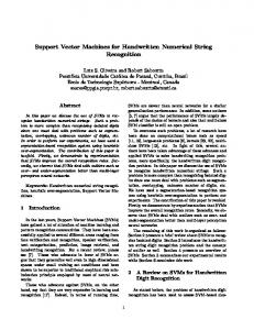
V. APPLICATION EXAMPLES The above proposed method and procedure have been applied to the application of many different types of power devices and drives. Three applications examples are presented here. A. Brushless dc Motor Drive A brushless dc motor with three phase windings is simulated using the 2D FE model. The rating of the prototype is 900 W at 24 V; it has 11 pole pairs, 24 stator slots, and operates at 136 rpm. The permanent magnet embedded in the motor is Nd-Fe-B and the power electronic switching elements used in the converter are MOSFET. The motor is driven by the control strategy of two-phase-on excitation. The eddy current in the permanent magnet is taken into account in the solution by modeling the permanent magnet as a solid conductor in the electrical property. The computed steady-state flux distribution is shown in Fig. 1. The computed and measured stator phase currents are shown in Fig. 2 and Fig. 3, respectively, when the motor is fed from a PWM voltage inverter. It can be seen that the excellent agreement between the simulated and measured results is achieved.
Fig. 1. Flux plot of the blushless dc motor
Fig. 2. Computed phase current
Fig. 5. Reference voltages and a common triangular carrier wave Fig. 3. Measured phase current
B. PM Synchronous Motor Drive The next example is a 4 pole, 24-slot stator, 3 phases, 50 Hz, Y connected PM synchronous motor. The stator winding has 138 turns per phase in series and is fed by an ac-dc-ac PWM inverter as shown in Fig. 4. The three-phase reference voltages are compared with a common isosceles triangular carrier wave as shown in Fig. 5. The carrier frequency of the PWM inverter is 1200 Hz. and the modulation index is 0.7. As a result, the modulated waveform for one phase is shown in Fig. 6. When the motor is operated at a torque angle of 14.3 electrical degrees, the computed three-phase current waveforms together with the current profile in the dc link computed by using the 2D model are shown in Fig. 7. The corresponding torque response is shown in Fig. 8.
T1
T3
T5
D1
D3
D5
T4
T6
T2
D4
D6
D2
B A
+ -
vA
+ -
vB
+ -
Fig. 6. Generated PWM waveform
Fig. 7. Current waveforms fed by PWM
vC
C
Motor
Power Supply
FEM Region
Fig. 4. PM synchronous motor fed by an ac-dc-ac inverter Fig. 8. Torque response
C. Three-phase Power Transformer In this example, a 30kVA, 10kV/0.4kV three-phase power transformer is analyzed using the 3D model. The primary windings have 1689 turns per phase and are delta connected; the secondary windings have 39 turns per phase and are Y connected. The connection of the windings, rectifier and load circuit are shown in Fig. 9. In this case, the primary winding connection is realized by the embedded simple circuit coupling approach as described in section III. The connection of secondary windings, the rectifier and the load circuit are handled by external circuit coupling. Fig. 10 shows the plots of flux density in the core at two instances t = 0.008 s and t = 0.011 s, respectively. Fig. 11 shows the computed core loss versus time in the iron core. The core loss includes eddy current loss, excess loss and hysteresis loss. The hysteresis loss has taken minor loops of the magnetization curve into account. The details of core loss computation will be reported in a future paper. Fig. 12 shows the corresponding voltage output from rectifier, and Fig. 13 shows the profiles of the three-phase secondary winding currents. The small notches on the voltage output curve are caused by the on-off switching action.
D1 A
a
+ -
vB
B
b
vC
C
c
+ -
+ -
vA
Power Supply
D3
D5 L C
R
Transformer
Fig. 11. Computed core loss
D4
D6
FEM Region
Fig. 12. Output voltage from rectifier
D2
Load
Fig. 9. The connection of the windings, rectifier and load circuit
Fig. 13. Secondary winding currents
VI. CONCLUSION
Fig. 10. Flux density of the transformer
A general approach for coupling electrical machines with drive circuits has been presented. This approach provides useful tool to simulate motor drives based directly on physical models. The electric machine is modeled by using either the 2D or the 3D transient FEM. The FEM provides a
detailed and accurate representation of the field distribution and physics. Circuit equations are created based on tree/cotree graph and loop analysis. This algorithm together with an embedded schematic capture capability provides flexibility and permits arbitrarily connected external circuits to be analyzed. These field and circuit equations are coupled together and solved simultaneously step by step in time domain. The simulation results for the three application examples presented match available measurement data well. In addition to the circuit coupling as described above, the electromagnetic coupling approach presented here can also be extended to support thermal, mechanical, and hydraulic components. REFERENCES [1] [2] [3] [4]
[5] [6]
[7]
[8] [9]
[10]
[11]
[12] [13]
P.J. Leonard and D. Rodger, “Modelling voltage forced coils using reduced scalar potential method,” IEEE Trans. on Magn., Vol. 28, No. 2, pp. 1615-1617, March 1992. T. Dreher and G. Meunier, “3D line current model of coils and external circuits,” IEEE Trans. on Magn., Vol. 31, No. 3, pp. 1853-1856, May 1995. F. Piviou and A. Razek, “Finite element analysis in electromagnetic systems accounting for electrical circuit,” IEEE Trans. on Magn., Vol. 29, No. 2, pp. 1669-1675, March 1993. T.E. McDermott, Ping Zhou, J. Gilmore, and Z. Cendes, “Electromechanical system simulation with models generated from finite element solutions,” IEEE Trans. on Magn., Vol. 33, No. 2, pp. 1682-1685, March 1997. Kay Hameyer, Johan Driesen, Herbert De Gersem and Ronnie Belmans, “The Classification of Coupled Field Problems,” IEEE Trans. on Magn., Vol. 35, No. 3, pp. 1618-1621, May 1999. Nancy Mieko Abe and Jose Roberto Cardoso, “Coupling Electric Circuit and 2D-FEM Model with Dommel’s Approach for Transient Analysis,” IEEE Trans. on Magn., Vol. 34, No. 5, pp. 3487-3490, September 1998. N.A. Demerdash, J.F. Bangura and A.A. Arkadan, “A Time-Stepping Coupled Finite Element-State Space Model for Induction Motor Drives - Part 1: Model Formulation and Machine Parameter Computation,” IEEE Trans. on Energy Conversion, Vol. 14, No. 4, pp. 1465-1471, December 1999. J. Vaananen, “Circuit theoretical approach to couple two-dimensional finite element models with external ciruit equations,” IEEE Trans. on Magn., Vol. 32, No. 2, pp. 400-410, March 1996. P. Zhou, S. Stanton and Z.J. Cendes, “Dynamic modeling of three phase and single phase induction motors,” Proceedings of IEEE International Electric Machines and Drives Conference, Seattle, May 1999, pp. 556-558. J.P. Webb, B. Forghani and D.A. Lowther, “An approach to solution of three-dimensional voltage driven and multiply connected eddy current problems,” IEEE Trans. on Magn., Vol. 28, No. 2, pp. 1193-1196, March 1992. Ping Zhou, Gilmore, J., Badics, Z. and Cendes, Z.J., “Finite element analysis of induction motors based on computing detailed equivalent circuit parameters,” IEEE Trans. on Magn., Vol. 34, No. 5, pp. 34993502, September 1998. Z. Ren, P. Zhou, and Z. Cendes, “Computation of current vector potential due to excitation currents in multiply connected conductor,” in ICEF 2000, Tianjan, China, September 2000. N. Deo, Graph Theory with Application to Engineering and Computer Science, Prentice-Hall, 1974.