ISSN 1063-7850, Technical Physics Letters, 2018, Vol. 44, No. 2, pp. 164–166. © Pleiades Publishing, Ltd., 2018. Original Russian Text © A.I. Saifutdinov, B.A. Timerkaev, A.R. Ibragimov, 2018, published in Pis’ma v Zhurnal Tekhnicheskoi Fiziki, 2018, Vol. 44, No. 4, pp. 74–79.
Numerical Simulation of Temperature Fields in a Direct-Current Plasma Torch A. I. Saifutdinova, b*, B. A. Timerkaevc, and A. R. Ibragimova a
Kazan Federal University, Kazan, Tatarstan, 420008 Russia Petersburg State University, St. Petersburg, 199034 Russia c A.N. Tupolev Kazan National Research Technical University, Kazan, Tatarstan, 420111 Russia *e-mail:
[email protected] b St.
Received August 7, 2017
Abstract—Thermal characteristics of a direct-current plasma torch have been studied in the framework of numerical simulations of temperature fields in a plasma channel, cathode, and anode. It is established that the temperature of the operating cathode surface exceeds the melting temperature of the cathode material. DOI: 10.1134/S1063785018020281
Plasma torches of various types have been widely used for many years, in particular, in metallurgy for hardening metal surfaces, plasma deposition of coatings, obtaining fine powders, cutting metals, etc. [1– 3]. The variety of applications determines wide range of requirements to the properties of plasma torches. A long operation life of a plasma torch is directly related to that of its heavy-duty elements, in particular, electrodes. The thermal state of the surface and the magnitude and character of erosion of thermionic cathodes in high-current plasma torches determine their performance characteristics and working life. The interacting system of electrode and near-cathode plasma is a complicated object of investigation that is characterized by strong spatiotemporal inhomogeneity. Inhomogeneous temperature fields on the surface of thermionic cathodes can lead to the appearance of local overheated zones, evaporation of the cathode material, its cracking and fracture, and a number of other processes and phenomena determining the working life of cathodes. For these reasons, spatiotemporal analysis of temperature fields on the surface of cathodes generating high-current electric arcs is a topical task. Numerous investigations have been devoted to determination and optimization of plasma torch characteristics. However, despite the considerable progress that has been made in modeling direct-current plasma torches [4– 8], the temperatures of the inner surfaces of plasma torch electrodes are still typically set to be constant and their inhomogeneous heating due to processes at the boundary of arc plasma is ignored. The present work was devoted to numerical simulation of the main characteristics of dc plasma torches, in particular, self-consistent determination of the dis-
tribution of temperature fields in electrodes. The model was based on the system of Navier–Stokes equations (including the equation of continuity, equations of motion, and equation of heat transfer in the plasma jet) supplemented by the system of Maxwell equations for the electric and magnetic fields, the differential Ohm’s law, and the equations of heat balance in a metal cathode and anode:
∂ρ + ∇(ρV ) = 0, ∂t ρ ∂V + V ⋅ ∇ V = j × B ∂t − ∇ ⎡P + 2 μ(∇ ⋅ V )⎤ + 2∇(μS ), ⎢⎣ ⎥⎦ 3
(
(
)
)
ρc p ∂T + V ⋅ ∇T − dP = ∇(λ 2∇T ) dt ∂t 5kB j ⋅ ∇T − Qrad , + j×E + 2e ∇(σ∇ϕ) = 0, E = −∇ϕ, j = σE,
∇ A = −μ0 j, 2
B = ∇ × A,
(1)
(2)
(3)
(4)
⎛ ∂T ⎞ (5) ρc,ac pc, pa ⎜ c,a ⎟ = ∇(λc,a ⋅ ∇Tc,a ). ⎝ ∂t ⎠ Here, ρ, ρc, and ρa are the densities of the gas and the cathode and anode materials, respectively; t is the time; V is the velocity vector; B is the magnetic-induction vector; P is the gas pressure; μ is the dynamic viscosity; cp, cpc, and cpa are the heat capacities of the gas, cathode, and anode, respectively, at constant pressure; T, Tc, and Ta are temperatures in the plasma channel, cathode, and anode, respectively; E is the
164
NUMERICAL SIMULATION OF TEMPERATURE FIELDS
165
Table 1. Boundary conditions Boundary
Boundary conditions*
Entrance of plasma channel
T = T0,
∫ ρ(V ⋅ n)dbcdS
= m,
j ⋅ n = 0,
A×n = 0
∂Ω
Cathode working surface
T = Tc ,
V = 0,
A×n = 0
(8)
Anode working surface
T = Ta,
V = 0,
A×n = 0
(7)
∇T = 0,
Outer boundaries of plasma channel Outer boundaries of cathode and anode
P = P0,
T = T0,
∫
∂Ω
j ⋅ n = 0,
j ⋅ ndS |c = I 0,
A×n = 0
ϕ|a = 0
*∂Ω is the channel input section of plasma-forming gas inflow, dbc is the boundary of plasma-forming gas inflow, m is the mass flow rate of plasma-forming gas, dS is the elementary section of the channel in which the gas flow rate is constant, n is the normal vector, P = P0 is the output-gas pressure, and I0 is the plasma torch arc current.
electric-field strength; λ, λc, and λa are the thermal conductivities of the gas and the cathode and anode materials, respectively; σ is the specific electric conductivity; ϕ is the electric potential; A is the vector potential of the magnetic field; μ0 is the magnetic permittivity of vacuum; j is the total current density; kB is the Boltzmann constant; e is the electron charge; and Qrad is the temperature-dependent specific radiation power. The computational region consisted of three domains: cathode, anode, and plasma channel. Boundary conditions are presented in Table 1. Let us consider in more detail the boundary conditions at interfaces between the arc plasma and electrodes. 1. The boundary between the arc plasma and anode obeys the following condition [5]:
[−(λa ⋅ ∇Ta ⋅ (−n))]anode
(6)
− [−(λ ⋅ ∇T (−n))]plasma = |j ⋅ n|φa − εσBT 4,
which shows that the normal flux of heat to the anode includes components due to the heat conductance from plasma, electron bombardment, and cooling by radiation from a solid. Here, φa is the electron work function of a metal anode and σB is the Stephan– Boltzmann constant.
and ji and je are the ion and electron currents, respectively, defined as
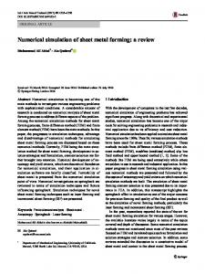
⎧ jr , (|j ⋅ n| − jr ) > 0, jc = ⎨ ⎩|j ⋅ n|, (|j ⋅ n| − jr ) < 0, (8) ⎛ −eφe ⎞ 2 ji = |j ⋅ n| − je, jr = ArT exp ⎜ ⎟, ⎝ kBT ⎠ where Ar is the Richardson–Dushman constant and φe is the effective work function of thermoelectron emission. Numerical experiments were performed with an F4 Solzer Metco dc plasma torch with tungsten cathode, copper anode, and argon as the working gas. Figure 1 shows the temperature distributions calculated at various moments of time for a plasma-forming gas-consumption rate of 2 g/s and arc-discharge current of 300 A. As can be seen, the time of established plasmaflux formation is about 0.004 s. Figure 2 presents the fields of temperature and plasma-jet velocity (in the arc-plasma channel and near the cathode and anode) at t = 1 s in a plasma torch operating under the same conditions. It can be seen that the gas temperature in
t = 0.001 s
2. The normal discontinuity of heat flux at the boundary between arc plasma and cathode is described taking into account the heat transfer from the arc to the cathode, heating by ion flux, and cooling by thermoelectron emission and radiation from solid according to the Stephan–Boltzmann law:
[−(λc ⋅ ∇Tc ⋅ (−n))]cathode − [−(λ ⋅ ∇T (−n))]plasma = ji ϕi − jeφc − εσBT , 4
(7)
Vol. 44
No. 2
t = 0.004 s 0.5
1.0
1.5
2.0
2.5
4
T, 10 K
Here, ϕi the ionization potential of the buffer gas, φc is the effective work function of the cathode material, TECHNICAL PHYSICS LETTERS
t = 0.002 s
2018
Fig. 1. Dynamics of plasma torch-jet temperature-field development.
166
SAIFUTDINOV et al.
(a)
0.5
0.5
1.0
300
1.0
1.5 T, 104 K
1.5
2.0 2.5 Tc, 103 K
350
400 Ta, K
2.0
3.0
450
2.5
3.5
4.0
500 (b)
from the working surface of the cathode, the temperature drops by more than 800 K due to effective cooling of the outer side. The cathode surface temperature increases with the arc discharge current and reaches 4200, 4400, and 4500 K at plasma torch currents of 400, 500, and 600 A, respectively. The depth of metal fusion at 600 A is about 1.8 mm. In concluding, we have formulated a model of a dc plasma torch with allowance for the self-consistent heating of electrodes. The results of numerical model calculations showed for the first time that the temperature of the working cathode surface exceeds the melting temperature of cathode material (tungsten). The results can be used in investigations of the erosion of electrodes in modern plasma torches. Acknowledgments. This work was supported in part by the Russian Foundation for Basic Research, project no. 16-38-60187 mol_a_dk. REFERENCES
0
100
200
300 V, m/s
400
500
Fig. 2. Distributions of (a) temperature and (b) plasma-jet velocity at t = 1 s in plasma torch operating at an arc discharge current of 300 A.
the plasma channel reaches up to 25000 K and the working surface temperature of the tungsten cathode exceeds its melting point and reaches a level of about 4000 K, while the copper-anode surface temperature at the arc spot is slightly above 500 K. It should be noted that the cathode-surface temperature reaches the melting temperature of tungsten already at t = 0.3 s. In addition, it is worth noting a sharp change in the temperature field profile along coordinate z near the cathode arc spot. Indeed, at a depth as small as 1 mm
1. M. F. Zhukov, I. M. Zasypkin, A. N. Timoshevskii, B. I. Mikhailov, and G. A. Desyatkov, Low-Temperature Plasma, Vol. 17: Electric Arc Thermal Plasma Generators (Nauka, Novosibirsk, 1999) [in Russian]. 2. I. A. Glebov and F. G. Rutberg, High Power Plasma Generators (Energoatomizdat, Moscow, 1985) [in Russian]. 3. V. Ya. Frolov, D. V. Ivanov, and M. A. Shibaev, Tech. Phys. Lett. 40, 676 (2014). 4. C. Chazelas, J. P. Trelles, I. Choquet, and A. Vardelle, Plasma Chem. Plasma Process. 37, 627 (2017). 5. C. H. Chang and J. D. Ramshaw, Plasma Chem. Plasma Process. 13, 189 (1993). 6. H. P. Li and X. Chen, Plasma Chem. Plasma Process. 22, 27 (2002). 7. K. Ramachandran, N. Kikukawa, and H. Nishiyama, Thin Solid Films 435, 298 (2003). 8. J. P. Trelles, C. Chazelas, A. Vardelle, and J. V. R. Heberlein, J. Therm. Spray Technol. 18, 728 (2009).
TECHNICAL PHYSICS LETTERS
Translated by P. Pozdeev
Vol. 44
No. 2
2018