general analytical solution to the problem of unconfined unsteady flow described ... solutions, on the other hand, are available in both explicit and implicit forms ...
INTERNATIONAL JOURNAL FOR NUMERICAL METHODS IN ENGINEERING, VOL. 15, 1643-1657 (19801
NUMERICAL SOLUTIONS FOR UNSTEADY FLOW IN UNCONFINED AQUIFERS V. GUVANASEN? AND
R. E. VOLKERS
Department of Civil and Systems Engineering, James Cook University of North Queensland, Australia
SUMMARY Two numerical methods for solving the problem of unsteady flow in unconfined aquifers are studied. They are an explicit finite difference method (FDM), and the finite element method (FEM). The FEM is further subdivided into three schemes: vertical displacement approach, explicit scheme (FEMl), normal velocity approach, explicit scheme (FEM2), and vertical displacement approach, implicit scheme (FEM3). Results from the above methods are compared with experimental results from a sand box model. Various factors affecting the accuracy and numerical stability are investigated. Results indicate that, for a similar degree of accuracy, the FEM requires less computational effort than the explicit FDM. Amongst the three FEM schemes, FEM3 appears to be most attractive as it is the most stable and economical of the three schemes compared.
INTRODUCTION It is well known that saturated flow theory describing unsteady flow in unconfined aquifers involves potential theory with a nonlinear transient boundary condition at the free surface. A general analytical solution to the problem of unconfined unsteady flow described by the above theory is not presently available. Two distinct numerical methods of solving the flow equation are discussed here, the finite difference method (FDM) and the finite element method ( E M ) . Workers including Todsen,’ Amar’ and Singh3 reported successful use of the finite difference method in drainage and recharge problems. Application of the finite element method (FEM) to the problem of unsteady ,~ et al.,’ Neuman and flow in unconfined aquifers has been presented by F r a n ~ e Taylor Witherspoon6 and The FDM has only been applied in an explicit type of formulation and for this case the stability and factors affecting accuracy have been rigorously explored for drainage problems.’ FEM solutions, on the other hand, are available in both explicit and implicit forms because of the flexibility of the FEM in handling problems with complex geometry and boundary conditions. However, the study of the stability and factors affecting accuracy of the various FEM solutions to the problem of unsteady flow has not been carried out in detail. This paper compares the stability, computational requirements, and accuracy of various FDM and FEM models, so that selection of appropriate models may be facilitated. Results presented in this paper are restricted to a homogeneous isotropic porous medium with similar boundary conditions to those of Figure 1,for which experimental results are available for comparison purposes. t Research Scholar.
t Senior Lecturer.
Received 28 August 1979 Revised 1 February 1980
0029-5981/80/1115-1643$01.00 @ 1980 by John Wiley & Sons, Ltd. 1643
1644
V. GUVANASEN AND R. E. VOLKER
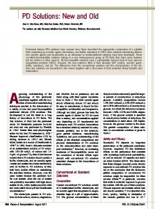
Figure 1. Definition sketch
THEORETICAL BACKGROUND The continuity condition in groundwater flow can be tensorially expressed as: lo aui -- 0, axi
i = 1,2,3
where ui is the velocity in the ith direction, and xi the Cartesian co-ordinate. In the work that follows, spatial co-ordinates in some parts of the derivation are given in the tensorial form, as above, for brevity. Wherever x, y, z are used they are taken to be equivalent to xl, x2, x3, respectively, with x3 and z directions vertically upwards. Using Darcy’s law for isotropic porous media the above equation can be written thus:
or for homogeneous media the above equation is reduced to
where K is the hydraulic conductivity, and h the piezometric head. Boundary conditions are normally of the types below: (i) Constant head boundary:
h=H, where H, is the head on the boundary. (ii) Prescribed flux boundary:
(3)
UNSTEADY FLOW IN UNCONFINED AQUIFERS
1645
where qn is the flux normal to the boundary (positive inwards), and li the component of unit outward normal to the boundary. (iii) Seepage surface: h=z
(5)
h=H=z
(64
(iv) Free surface:6
and
(R-eesr
")
i 3 = ~ ah -ii axi
where Be is the effective porosity at the free surface, R the infiltration rate, and, H the elevation of the free surface above reference datum. The term 'effective porosity',*' 8, refers to either 'fillable porosity' in the case of rising free surface or 'drainable porosity' in the case of receding free surface. Equation (6b) can also be written for isotropic media as'
NUMERICAL SCHEMES Four numerical schemes are investigated in this paper, one finite difference (FDM) scheme and three finite element (FEM)schemes. For simplicity the following formulations are intended for two-dimensional problems; however, extension to three-dimensional cases is straightforward and does not involve any new concept.
Finite differencemodel The details of this type of numerical model have been given by Todsen' and Amar,' and are only briefly presented here. A typical finite difference grid network is shown in Figure 2. The procedure is as follows: (1) The position of the free surface being initially known, the value of h at any interior node i, j , is calculated iteratively using the following equation:
in which rn refers to the iteration number and j3 is the Successive Over-Relaxation (SOR) accelerating factor. For grid points in the vicinity of the free surface, such as node k, 1 in Figure 2, the following equation is employed:
where q and 6 are diagrammatically defined in Figure 2.
1646
V. GUVANASEN AND R. E. VOLKER
A x = A z = Ad Figure 2. Typical finite difference grid
It should also be noted that the truncation error is of the order of O(Ad2)in equation (8)and of the order of O(Ad) in equation (9), where Ad is the grid size. The iteration process is continued until the residual errors at all interior grid points satisfy the following condition:
M ~ i . j I h ~- "h
~ I ~ f m a x
(10)
where fmax is a maximum preassigned residual error. (2) The position of the free surface at time t is projected to that at time t + Ar using equation (7), which is written in the finite difference form:
in which dh/dzlZ,, is evaluated from interior grid points using Taylor's expansion, and Ar is the time increment. At the boundary where aH/dx is specified, dHi/dx is calculated with the aid of an exterior node. In the case of a seepage surface, it is not convenient to use equation (11)and the exit point is located through a linear extrapolation from two interior nodes adjacent to the exit point. Finite element models
Let the distribution of piezometric head be approximated by
h=i=
Ni(xj)hr(t) r=i
UNSTEADY FLOW IN UNCONFINED AQUIFERS
1647
where NI is the basis function at node I, and hr the piezometric head at node I from FEM solution. IJsing the Galerkin technique one can state that
from which, through Green's theorem, one obtains
where A is the area over which integration takes place, and S the boundary portion over which integration takes place. In this paper, three FEM schemes are presented, their differences depending on how equation (14) is solved.
Scheme 1 (FEMI).The solution is divided into two parts-the diagnostic and the prognostic parts-similar to that for the FDM model. The solution to the diagnostic part is achieved through equation (14),in which only equation (6a) ( h = H = z ) is utilized at the free surface. On combining the contributions from all elements, the resultant set of simultaneous equations can be written thus:
where
Having obtained the values of piezometric heads from equation (15), the prognostic part which is described by equation (7) is then solved. Let H be approximated in the form n
H
= A = 1I N , ( x ) H , ( ~ )
(16)
where NI is the basis function of line elements on the free surface. Applying the Galerkin technique to equation (7) using equation (16), one obtains
where I'is the length along which integration takes place, and the values of ah/az are calculated from elements having at least one side on the free surface. Using an explicit finite difference approximation for the time derivative, the resultant set of simultaneous equations can he written thus:
[$1'
({H}'+Ar - { H } r= { U}'
1648
V. GUVANASEN AND R. E. VOLKER
where
The solution proceeds by first solving equation (15) to give the piezometric distribution, then equation (18) is solved to give the free surface location in the next time step (Figure 3). This scheme can also be described as a FEM version of its FDM counterpart described earlier.
New nodal
---.___
--------___New free
----/.-
surface
---. --.. ----.
Figure 3. Movement of the free surface FEMl
Scheme 2 (FEMZ).This scheme is essentially similar to FEM1, the difference being only in the prognostic part. The solution of the diagnostic part is identical to that of FEM1. The prognostic part is solved as follows. Equation (6b) can be rewritten as un = -1- ( R I ~ - Kah -I~)
axi
0e
where vn is the velocity of the free surface in the direction normal to the free surface. Only linear triangular elements are used here and so u,, is determined by first evaluating horizontal and vertical velocity components for each free surface element and then resolving in the n direction. The movement of a position vector P of a point on the free surface in the direction normal to the free surface is calculated by p'+At =
p'
= u:,
. At
(20)
Various investigators, including F r a n ~ eemployed ,~ equation (20) to move nodes at the free surface to their new locations. The new free surface was formed by fitting a surface to the points at their new locations so that nodes on the old free surface could be vertically projected to the new free ~ u r f a c eIn . ~ this work the new free surface is formed by moving the midside of each element at the free surface using equation (20). The nodes on the free surface are then vertically shifted to the new free surface which is described by a cubic spline function (Figure 4). Scheme 3 (FEM3).In this scheme, equation (14) is solved by incorporating conditions (6a) and (6b) together in an iterative solution process instead of alternately as in FEMl and FEM2.
1649
UNSTEADY FLOW IN UNCONFINED AQUIFERS
New nodal
--
( position
Old free surface
node
Figure 4. Movement of the free surface FEM2
On applying condition (6b) at the free surface to equation (14) one obtains
-Iso
N , Ka6 z 1; d S = 0
(21)
where SF is the free surface boundary, and Sothe flux-type boundary. Combining contributions of all elements leads to the following set of simultaneous equations:
rw{$}+ { F )= o
[DX~ +) where
Drj = C
aNI arv, -dA axi axj
KA
or
ah NIK- 1; d S on the flux-type boundary. 0
ax;
Equation (22) is recast in the form
which is rearranged to give
where A is the time-stepping weighting factor.
(22)
1650
V. GUVANASEN AND R. E. VOLKER
The system of simultaneous equations represented by equation (23) is solved iteratively until the condition of convergence (24)
maxIhI-zI~f,,, I
is satisfied at all nodes along the free surface, where fmax is the preassigned maximum allowable error. After each iteration, the heights of nodes at the free surface are adjusted according to the following expression: Znew
= L i d +- w(hnew- ZOICI)
(25)
where w is the convergence accelerating factor. Iteration is repeated until proviso (24) is achieved.
RESULTS AND DISCUSSION Results from various numerical schemes are compared with experimental results from a sand box model which simulates a recharge condition similar to that shown in Figure 1. Because of symmetry only one half needs to be considered. In Figure 1 the flow equation is subjected to the following conditions: h=a,,
t=0,
ah -=o ax
h
ZE[O,QO]
x=o
x
=UO,
=B,
h=z,
x=B,
R =Po,
x
=o,
XE[O,B],
E [O,
z E [O, a03 ZE[UO,H]
L]
XE[L,B]
where a . is the initial saturated depth, Po the rate of infiltration from recharge basin, L the basin half-width, and B the aquifer half-width. The diagrammatical definition of the above variables is exhibited in Figure 1. Experimental details are given elsewhere.” Details of various parameters used are shown in Table I. The porous medium (sand) is assumed to be homogeneous and isotropic. Prior to comparing the solutions given by the FDM, one has to investigate various parameters affecting the performance of the model, namely: residual error, SOR accelerating factor, types of initial guess, requirement of smoothing, and stability. Table I. Values of parameter used
360
300.0
6000.0
15.6
0.2988
1651
UNSTEADY FLOW IN UNCONFINED AQUIFERS
Investigation of the above parameters was carried out by Todsen' for drainage problems. Results of recharge problems reported by Amar' and Singh3 did not include such a study. It is therefore of interest to carry out a preliminary investigation of the influence of the above parameters for the recharge problem. The optimal SOR accelerating factor, B in equation (8),was found to be between 1.5 and 1 -6 from an iterations vs. p plot as shown in Figure 5. The residual error was found to play an important role in the accuracy of the solution. It was found that if fmax/Ax was too large, the solution would be damped as shown in Figure 6, in which results are displayed as dimensionless
25
I
5'
1.6
1.L
1.8
B Figure 5. Plots of iterations/tirne step vs. p
f
0'
160
t'
320
In, x ' A x
L80
Figure 6. Plots of dimensionless piezometric head h" vs. dimensionless time f' showing effects of f,,,,./Ax solutions: z / a o = 0.14; h" = ( h -ao)/(aop');I' = fKao/(8,L2);p ' = PoL2/(Kao2)
in FDM
1652
V. GUVANASEN AND R. E. VOLKER
piezometric head h ” = (h -ao)/(aop’) and dimensionless time r’ = tKu0/(f3,L2), where p ’ = P&2/(Kao2).By numerical experiments it was found that the upper limit of fmal/Ax for this problem was (compare with by Todsen’). Todsen’ also suggested a formula for an initial guess of piezometric heads at the beginning of each time step; however, it was found in this study that it was better to employ the piezometric head distribution at the end of the previous time step as an initial guess. The number of iterations required employing this initial guess was found to be much less than that required when Todsen’s formula was used. Todsen’ also reported successful use of a smoothing block on the free surface to eliminate aliasing error or misinterpretation of wavelengths due to the nonlinear nature of the equation. Figure 7 shows that smoothing gives misleading results because the dimensionless piezometric heads obtained at large x / L from the solution incorporating smoothing, rise sooner than both experimental results and those without smoothing. Details of smoothing are given b y Todsen.
’
6
2
Figure 7. Plots of dimensionless piezometric head h” vs. dimensionless time r‘ showingeffectsof smoothing ( z / a o = 0.14)
The size of discretization also exerts an influence on the accuracy and stability of numerical models. By numerical experiments it was found that the solution was stable provided that KAt -