CEAI, Vol. 8, No. 1, pp. 22-32, 2006
Printed in Romania
ON AGENT BASED MULTI-ROBOT COORDINATION IN A FLEXIBLE MANUFACTURING SYSTEM Doru Panescu, Gabriela Varvara
“Gh. Asachi” Technical University of Iasi, Faculty of Automatic Control and Computer Engineering, Department of Automatic Control and Applied Informatics, Bd. D. Mangeron 53A, Iasi, 700050, Romania E-mail :
[email protected];
[email protected]
Abstract: The fields of multi-robot and multi-agent systems represent active and topical research themes. Their results can be important for several areas, this paper considering the industrial application. The possibility to solve through robot cooperation an assembly process is discussed, the proposed approach using an agent based solution. Some theoretical and practical issues on robot coordination are presented, the architecture being tested in a flexible manufacturing system with two industrial robots. Keywords: multi-robot systems, multi-agent systems, planning, flexible manufacturing systems, temporal reasoning.
1. INTRODUCTION The multi-agent and multi-robot systems are two research fields that possess certain convergence issues. Both refer to a distributed approach, often complex systems are involved and an important autonomy is a must. Meanwhile neither of the two got definite solutions, nor the application of software agents in Robotics had a great impact till now. That is why it is worth investigating how the current multi-agent systems technology can be used in multi-robot systems. As a brief definition, a multi-agent system can be seen as a structure composed of multiple, interacting agents [12]. The key issues in this
statement are the words agent and interaction. As about the agent, this is the best described by its characteristics; the most often referred are: autonomy, reactivity, pro-activeness, communication abilities, mobility, rationality and social ability [3], [12], [13]. All these are to be related so that an agent should be able to interact with its environment, in a goal based fashion, according to a perceive, reason and act cycle [12], [13]. From this point the connection with Robotics is easy to make: a robot is a technical system supposed to replace a human operator in solving tiresome, difficult and/or dangerous tasks, exhibiting exactly the above mentioned agent characteristics and operating under the same before mentioned cycle.
CONTROL ENGINEERING AND APPLIED INFORMATICS
23
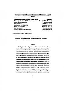
Cell 1 8 7 Common working area of the robots
10
1
3
5 9 6
4 2 Cell 2
Fig. 1. The flexible manufacturing system considered for experiments
8.
IRB
1. IRB 1400 industrial robot (R1), 2. IRB 2400 industrial robot (R2), 3. Machine tool, 4. Computer vision system, 5. Conveyor, 6, 7. Storage devices, 1400 robot controller, 9. IRB 2400 robot controller, 10. Assembly table concerns
The difference between a robot and an agent mainly the appearance of the two: a robot is always a physical system while an agent may be only a software entity. From its more complex actuation ability it results the greater impact on its environment that the robot should be capable to produce when compared with a software agent. In a brief assertion, a robot can be always seen as an agent (the only exceptions are the very simple manipulators repeating a single sequence of actions and with little sensorial endowment), while an agent can be a robot only when possessing definite physical sensorial and action sub-systems. Another link between multi-robot and multiagent systems is the nowadays challenge for Robotics to enlarge its application area by the use of robot teams instead of single robots [15]. The term of multi-robot system concerns an interdisciplinary field, covering besides the specific Robotics issues (like path planning and control for collision avoidance [9]), subjects on robot coordination and communication. These last points have already been analysed in
Distributed Artificial Intelligence, mainly into the framework of multi-agent systems, which further explains the connection made by this contribution. A significant problem for the research in multirobot systems is the possibility to assess the developed approach into a real environment. From this point of view, the proposed test-bed is shown in Fig. 1. Though the respective equipment can be used as a classical flexible manufacturing system, it can be also considered as a multi-robot system. This is justified by the following points: • There is a common working area of the two robots, above and in the vicinity of the assembling table (see Fig. 1), that creates the possibility of solving in cooperation an assembly goal. • The two robots can communicate each with the other. • They can be involved in solving common goals, which should suppose taking decisions on common resources use (e.g. the parts for assembly, the conveyor).
24
CONTROL ENGINEERING AND APPLIED INFORMATICS
Besides the two ABB industrial robots, type IRB 1400 and IRB 2400, named R1 and R2 in the following, the manufacturing system contains a machine tool, a conveyor and a computer vision based inspection system. The multi-robot solution for different assembly goals can vary in accordance with the way the raw and processed parts are present in the storage devices near the two robots, and the order the two robots are involved in assembly. In this way some specific coordination mechanisms are needed and the agent based approach is presented in the next paragraphs. After discussing a few specific elements on the agent based approach for a multi-robot system, the focus is on establishing certain coordination issues based on the relation between the time model of the agent activities and the structure of the goals; some aspects of the implementation are also presented.
design and implementation of an agent based solution in multi-robot systems.
2. SOME ASPECTS OF THE BDI AGENT BASED DESIGN FOR MANUFACTURING MULTI-ROBOT SYSTEMS The field of multi-agent systems is quite new and thus there is no general methodology for an agent based design approach. Instead, several specific schemes were developed, more frequently being referred: MaSE, Gaia, Prometheus, [2], [5], [11], [13]. When these are analysed in order to be used in a multirobot system, one may find some specific aspects and drawbacks. The multi-robot systems may vary, being composed of homogeneous robots or not, with various degrees of autonomy and sensing capabilities. Another aspect that can be considered the most important for distinguishing an agent based approach of the multi-robot systems refers to the environment characteristics. The robot based flexible manufacturing systems and respectively the mobile robots of a robot soccer environment are two limit examples [8], [11]. Thus, when comparing these two situations according to a multi-agent system environment classification [13], one discovers that the first case is towards the easiest conditions (accessible, deterministic, static and discrete), while the second is almost at the opposite limits. The present research tries to mediate between the various possibilities, in order to get some general elements for the
The various agent based approaches imply some specific software architecture. One of the most used, for purposes like military, commerce or entertainment applications is the BDI (Belief-Desire-Intention) architecture [10], [12]; it can provide certain advantages when utilized in manufacturing. One important point is the way the BDI scheme can bring about the necessary bias between the proactive and reactive components necessary for a multiagent system implied in production. To clarify this, it is to notice how the key issues of the BDI architecture are carried out in such an application. Without giving all the details of the designing phase (see also [5], [10], [11], [12]), agents have to manage with several entities: beliefs, intentions, desires, and plans. The beliefs collection provides an agent certain means to handle the interaction with its environment (which includes the agent itself, the other agents, and the user that should provide the goals, too). First the sensorial information conducts the agent towards formulating beliefs on the present state of its environment. Moreover, a belief is supposed to be more flexible than the usual preconditions used in classical pla nning or the state conditions in finite automata, and it is expected to create more possibilities, as going beyond the first order predicate logics. For example, the agent corresponding to the robot R1 may believe that a part is on the conveyor after it was informed by the robot R2 that it dropped that part on the conveyor. By making use of this belief the robot R1 can include the part in its plans, supposing it can get the respective part after a corresponding action. Though sometimes beliefs are only related with the sensorial information, in the proposed approach they are also associated with the goals. For example the robot R2 may believe that it has to solve the goal of supplying a part, and it will release this belief when the computer vision system will provide the information on the presence of the respective part in the storage device (this can be supplied without the robot R2 interaction). In this way a more opportunistic behaviour is obtained for the manufacturing system. The beliefs are to be updated according to the sensorial information available to the agent (the percepts – see Fig. 2) and in our case according to the
CONTROL ENGINEERING AND APPLIED INFORMATICS
set of goals, too; it is supposed that for a manufacturing system the goals are continuously received by the multi-agent system. Taking into account the current beliefs the agent is able to generate its desires. These are the agent’s options in achieving the goals. As generally known for an agent based solution [10], the desires must be consistent with both the present beliefs and intentions. After a further refinement step, the intentions are got from desires through an opportunistic filtering mechanism – see Fig. 2. This can be understood because the intentions represent the last phase before the agent’s action issuing. The intentions refer to the course of actions that the agent can consider and which are progressively refined until they correspond to elementary actions that it can put into practice. The intentions are to be obtained from desires, what makes the necessary connection with the goals. Moreover, as mentioned above the transformation of desires in intensions must be opportunistic, taking into account the changes in the environment. Percepts
Goals Beliefs
Desires
25
intentions and then their conversion in actions constitute the agent planning process. Besides offering the choice set for the action selection, the agent can use intentions to filter future planning, based on the necessity to maintain the consistency of its knowledge base. For example, the agent corresponding to the robot R2 while having the intention to discharge the conveyor, based on the belief that this is full, will not consider the intention to place a part on the conveyor. On the other hand, intentions must persist. The robot R2 will not leave its intention to assemble a product until either it succeeds to do this, or knows (believes) that the respective product was assembled in another way. It is clear that reactivity should influence this process. In the above example, the agent attached to the robot will drop the mentioned intention when it has the feedback that the product has been assembled by the other robot. Thus, an agent has to cyclically revise its intentions and to find the correct balance about this process, namely to establish a right frequency for the reconsideration of intentions. In the case of the considered manufacturing system intensions are to be re-computed only in the case of an event that is influencing a goal. This means that a beliefs versus goals comparison should determine the corresponding moments. It is supposed that such a result is quite general, i.e. it can be applied to any computer aided manufacturing system; further comments can be made after considering some additional theoretical issues.
Opportunistic Filter
Intentions (Plan schemes)
Actions Fig. 2. The adapted BDI agent architecture
Intentions are to be smoothly tuned in order to get the right bias between the reactive and proactive characteristics. Through the goal influence, they can determine the necessary proactive feature. They are part of the planning phase; in fact, the desire transformation in
3. A POSSIBLE CONECTION BETWEEN THE BDI ARCHITECTURE AND THE BRANCHING TIME MODEL As about the logical background of the BDI model, the predicate logic, its extension, namely the modal logic and the branching time model are to be considered [1], [6], [10]. It is important to observe the practical implications of these theoretical aspects for manufacturing systems planning and controlling. Referring only to temporal reasoning, the branching time model considers a state space approach with the states arranged in a tree that branches into the future (each branch is called a world) [1], [6]. In this way the agent is capable to consider
26
CONTROL ENGINEERING AND APPLIED INFORMATICS
several future evolutions, named possible worlds.
plans and actions. The link between the desires and the agent actual actions is provided by its intentions. In the case of a manufacturing system, where the robots are supposed to cooperate, the goals are the elements to determine the desires of the agents; that is why the next paragraph is dedicated to further considerations on goal driven agent based systems. Intentions should provide the means for a goal solving. For example, if the robot R1 has been provided the goal to obtain a processed part of a certain type, and the robot has the belief that a raw part is present in the nearby storage device, then it reaches the intention to feed the machine tool in order to obtain the necessary processed part. The way the intentions are obtained from the agent desires and beliefs can be something similar to conventional planning [1], [6] or to the use of certain a-priori devised planning schemes [5], and the branching time model supports both approaches.
As an example, Fig. 3 presents such a model for the considered system. The starting moment is t0 when the agent corresponding to the robot R1 knows that property Pc holds – a part is on the conveyor, according to the information provided by its sensorial system. The various paths correspond to different actions executed by the robot R1: a 1 – picking up of a part from the storage device, a 2 – picking up of a part from the conveyor, a 3 – transfer of a part from the storage device to the assembly table, a 4 – feeding of the machine tool, a 5 – wait until the part is processed, a 6 – part transfer from the machine tool to the assembly table, a 7 – part placing on the conveyor, or to events independent of the robot: b – fall of the part from the conveyor. By making use of this representation the agent beliefs become statements possibly true – for example, at the moment t0 it may believe that a part is on the conveyor (which is indeed true, property Pc in Fig. 3), and may believe that this can still hold until some future moment, for example according to the path determined by the action a 2 . It is obvious from the model that this belief may become false in certain circumstances, e.g. when event b is happening. a3 a1 Pc t0
a1
a4
a5
a2
a6 a7
b Fig. 3. An example on the branching time model
For a manufacturing system the agent desires can be also considered statements possible true, but unlike the beliefs they strictly refer to future moments and to properties that can be determined by the agent activity. In the case of the proposed environment, the robot R1 may have several desires: to feed the storage device, to feed the machine tool, to unload the storage. It is clear that some desires can be in conflict each other or with some of the agent beliefs. From the planning point of view, desires can be considered potential inputs for the agent
4. ON THE GOAL ASSIGNMENT AND THE RELATED AGENT COORDINATION MECHANISM The starting point for the multi-robot as well as multi-agent system design should be an analysing phase, when the system goals are to be considered first. Various approaches attempt to solve the goal identification step by means of use cases or scenarios, and roles or functionalities [2], [5], [11]. It is to notice that for an agent based multi-robot system the following issues should be discovered: • The goal hierarchy – the way the goals are related to each other and their internal structure. In the case of a multi-robot based assembly (as the one in the environment described in Fig. 1) all the sub-goals are derived from assembly goals. The sub-goals can be classified in two categories: the ones to be achieved by a robot and respectively others to be solved by another device. According to Fig. 4, the manipulation for assembling, the machine tool/inspection system feeding/unfeeding and some auxiliary manipulation subgoals can be assigned to a robot, namely some of them to both robots and others only to one robot. In the considered case the auxiliary manipulation sub-goals refer to supplying and unloading of the storage devices and conveyor.
CONTROL ENGINEERING AND APPLIED INFORMATICS
27
Assembly goals
R1 R2
Manipulation for assembly sub-goals
Part processing sub-goals
R1
Machine tool feeding/un-feeding sub-goals
Inspection subgoals
R1 R2
Auxiliary manipulation subgoals
R2
Inspection system feeding/un-feeding sub-goals
Robot based goals
Non-robot goals
Cell transfer subgoals
Fig. 4. A multi-robot goal decomposition example
With respect to a multi-robot system approach, it is worth to further analyse these goals, because they may create a bottleneck for the whole system operation – at a certain instant a robot may be involved in a single goal achievement. When the goals and beliefs are analysed in accordance with the dependence they create on the agents of a multi-agent system [13], one discovers that all the possible situations can happen: a) independence – the robot R1 can solve the goal to feed the machine tool independently of the robot R2 when the necessary raw part is present in the storage device near the robot R1. b) unilateral – the robot R1 depends on the robot R2 in order to fulfil the goal of feeding the machine tool when the necessary raw part is not present in the storage device near the robot R1, but that raw part can be provided by the robot R2. c) mutual – the robots depend on each other with respect to solving an assembling goal, when each of them possesses one of the two parts that must be assembled. d) reciprocal – the robot R1 depends on the robot R2 with respect to obtaining the necessary raw part to be processed on the
machine tool, while the robot R2 depends on the robot R1 with respect to getting a processed part, that can be the same with the one implied by the current goal of the robot R1 (in fact this case satisfies the definition of mutual goals), or can be a different one. • The way the goals are assigned to the robots of the multi-robot system – this aspect can be handled as with the usual goal allocation to the agents of the multi-agent systems, based on an established coordination mechanism. The contract net protocol was used in the considered system [4], [7]. This is an interaction protocol for cooperative problem solving with agents. The goals are distributed based on a negotiation and communication procedure. In our system either the software agent which directly interacts with the user or an agent corresponding to a robot becomes a manager when having a goal that cannot be managed by itself. This is supposed to broadcast a message in the multi-agent system for the goal announcement, and then, through a negotiation mechanism, the goal fulfilment will be appointed to a contractor, namely the agent having the best capabilities to solve the goal. Some elements specific for the multi-
28
CONTROL ENGINEERING AND APPLIED INFORMATICS
robot systems still exist referring to the constraints robots exhibit regarding their interaction with the environment (e.g. a robot cannot solve a goal that implies a movement beyond its working area). Furthermore, the goal decomposition should be made till the actions to be achieved by individual agents, which means the robot actions in this case. In the proposed approach the goal division is made both by the manager and by the contractor, which is possible in the contract net mechanism (a contractor can further become a manager for some sub-goals [7]).
temporal and resource dependence. From the agent planning point of view it is easy to demonstrate that a resource dependence can be reduced to a temporal one. Namely, the typical case is when two or more agents depend on (have to use) the same resource and the situation is solved by establishing an order for their access to the respective resource.
• The goal solution must assure the consistency and completeness – these conditions can be checked as with the centralized systems (for example, as in the case of nonlinear planning [1]), but when using robots for industrial applications this tests can be simplified. Indeed, instead of trying to obtain a plan to solve a goal from scratch certain a-priori devised plan schemes may be considered and combined to solve a complex initial goal. This can be facilitated by a multiagent approach that makes use of a BDI architecture. A further discussion on the goals assignment can be useful in understanding the considered application. Often a manufacturing problem can determine several goals and/or a goal is divided in more sub-goals, which have to be solved in a distributed manner in the manufacturing system. Meanwhile, for a production process some scenarios suppose the necessity of a decision mechanism. A goal dependency analysis can guide the agent based solution with respect to the coordination and communication aspects. Thus one can take into account the following definition. Two goals can be considered independent if and only if the order in which the goals are solved does not matter for the problem they are derived from, and the solutions for the two goals does not imply the use of common resources. In such a case the agents solving the two goals do not need to exchange further information besides that on the goal fulfilment. Based on this definition an independence relation can be defined on the set of goals attached to a multirobot system and this relation possesses the properties of symmetry and non-transitivity [6]. When two goals are not independent these are to be considered from two points of view: their
When analysing the temporal dependence, two cases can be identified as being important for the agent communication mechanism. The simplest case is when two goals depend on each other, but so that no time overlap or interleaving exists between the actions solving the two goals. This means, for example, that the actions working out the first goal end before the first action of the second goal solution has to start. Such a situation is presented in Fig. 5; the goal of assembling a product determines two sub-goals: transferring of a part of type A to the assembly table and transferring & fixing of a part of type B. The first sub-goal can be assigned to the robot R1 (by the manager agent, which is a software agent, through the above mentioned contract net protocol), while the other should be solved by the agent corresponding to the robot R2. As the first sub-goal must be solved first, by only one agent – robot R1, and then the other subgoal can be entirely solved by the agent corresponding to robot R2, just a vertical message exchange is implied; the manager is awarding a contract to an agent and then the result of the goal fulfilment is sent from the contractor to the manager, as indicated by the arrows of the Fig. 5 – the number attached to the arrows indicates the message order. Software agent
Assemble a product of type 1 4
2 R1
1
Transfer a part of type A
3
R2
Transfer and fix a part of type B
Fig. 5. An example of non-overlapping goals
The other case corresponds to goals with a solution supposing an action overlapping or/and interleaving. Such a situation is presented in Fig. 6, when the goal of feeding
CONTROL ENGINEERING AND APPLIED INFORMATICS
29
Software agent Feeding of the machine tool
R1 1
R1
0 0
Load a raw part on the conveyor
Conveyor
0
0
2 Part transfer
7 Part transfer
R2
0
6
3 Identify the raw part
R2
Load the machine tool
Conveyor
4 Transfer the part to the CVS
R2
5 Transfer the part to the conveyor
Computer vision system (CSV)
R2
Part identification goal
Fig. 6. An example of goals with overlapping actions
the machine tool is decomposed in several subgoals by a software agent and the solution involves several agents with an action interleaving; for example, the conveyor actions referring to part transfer from one cell to the other (see Fig. 1) are interleaved with the actions of other agents. Even in this case the same message exchange scheme as above is still possible, wit h the manager agent receiving the messages on each sub-goal fulfilment and so being able to announce the next agent in the solution sequence. However, a better efficiency is obtained by combining vertical and horizontal message exchange mechanisms. As Fig. 6 shows the starting point is a message sent by the manager to the agent supposing to solve the first sub-goal in the sequence, and then the messages are sent only between the contractor agents, until the last sub-goal is solved and a corresponding message is issued towards the manager. The only complication of this approach is the necessity for each agent to be informed on which will be the next agent in
the sequence, so that it should know to whom is supposed to send the message after solving the assigned goal. In the proposed implementation this information is provided by the manager, when assigning the contracts to various agents (this phase is marked by the arrows with the number 0 in Fig. 6). 5. SOME ASPECTS OF THE PROPOSED ARCHITECTURE IMPLEMENTATION The previously presented theoretical and practical elements were used in the development of an agent based planning and control architecture for the manufacturing system of Fig. 1. As already mentioned, a software agent is attached to each device, namely to the two robots, and also to the machine tool, computer vision based inspection system and conveyor. Besides these, a pure software agent is located on a central computer station that is in charge with the user
30
CONTROL ENGINEERING AND APPLIED INFORMATICS
information exchange. This is the manager agent in the first goal decomposition phase, as being the one that receives the production goals from the user interface.
source code of a Jack application contains classes for entities like agents, agent beliefs, capabilities, plans, events. As an example, the next code is part of the plan that an agent attached to a robot will execute when it is awarded a contract for a part of type A transfer (this is the event launching the plan – Fig. 5).
When a goal is received by an agent a decomposition is achieved based on some a priori knowledge schemes (e.g. assembling, machine tool processing goal decomposition procedures). It is to mention that in the considered approach these are simple and easy to store plans because they contain only a first level decomposition; the further decomposition is accomplished by the contract net protocol mechanism. As an example, the case presented in Fig. 6 is a possibility of solving a goal for feeding the machine tool, when the raw part to be used is not identified. The various sub-goals are considered in accordance with the previously discussed goal classification scheme. This supposes that they get time tags enabling their order. Moreover the goal for part identification gets a further decomposition. Namely the agent corresponding to the robot R2 can solve only certain parts of the necessary plan scheme, the ones referring to the part transferring operations. The respective agent got the whole solution by applying the contract net protocol; it was the manager in this case, and it got a positive answer for the goal of proper part identification from the computer vision system (another possibility could be that the part was identified by the user). As the agent of robot R2 is the manager of this goal, it is the one responsible for the solution synchronization with the other agents (arrows 3 and 6 in Fig.6). Some tests were made using an agent oriented software, namely Jack development environment [14]. This is fully integrated with the Java programming language, including all the Java development components as well as the specific extensions for agents. A Jack agent is built to support the BDI architecture that is an advantage for the proposed approach. An instance of the Jack Agent class waits until it is given a goal to achieve or experiences an event that it must respond to. If the agent thinks that the goal has already been achieved or the event has already been treated, it does nothing. Otherwise, it looks for a plan suitable to the current request. If this plan fails, it looks for another one that might apply until it succeeds or all the alternatives are exhausted. The
plan PartA_transfer extends Plan{ #handles event Contract_Part_A_Transfer trans_A; static Boolean relevant (Contract_Part_A_Transfer trans_A) {return ((trans_A.StorageDevice==NOT_EMPTY && trans_A.StorageTypePart == A) || (trans_A.Conveyor == NOT_EMPTY && trans_A.ConveyorTypePart == A) || trans_A.Subcotract_Part_A == ACCEPTED)} #posts event Agent_Busy; #sends event AccomplishedPartA_transfer; #uses agent imple menting MovementInterface robot_movement; body() {. . . robot_movement.movePart (trans_A.initialPosition, trans_A.FinalPosition, trans_A.Trajectory); ... }} The presented code includes Java instructions and Jack declarations (source lines starting with # and identifying the relationship between classes). The plan defined by the PartA_transfer class will be used according to the definition of the parent class Plan. #handles declaration identifies the event which the plan will respond to. The method relevant() belongs to the Plan class and specifies for each subclass the conditions to start a plan. This method is performed by all the agents and its return determines the start of an appropriate plan. In our case the test for the plan feasibility refers to either the presence of an A type part in the storage device or on the conveyor, or to the case that the part supplying goal was accepted by another agent. If proper definitions are included, a plan can launch events towards all the other agents (the #posts declaration used in our case to announce that the agent is busy) or only to certain of them (the #sends declaration used when the manager is to be informed about the goal achievement). #uses represents a constraining declaration referring to the agents that can use the actual plan. The body() method is the top reasoning method for a plan. It belongs to the Plan class and must
CONTROL ENGINEERING AND APPLIED INFORMATICS
31
always appear with specific elements for each plan subclass. This may contain several routines; in our case, the routine movePart() includes elements specific to the planning and controlling method used for the respective industrial robot and it implies the execution transfer together with certain parameters towards the robot controller.
the human operators and the multi-agent system.
6. CONCLUSION The presented results refer to an ongoing research about the application of multi-agent systems in manufacturing. The target is to enhance the possibility of the present industrial robots to be used in a complex environment and to solve problems in cooperation. Though the common industrial robot applications still consider robots as operating by themselves in serving certain processes (machine tool tending, welding, etc.), some new opportunities may be obtained when they collaborate in the so called multi-robot systems. One such example is the case of robot assembly, as it was considered in this contribution. A greater flexibility is obtained when the agents attached to the robots can get the assembly solution on-line, by making use of the multi-agent system negotiation and communication procedures. The coupling between a flexible manufacturing system provided with two industrial robots and an agent based software proved to be a valuable test-bed. The already made experiments determined promising results. The industrial robot programming systems have certain limitations, as resulting from their classical procedural programming scheme. By adding a decision software, namely an agent based one, the robot actions can be determined according to a distributed and negotiation based approach. The new architecture allowed more scenarios to be tested and the multi-robot system got solutions for numerous situations regarding the contents of the storage devices, the order schemes for the assembling operations and the availability of various devices. Some open problems still remain, like the find of an industrial secure connection between an agent based software and the manufacturing devices, the adjustment of all the manufacturing phases to the specificity of the agent based approach, and the establishment of the right interaction between
REFERENCES [1] Allen, J., Kautz, H., Pelavin, R., Tenenberg, J., Reasoning About Plans, Morgan Kaufmann Publ., San Mateo, pp. 128 – 201, 1991. [2] DeLoach, S. A., Wood, M. F., Sparkman, C. H., Multiagent systems engineering, Internat. Journal of Software Engineering and Knowledge Engineering, 11(3), pp. 231 – 258, 2001. [3] D’Inverno, M., Luck, M., Understanding Agent Systems, Springer-Verlag, Berlin, pp. 15 -33, 2001. [4] Huhns, M., Stephens, L., Multiagent Systems and Societies of Agents. In: Multiagent Systems. A Modern Approach to Distributed Artificial Intelligence (Ed. Weiss, G.), MIT Press, Cambridge, pp.99–103, 2001. [5] Padgham, L., Winikoff, M., Developing Intelligent Agent Systems, John Wiley & Sons, Chichester, pp. 5 – 52, 2004. [6] Panescu, D., An Artificial Intelligence and Automatic Control Approach Toward Reactive Robotic Systems, Proceed. of TAINN’95, Gebze, Turkey, pp. 305 – 315, 1995. [7] Panescu, D., Miron, S., On CLIPS Multiagent System Implementation for a Multi-Robot Application, Proceedings of SINTES 12, Craiova, pp. 308 – 313, 2005. [8] Rogojanu, R., Panescu, D., A Soccer Mobile Robot Simulator – Path Planning Issues, Proceedings of MechRob 2004, Aachen, Vol. 2, pp. 367 – 372, 2004. [9] Sheu, P., Xue, Q., Intelligent Robotic Planning Systems, World Scientific, Singapore, pp. 134 -169, 1993. [10] Singh, M., Rao, A., Georgeff, M., Formal Methods in DAI: Logic -Based Representation and Reasoning. In: Multiagent Systems. A Modern Approach to Distributed Artificial Intelligence (Ed. Weiss, G.), MIT Press, Cambridge, pp. 342 – 355, 2001. [11] Varvara, G., Panescu, D., On the Design of a Multi-Agent Architecture for a Flexible Manufacturing Cell, Proceedings of RAAD05, Bucharest, pp. 424 – 429, 2005. [12] Wooldridge, M., Intelligent agents. In: Multiagent Systems. A Modern Approach
32 to Distributed Artificial Intelligence (Ed. Weiss, G.), MIT Press, Cambridge, pp. 27– 78, 2001. [13] Wooldridge, M., An Introduction to Multiagent Systems, John Wiley & Sons, Baffins Lane, pp. 17 – 42, 125 – 236, 2002. [14] * * * JACK Intelligent Agents. Agent Manual, Agent oriented Software Pty. Ltd., Release 5.0, Carlton South, Victoria, Australia, www.agent-software.com. [15] * * * The European Robotics Research Network of Excellence (EURON), EURON Research Roadmaps, www.euron.org, 2005.
CONTROL ENGINEERING AND APPLIED INFORMATICS