allows the correction of errors that arise in two different con- texts. The first ... ogy mapping procedure, or due to manual changes made to improve the area or ...
On Error Correction in Macro-Based Circuits Irith Pomeranz and Sudhakar M. Reddy + Electrical and Computer Engineering Department University of Iowa Iowa City, IA 52242 Abstract We consider the problem of correcting errors in a macro-based circuit. Our formulation of the problem allows the correction of errors that arise both in the context of design error correction, before the circuit is realized, and in the context where a physical circuit needs to be corrected. Two error classes are defined, namely, component errors and line errors. Both single and multiple errors are considered. Accurate correction procedures are given for single errors. Heuristics are given for correcting multiple errors. Experimental results are given to demonstrate the correction procedures presented.
1. Introduction A macro is a logic block implementing a specific function. A macro-based circuit is constructed by interconnecting macros to perform a given function. A macro-based circuit is obtained as a result of technology mapping [1]. During technology mapping, an abstract description of a circuit, e.g., a gate-level description, is translated into a hardware representation using a given set of macros in a specific technology. The problem we address in this work is that of correcting errors in a macro-based circuit. Our formulation of the problem allows the correction of errors that arise in two different contexts. The first context is design error correction [2-6]. Here, correction addresses errors that occur due to bugs in the technology mapping procedure, or due to manual changes made to improve the area or performance of the macro-based circuit. Correction in this case is done on a computer representation of the macro-based circuit, before it is realized as a physical circuit. The second context we address is error correction in a physical macro-based circuit. Errors in the physical circuit can result from errors in the process of customizing a programmable circuit or from manufacturing defects [7,8]. In the case where (field) programmable components are used and the errors result from incorrect programming, it is possible to correct errors in the physical circuit by reprogramming the erroneous parts. Hence the importance of error correction in this context. For errors that result from manufacturing defects, the goal of error correction may only be to identify where in the physical circuit the errors occur and what their effects are. This information can then be used to improve the manufacturing process. In both contexts (design error correction and physical circuit correction), correction is done using the following two circuit representations. (1) A computer representation of the macro-based circuit, where it is possible to simulate input patterns and observe and control primary outputs as well as internal lines. We denote this circuit by
hhhhhhhhhhhhhhhhhhhhh
+ Research supported in part by Motorola Semiconductor Products Sector, Semiconductor Systems Design Technology, by NSF Grant No. MIP9220549, and by NSF Grant No. MIP-9357581 Permission to copy without fee all or part of this material is granted, provided that the copies are not made or distributed for direct commercial advantage, the ACM copyright notice and the title of the publication and its date appear, and notice is given that copying is by permission of the Association for Computing Machinery. To copy otherwise, or to republish, requires a fee and/or specific permission.
CM . (2) Another circuit representation, where it is only possible to simulate input patterns and observe primary output values. We denote this circuit by CIO . At least one of the circuits, either CM or CIO , is an error free representation of the required function. The goal of error correction is to discover the errors in terms of CM . For example, an error E 1 may consist of an erroneous output produced by macro i of the macro-based circuit CM when input combination c is applied to this macro. This is related to the different flavors of the error correction problem as follows. If correction is done to fix design errors that occurred during the technology mapping process that resulted in CM , then CIO is a higher level description of the circuit, from which CM was obtained. In this case, CIO is error free, and errors introduced during the derivation of CM are corrected, so that the function implemented by CM would be equivalent to the function of CIO . For example, to correct E 1 above, the output produced by macro i for input combination c in CM has to be complemented. If correction is done to identify physical programming errors or manufacturing defects, CM is a computer representation of the error free macro-based circuit. CIO is the (possibly erroneous) physical circuit for which only input/output behavior can be determined. The errors are identified in terms of CM , i.e., we find the changes that need to be made in CM , so that it would be equivalent to CIO . The reverse changes can then be used to correct CIO . For example, if we find that the output of macro i for input combination c has to be changed to 1 in CM to make it equivalent to CIO , then we conclude that the error in CIO is that macro i produces output value 1 (instead of 0) in response to c. Two error models for macro-based circuits are considered in this work, and error location procedures for them are described. These error models include errors in the functions implemented by the macros of the macro-based circuit, and errors in their interconnections. The error location procedures described in this work are based on simulation of a given set of input patterns and comparison of the responses of CM and CIO . The input patterns can be generated randomly, or by using a test generation process. We do not address the test generation problem in this work. Rather, we concentrate on the analysis of circuit responses that leads to error location. We point out that in macro-based circuits implemented using Field-Programmable Gate Arrays (FPGAs), special hardware may be placed in the physical circuit, that helps in diagnosing it. For example, in Xilinx FPGAs, programming of an FPGA is done by scanning in certain bit strings that determine the macro functions and their interconnections. Diagnosis in this case can be done by scanning in and scanning out the appropriate bit strings. However, this hardware may not be present in all macro-based circuit designs. Even when it exists, the test sets for diagnosis through scan can be very large. In addition, such a facility is not useful in design error diagnosis.
1994 ACM 0-89791-690-5/94/0011/0568 $3.50
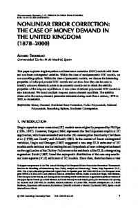
Design error correction procedures in combinational circuits described at the gate-level were proposed in [3-5]. However, the special structure of macro-based circuits and the special nature of the errors that can occur in them call for special error location tools. For example, the procedures of [3-5] rely on the fact that there is a small number of errors associated with every gate and every line in the circuit [2]. However, a Kmapping error even in a single macro can result in any one of 2(2 ) −1 functions, where K is the number of macro inputs. Even for small values of K, this number is too large to enumerate all the erroneous functions. An error location procedure specifically targeting macrobased circuits is proposed here. An error correction procedure for FPGAs was proposed in [6]. The method of [6] uses Boolean equations associated with lines in the circuit. The solutions give the correct functions of these lines. The solution is based on the use of BDDs. Consequently, the complexity of this method is higher than the method proposed here, which is based on simulation. In addition, only errors in the macro functions are considered in [6], and the errors are limited to clusters of macros at the same level of the FPGA, due to the complexity issue. The method proposed here is applicable to any distribution of errors. Fault location of gate-level circuits was considered in [7,8]. One of the most common diagnosis methods is based on a fault dictionary, where the response of modeled faults is stored and then compared to the response of the circuit-underdiagnosis. However, the large number of potential errors in macro-based circuits precludes the use of a dictionary. The error location procedure proposed in this work can be used instead. The paper is organized as follows. A review of relevant concepts and the definition of the error models considered in this work are given in Section 2. In Section 3 we describe the error location procedure for errors in the functions implemented by the macros. Three error multiplicities are considered, including errors affecting a single input combination of a single macro, errors affecting multiple input combinations of a single macro, and errors affecting multiple input combinations of multiple macros. In Section 4, we consider interconnection errors and describe an error location procedure for them. We also consider a combined procedure to locate both macro and interconnection errors. Section 5 presents experimental results for the two types of errors considered. Section 6 concludes the paper. 2. Preliminaries The following example demonstrates a macro-based circuit. Example : A macro-based circuit composed of three-input single-output macros is shown in Figure 1. The truth tables of the macros are shown in Table 1. Figure 1 together with the truth tables of Table 1 describe the macro-based circuit CM . ` A B C D
M3
M2
g3
E M4
g2
M1
g5
g6
Figure 1: An example of a macro-based circuit
Table 1: Truth tables for the macros of Figure 1 M1 M2 B E g2 c g6 A C g3 c g5 iiiiiiiiiiiiiiiiii iiiiiiiiiiiiiiiiii 0 0 0 0 1 1 1 1
0 0 1 1 0 0 1 1
0 1 0 1 0 1 0 1
c c c c c c c c c
0 0 0 1 0 1 0 1
0 0 0 0 1 1 1 1
M3 B C D c g3 iiiiiiiiiiiiiiiiii 0 0 0 0 1 1 1 1
0 0 1 1 0 0 1 1
0 1 0 1 0 1 0 1
c
c
c
c
c
c
c
c
c
1 1 1 1 0 0 0 1
0 0 1 1 0 0 1 1
0 1 0 1 0 1 0 1
c c c c c c c c c
1 0 1 0 1 0 1 1
M4
C D c g2 iiiiiiiiiiiii c 0 0 c 1 0 1 c 1 1 0 c 1 1 1 c 0
In this work, each macro is assumed to have a single output, however, the results can be extended to multi-output macros as well. The number of inputs to a macro is assumed to be small enough to allow a truth table to be written for it. Complete truth tables for macros are used throughout this work. Alternatively, BDDs or Boolean equations can be used to describe a macro. In our experiments, we consider Berkeley PLA benchmark circuits [9], synthesized into multi-level circuits and then mapped using the procedures of [10] into macro-based circuits. Two types of mappings are done in [10]. The mapping called bl uses the number of macros in the mapped circuit as a primary objective, thus attempting to reduce the area of the macro-based circuit. The mapping called fc uses testability as a primary objective. A complete description of these procedures can be found in [10]. For all macro-based circuits considered in this work, the number of macro inputs is limited to five. Information regarding the circuits we use is given in Table 2. After circuit name, we give the number of primary inputs, the number of primary outputs, the number of macros in the macro-based circuit for both types of mappings, and the number of primary input patterns used for error location. The first error model considered in this work consists of erroneous macro output values for one or more input combinations (minterms) of one or more macros. Such errors are referred to as macro errors. An example of a triple error in the circuit of Figure 1 is the following. The output of M 1 for input combination 011 is 0 instead of 1. The output of M 1 for input combination 100 is 1 instead of 0. The output of M 3 for input combination 001 is 0 instead of 1. Under the macro error model, we distinguish between three classes of errors, depending on their multiplicities. A single erroneous minterm of a single macro. Multiple erroneous minterms of a single macro. Multiple erroneous minterms of multiple macros. The second error model we consider consists of erroneous interconnections among macros. Such errors are referred to as interconnection errors. An example of a single interconnection error in the macro-based circuit of Figure 1 is the following. The third input of M 2 is connected to the output of M 4 (g 2 ), instead of the output of M 3 (g 3 ).
Table 2: Circuit parameters
c c macros c circuit c inp out c bl fc c patterns iiiiiiiiiiiiiiiiiiiiiiiiiiiiiiiiiiiiiii Z9sym cc 9 1 cc 83 128 cc 512 add6 12 7 c 23 45 c 4096 c adr4 5 c 10 13 c 256 c 8 alu1 8 c 8 8 c 4096 c 12 alu2 c 10 8 c 31 33 c 1024 c 10 alu3 8 c 32 36 c 1024 c 14 co14 1 c 12 30 c 10000 c 10 11 c 30 36 c 1024 dk17 c 8 c dk27 13 cc 256 c 15 179 c 13 dk48 37 43 c 10000 c c mish c 94 34 c 40 40 c 10000 radd 5 c 9 15 c 256 c 8 rckl c 32 7 c 48 64 c 10000 c 5 rd53 3 c 3 3 c 32 c 25 vg2 8 c 34 32 c 10000 c 27 c 10000 x1dn 6 c 28 c 27 c 36 32 c 10000 x9dn 7 31 cc 7 c c z4 4 c 7 10 c 128 Next, we demonstrate the effects of an error and the resolution that can be expected from the error location process. We use macro errors in these examples. First, we consider a design error, causing CM to produce erroneous primary output values. In this case, CIO is the error free specification of the circuit. Then, we consider error correction in the physical circuit, where CIO is the erroneous physical circuit and CM is the error free macrobased circuit. Example : Consider the macro-based circuit CM shown in Figure 1. Let CIO be a high level specification of CM . Suppose that in CM , macro M 3 produces an output 1 instead of an output 0 for input combination (BCD) = (110). In this case, the value of g 5 in CIO is different from its value in CM for primary input combinations (ABCDE) = (01100) and (01101). In CM , only M 3 and M 2 affect the value of g 5 , therefore, we concentrate on these macros. Under the given primary input combinations, (BCD) = (110) implies g 3 = 1 in CM (due to the error in CM , g 3 = 1 instead of 0), and (ACg 3 ) = (011) implies g 5 = 0. The error can be corrected by changing the output of M 3 in CM for input (BCD) = (110) from 1 to 0. No other change will correct the error. For example, we consider changing the value of g 5 for input combination (ACg 3 ) = (011). This does not fix the error in CM , since when input combination (ABCDE) = (00110) is applied, (BCD) = (011) implies g 3 = 1, and (ACg 3 ) = (011) will produce an erroneous value 1. Thus, CM remains erroneous after changing g 5 to 1 for (ACg 3 ) = (011). ` Example : Consider the macro-based circuit CM shown in Figure 1. Let CIO be the physical circuit corresponding to CM . Suppose that in CIO , macro M 3 produces an output 1 instead of an output 0 in response to the input combination (BCD) = (110). In this case, the value of g 5 in CIO is different from its value in CM for primary input combinations (ABCDE) = (01100) and (01101). In CM , only M 3 and M 2 affect the value of g 5 , therefore, we concentrate only on these macros. Under the given primary input combinations, (BCD) = (110) implies g 3 = 0 in (error free) CM , and (ACg 3 ) = (010) implies g 5 = 1. It is possible to make the output value of CM equal to the (erroneous) output value of CIO in one of the following ways. By changing the output of M 3 in CM for input (BCD) = (110) from 0 to 1, or by changing the output of M 2 in CM for input (ACg 3 ) = (010) from 1 to 0.
We can now translate these corrections into the following two errors in CIO . The output of M 3 in CIO for input (BCD) = (110) is 1 instead of 0, or the output of M 2 in CIO for input (ACg 3 ) = (010) is 0 instead of 1. ` Note that the difference between the two examples is that in the first one, CM is erroneous and CIO is error free, whereas in the second one, CM is error free and CIO is erroneous. From here on, the examples will be given for an error free CM and an erroneous CIO . From the previous example it can be seen that if two different errors result in the same input/output behavior, then the location procedure cannot be expected to identify the actual error made. The location procedure can be used to find the first error, or all the errors that can explain the circuit behavior. In some cases, where certain errors are easier to correct than others, obtaining more than one candidate error may facilitate the correction process. In the following sections, we present the location procedures. We use the following terminology. We say that the output of Mi in CM is sensitized by a primary input pattern α if changing the output value of Mi in CM under α changes the value of at least one primary output (CM can be error free or erroneous, depending on the context). We also define sensitization of a macro input in CM . We say that input j of Mi in CM is sensitized by a primary input pattern α if changing the value of input j under α changes the value of at least one primary output of CM . Here, if input j is a fanout branch of a stem driving more than one macro, only the value of the branch driving Mi is changed in order to check whether the input is sensitized. The error location procedures proposed in this work are based on simulation of primary input patterns applied to CIO and CM , and comparison of the primary output responses of the two circuits. The input patterns used can be random, or can be a result of a test generation procedure for error detection or for error location. The set of input patterns should be large enough to allow accurate error location. Ideally, all input patterns where erroneous output values are obtained should be known. However, correction can also be based on a limited subset of input patterns. The set of input patterns used is denoted by T. All the examples in this paper are based on the macrobased circuit shown in Figure 1 under an exhaustive set of input patterns T that includes all 32 input patterns. In addition, we assume the context where CM is error free and CIO is an erroneous physical circuit.
3. The error location process for macro errors In this section, we present the error location procedure for macro errors. We say that an erroneous primary output value is observed in response to a primary input combination α, when the output produced by CIO in response to α is different from the output produced by CM in response to α (depending on the context, the erroneous output value may be that of CIO or that of CM ). We say that error free primary output values are observed in response to a primary input combination α, if the output values produced by CIO and the output values produced by CM in response to α are the same.
3.1 Preprocessing The first step of the location procedure for macro errors is to collect information relating the erroneous values observed on the primary outputs with the sensitization of macro output values in CM . For every macro Mi and every macro input combination β, the following counts are kept for this purpose. nes (Mi ,β) is the number of primary input combinations for which an erroneous output is observed (marked by e), and in CM , β is applied to Mi and the output of Mi is sensitized (s). nesh(Mi ,β) is the number of primary input combinations for which an erroneous output is observed (e), and in CM , β is applied h to Mi and its output is not sensitized (s). nehs (Mi ,β) is the number of primary input combinations for which h an error free output is observed (e), and in CM , β is applied to Mi and its output is sensitized (s). nehsh(Mi ,β) is the number of primary input combinations for which h an error free output is observed (e), and in CM , β is applied h to Mi and its output is not sensitized (s). The following procedure is used to update the counts for a given set of primary input patterns T. Procedure 1: Relating erroneous output values and sensitization of macro outputs (1) For every input combination β of every Mi , set nes (Mi ,β) = 0, nesh(Mi ,β) = 0, nehs (Mi ,β) = 0, and nehsh(Mi ,β) = 0. Set Nerr = 0 (Nerr is used to record the number of primary input combinations in T, for which erroneous output values are obtained). (2) For every primary input combination α ∈ T: (a) Apply α to CIO and CM . Compute the output values of CIO and CM . If the primary output values are equal in both circuits, set ERR = 0. Else set ERR = 1 and increment Nerr by one. (b) For every Mi in CM : Check if the output of Mi is sensitized in CM . Set SENS = 1 if the macro output is sensitized, and set SENS = 0 otherwise. Let β be the input combination of Mi when α is applied to CM . If ERR = 1: If SENS = 1, increment nes (Mi ,β) by one. If SENS = 0, increment nesh(Mi ,β) by one. If ERR = 0: If SENS = 1, increment nehs (Mi ,β) by one. If SENS = 0, increment nehsh(Mi ,β) by one. In the following sections, we use the counts computed by Procedure 1 to identify errors of different multiplicities.
3.2 Single macro, single input combination Suppose that a single macro is erroneous. Let it be Mi . Suppose in addition that the error affects a single input combination β of Mi . Then the only time an erroneous primary output value can be observed is if a primary input combination α is applied, that results in β on the inputs of Mi . At the same time, α must sensitize the output of Mi in CM (note that if CM is the erroneous circuit, then β produces an erroneous output value of Mi in CM , and if CIO is the erroneous circuit, then β produces an erroneous output value of Mi in CIO . In both cases, we are interested in the sensitization of Mi in CM as the cause for the different output values observed). In other words, all Nerr erroneous primary output combinations observed are due to β being applied to Mi
when the output of Mi is sensitized in CM . Using the counts computed by Procedure 1, we have nes (Mi ,β) = Nerr . In addition, if the output of Mi is not sensitized in CM when β is applied to Mi , then error free output values must be observed. Therefore, nesh(Mi ,β) = 0. Also, if β is applied to Mi and the output of Mi is sensitized, then an erroneous primary output value must be observed. Therefore, nehs (Mi ,β) = 0. We thus have, for an input combination β of Mi that produces an erroneous value, nes (Mi ,β) = Nerr , nesh(Mi ,β) = 0, and nehs (Mi ,β) = 0 These equations can be used to identify an error involving a single macro and a single macro input combination. Note that macro input combinations that are never obtained under the given set of primary input combinations, or where the output is never sensitized, have all-zero counts. Thus, if the macro output is erroneous for such an input combination, it will not be corrected. The correction process can be completed in this case by generating additional input combinations, that assign the remaining macro input combinations, while sensitizing the macro output.
3.3 Single macro, multiple input combinations Suppose now that a single macro, Mi , is erroneous, and that the error affects multiple input combinations of Mi . Let the set of input combinations affected be B. Then the only time an erroneous output can be observed is if a primary input combination α is applied, that results in an input combination β ∈ B on the inputs of Mi . At the same time, α must sensitize the output of Mi in CM . In other words, all Nerr erroneous primary output combinations observed are due to one of the combinations in B being applied to Mi when the output of Mi is sensitized in CM . Using the counts computed by Procedure 1, we have Σ nes (Mi ,β) = Nerr ,
Σ nesh(Mi ,β) = 0, and βΣ∈ Bnehs (Mi ,β) = 0 β∈B
β∈B
The search for the subset B is facilitated by the following property. Lemma 1: For an error that affects a single macro, Mi , let B = {β} be the set of input combinations of Mi for which nesh(Mi ,β) = 0, nehs (Mi ,β) = 0 and nes (Mi ,β) > 0. Then Σ nes (Mi ,β) = Nerr . β∈B
Proof: Let B = {β} be the set of input combinations of Mi for which nesh(Mi ,β) = 0, nehs (Mi ,β) = 0 and nes (Mi ,β) > 0. Let B′ = {β′} be the set of input combinations of Mi for which nesh(Mi ,β′) = 0 and nehs (Mi ,β′) = 0. First, we show that B′ contains every input combination of Mi that produces an erroneous macro output value. To show this, we show that input combinations γ such that nesh(Mi ,γ) > 0 or nehs (Mi ,γ) > 0, which are excluded from B′, do not produce erroneous output values. Consider an input combination γ of Mi such that nesh(Mi ,γ) > 0. This implies that when γ is applied to Mi , an error is observed on the primary outputs even though the output of Mi is not sensitized. Thus, Mi cannot be the cause of the error and another macro, M j , must contain an error. This contradicts our assumption that all the errors are associated with Mi . Next, consider an input combination γ of Mi such that nehs (Mi ,γ) > 0. Then no error is observed on the primary outputs, although γ is applied to Mi and the output of Mi is sensitized. This implies that the output value of Mi for γ is error free. Hence, γ is correctly excluded from B′. The set B contains every combination contained in B′, except for the input combinations for which nesh(Mi ,β) = 0, nehs (Mi ,β) = 0 and nes (Mi ,β) = 0. If nes (Mi ,β) = 0, then either β is never
obtained when the output of Mi is sensitized, or the output value for β is error free. In either case, β does not contribute to erroneous primary output values. Consequently, B contains every input of Mi that causes an erroneous output value of Mi during T. If Σ nes (Mi ,β) < Nerr , then all the input combinations of Mi that β∈B
produce erroneous macro output values are not sufficient to produce all the erroneous primary output values observed. This is a contradiction to the fact that errors are present only in Mi . Consequently, Σ nes (Mi ,β) ≥ Nerr . β∈B
Consider a macro input combination β for which nesh(Mi ,β) = 0, nehs (Mi ,β) = 0 and nes (Mi ,β) > 0. Let α be a primary input combination that contributes to nes (Mi ,β). Since β creates an erroneous macro output value and the macro output is sensitized in CM , an erroneous output value must be produced. Thus, α contributes to Nerr . Consequently, Σ nes (Mi ,β) ≤ Nerr . β∈B
From the two inequalities above,
Σ nes (Mi ,β) = Nerr . `
β∈B
Based on Lemma 1, for every Mi , we need to add up the counts nes (Mi ,β) > 0 such that nesh(Mi ,β) = 0 and nehs (Mi ,β) = 0. If the sum is equal to Nerr , the macro can explain the erroneous output values observed. Note that we exclude macro input combinations such that nesh(Mi ,β) = 0 nehs (Mi ,β) = 0 and nes (Mi ,β) = 0 since such combinations do not affect the correctness of the primary output values. We prefer to exclude them in order to minimize the error multiplicity. As in the case of single errors in single macros, erroneous primary output values may be explained by more than one error.
3.4 Multiple macros, multiple input combinations Suppose that macros {M 1 ,M 2 , . . . ,Mk } are erroneous. Let the error affect one or more input combinations of Mi , 1 ≤ i ≤ k. Let the set of input combinations affected in Mi be Bi . Due to the existence of multiple erroneous macros, error masking can occur. An example can be found in [11]. Due to masking, nehs (Mi ,β) > 0 can be obtained even if input combination β of Mi produces an erroneous output. Therefore, contrary to the case of a single erroneous macro, the condition nehs (Mi ,β) = 0 cannot be imposed when identifying a multiple macro, multiple input combination error. However, anticipating that error masking is rare, we propose the following procedure for multiple error location. The procedure identifies the multiple error in steps. At every step, a macro Mi and an input combination β of Mi are selected, for which nehs (Mi ,β)+nesh(Mi ,β) is minimum and nes (Mi ,β) is maximum. The pair (Mi ,β) is recorded as an error component. The output value of Mi in CM for input combination β is then complemented, the values of the various counts are recomputed, and the next pair is selected. The process terminates when one of the following conditions is satisfied. (1) The number of primary input patterns causing erroneous primary output values, Nerr , is zero. In this case, the error consists of the recorded pairs. (2) A predetermined number of pairs has been selected, and CIO and CM still have different primary output values for the same primary input combination. In this case, the procedure terminates without identifying the error. The following case requires special attention. In some cases, the error location procedure may select an input combination β of Mi more than once. After selecting it an even number of times, the original output value is restored. To prevent the procedure from going in a loop where β is repeatedly selected, we
restrict the number of times a given input combination of a given macro can be selected to two. If an input combination is selected twice, it is not considered as a component of the error. The location procedure is given next. Procedure 2: Location of multiple macro, multiple input combination errors (1) Set L = φ and Nmod = 0. For every Mi and every input combination β of Mi , set changed (Mi ,β) = 0. (2) Execute Procedure 1. (3) If Nerr = 0, stop: the error is located and its components are stored in L. (4) Select input combination β of Mi , such that changed (Mi ,β) < 2, and nehs (Mi ,β)+nesh(Mi ,β) is minimum. In case of ties, select β and Mi for which nes (Mi ,β) is maximum. If no such input combination exists, stop: correction cannot be completed. (5) If changed (Mi ,β) = 0, set L = L ∪{(Mi ,β)}. Else, set L = L−{(Mi ,β)}. Complement the output value of Mi under input combination β. Set changed (Mi ,β) = changed (Mi ,β)+1 (6) Set Nmod = Nmod +1. If Nmod does not exceed a predetermined limit on the number of modifications allowed to CM , go to Step 2. Note that Procedure 1 is executed every time a macro output value is changed in CM , to account for the fact that the number of erroneous output values may change, as well as the counts. In Section 5, we present experimental results of the location procedure. Procedure 2 does not guarantee the location of an error. To guarantee error location, a search procedure such as branch-and-bound should be used, that is capable of exploring more than one way of changing CM , until CM and CIO become equivalent. The heuristics used in Procedure 2 can be used to guide the branch-and-bound process. We did not pursue this possibility in this work, and used only Procedure 2 for multiple error location of multiple macros. In most cases, Procedure 2 was sufficient to correctly locate multiple errors.
3.5 Summary and extensions Based on the discussion of the previous subsections, the following procedure is proposed for error location of any error multiplicity. After obtaining the counts using Procedure 1, the error location procedure checks whether the error is (or behaves like) a single macro, single input combination error. If not, it checks whether the error is (or behaves like) a single macro, multiple input combination error. Only if the error cannot be identified as a single macro error, Procedure 2 is applied to identify a multiple macro, multiple input combination error. In the previous subsections, we did not consider the fact that certain macros can only affect certain primary outputs. For example, in the circuit of Figure 1, M 1 and M 4 can only affect g 6 and M 2 and M 3 can only affect g 5 . Thus, if only g 6 is erroneous and M 2 is sensitized with input combination β, then the output response of M 2 to β must be error free (unless error masking occurred). To accommodate this additional information, it is possible to compute the counts nes , nesh, nehs and nehsh for every primary output separately. The extended counts are nes (Mi ,β,O j ), nesh(Mi ,β,O j ), nehs (Mi ,β,O j ), and nehsh(Mi ,β,O j ), where O j is a primary output. For illustration, we consider next the single macro,
single input combination case under this extension. Suppose that an error affects a single input combination β of a macro Mi . Then the only time an erroneous value can be obtained on output O j is if a primary input combination α is applied, that results in β on the inputs of Mi . At the same time, α must sensitize the output of Mi and propagate it to O j . In other words, nes (Mi ,β,O j ) = Nerr (O j ), nesh(Mi ,β,O j ) = 0, and nehs (Mi ,β,O j ) = 0. Here, Nerr (O j ) is the number of primary input patterns for which an erroneous value is observed on O j . We did not implement this extension.
4. Location of interconnection errors In this section, we consider the location of interconnection errors. An interconnection error is an error where an input of a macro, that should be driven from macro or primary input j in an error free circuit, is driven from a different macro or primary input in the erroneous circuit. An interconnection error can be used to model an error where an input of a macro is missing, assuming that the missing input is constantly 0 or 1. Adding a dummy line that is fixed at 0 or 1 allows the error to be located. In addition, multiple interconnection errors can be used to model errors that interchange lines in the circuit.
4.1 Preprocessing Similar to the error location procedure for macro errors, we define four counts to be used for error location. In the case of macro errors, counts were associated with input combinations of macros. In the case of interconnection errors, the counts are associated with macro inputs. Using the definition of input sensitization given in Section 2, we define the following counts for every input j of Mi . As before, the counts are defined for a given set of primary input patterns T. nes (Mi , j) is the number of primary input combinations in T for which an erroneous primary output value is observed (e), and input j of Mi is sensitized in CM (s). nesh(Mi , j) is the number of primary input combinations in T for which an erroneous primary output value is observed (e), and h input j of Mi is not sensitized in CM (s). h nes (Mi , j) is the number of primary input combinations in T for h which error free primary output values are observed (e), and input j of Mi is sensitized in CM (s). nehsh(Mi , j) is the number of primary input combinations in T for h which error free primary output values are observed (e), and h input j of Mi is not sensitized in CM (s). The procedure for computing the counts above is similar to Procedure 1, except that β is replaced by input j. We refer to the procedure for computing the counts for interconnection error location as Procedure 3. We do not repeat it here, due to its similarity to Procedure 1. In the following sections, we use the counts computed by Procedure 3 to locate interconnection errors of various multiplicities. We also consider the relationship to the macro error location procedure. We point out that the location procedures proposed for interconnection errors only identify which macro inputs are erroneously connected. They do not identify the correct connection. This is different from the location of macro errors, where an error associated with input combination β of Mi can be corrected by complementing the output value of Mi when β is applied to it. Identifying the correct connection in the case of interconnection errors requires consideration of every possible alternative connection to every error site. Due to space considerations, we do not consider this method in
detail here, however, we point out that it is similar to the solution used in gate-level circuits [3,4]. In addition, we do not consider interconnection errors that create feedback.
4.2 Single interconnection errors In case of a single interconnection error affecting input j of Mi , an erroneous output value can be observed only when input j is sensitized. Thus, we have in this case nes (Mi , j) = Nerr . In addition, nesh(Mi , j) = 0, since an erroneous primary output value cannot be observed unless input j of Mi is sensitized. However, if input j of Mi is sensitized, an erroneous primary output value may or may not be obtained. This depends on whether the macro or primary input to which input j is erroneously connected produce the error free value of input j or not. Thus, we have no requirement on nehs (Mi , j). In addition, no requirements exist for nehsh(Mi , j). The following example demonstrates the use of the counts for error location. Example : Consider the interconnection error where, in the physical circuit, input g 3 of M 2 in Figure 1 is connected to the output of M 4 , instead of the output of M 3 . The number of primary input combinations with an erroneous output value is 14. The counts for all inputs of all macros are shown in Table 3. The only input with nes (Mi , j) = 14 and nesh(Mi , j) = 0 is input g 3 of M 1 , thus identifying the error location. ` Table 3: Count values c inp c nes nesh nehs nehsh imacro iiiiiiiiiiiiiiiiiiiiiiiiiiiiiiiiii c B c 5 9 7 11 M1 c E c 0 14 12 6 c g 2 c 13 1 11 7 i iiiiiiiiiiiiiiiiiiiiiiiiiiiiiiiiii c A c 4 10 8 10 M2 c C c 0 14 10 8 c g 3 c 14 0 10 8 i iiiiiiiiiiiiiiiiiiiiiiiiiiiiiiiiii c B c 10 4 10 8 M3 c C c 6 8 0 18 c D c 4 10 0 18 i iiiiiiiiiiiiiiiiiiiiiiiiiiiiiiiiii c C c 7 7 5 13 M4 c D c 5 9 7 11
4.3 Multiple interconnection errors In case of multiple interconnection errors involving a subset of inputs J = {j} of the same macro, Mi , an erroneous output value is observed in response to a primary input combination α whenever an input j ∈ J satisfies the following conditions under α. (1) Input j carries an erroneous value, and (2) input j is sensitized. In the macro error case, α resulted in a given macro input combination β whose count nes was then incremented. However, in the case of interconnection errors, counts of several inputs of Mi may be incremented due to the same primary input combination α. Thus, for an interconnection error involving J we have Σ nes (Mi , j) ≥ Nerr . No condition can be given for nesh(Mi , j), j ∈J
since other inputs may result in an erroneous primary output value even if input j ∈ J is not sensitized. Similarly, no condition can be given for nehs (Mi , j), since even when input j is sensitized by a primary input combination α, it may assume its error free value under α. Since the condition Σ nes (Mi , j) ≥ Nerr may j ∈J
be satisfied by a large number of macros, we add the following counts, that help to reduce the number of macros that can potentially explain the erroneous output response. For every candidate subset J such that Σ nes (Mi , j) ≥ Nerr we compute the folj ∈J
lowing counts.
nes (Mi ,J) is the number of primary input combinations in T for which an erroneous primary output value is observed (e), and at least one input j ∈ J of Mi is sensitized (s). nesh(Mi ,J) is the number of primary input combinations in T for which erroneous primary output values are observed (e), and h no input j ∈ J of Mi is sensitized (s). A subset J of inputs of Mi having interconnection errors must satisfy nes (Mi ,J) = Nerr and nesh(Mi ,J) = 0. In case of multiple interconnection errors involving inputs of more than one macro, it is possible to use an approach similar to the one we used for multiple macro errors. However, before such an approach can be considered, a method is required to correct each error component as it is found. Due to space considerations, we do not pursue this problem here.
4.4 Mixed errors Since macro errors and interconnection errors are located using different counts, they can be considered simultaneously as follows. First, Procedures 1 and 3 are used to compute the counts. Then, identification of errors involving single macros is attempted, using the rules derived in Subsections 3.2, 3.3, 4.2 and 4.3. If it turns out that the error involves multiple macros, then a procedure similar to Procedure 2 is used, where a single error component (either macro error or interconnection error) is selected at every step according to the following criteria. For macro error E involving macro Mi and input combination β, set C 1 (E) = nehs (Mi ,β)+nesh(Mi ,β) and C 2 (E) = nes (Mi ,β). For interconnection error E involving macro Mi and input j, set C 1 (E) = nesh(Mi , j) and C 2 (E) = nes (Mi , j). Select the error E for which C 1 is minimum and, in case of ties, C 2 is maximum. The error selected is fixed in CM , and the process continues with the modified circuit CM .
mark it and set Nerrors = Nerrors +1. Complement the output values for the marked input combinations to obtain the error. All multiple errors injected in our experiments had multiplicity five. Next, we describe the results of error correction for the various error types. For single macro, single input combination errors, the correction procedure given in Section 3.1 is complete, i.e., the procedure is guaranteed to find a modification to CM that will make it equivalent to CIO . The purpose of implementing the procedure and presenting its results is to check the number of different ways in which an error can be corrected (recall that it may be possible to correct a given error in several ways). For this purpose, we look for all macro input combinations that satisfy the equalities nes (Mi ,β) = Nerr , nesh(Mi ,β) = 0, and nehs (Mi ,β) = 0. For different injected errors, the number of macro input combinations satisfying these equations may be different. In Table 4, we report the average number of macro input combinations that satisfy these equations, in two contexts. In the first two columns, the errors are injected into a physical circuit CIO and CM is an error free circuit. In the next two columns, the errors are injected into CM , and CIO is an error free specification of CM . Due to the similarity between the two sets of results, we report only results for physical circuit errors in the rest of this section. Table 4: Single macro, single input combination errors (3)
c
5. Experimental results In this section, we present experimental results of error location in the macro-based circuits of Table 2. For circuits with up to 13 inputs, the set of input patterns T is the exhaustive set of all input combinations. For larger circuits, the first 10,000 patterns in an exhaustive set of input patterns was used. In each case, we injected 100 randomly selected errors. To inject a single macro, single input combination error, we randomly select a value for i and β, and inject an error in input combination β of Mi . In case of single macro, multiple input combination errors, we perform the following procedure to inject an error of multiplicity M. (1) Set Nerrors = 0. Select i randomly. Unmark all input combinations of Mi . (2) Repeat until Nerrors = M: Select a random value for β. If input combination β of Mi is not marked, mark it and set Nerrors = Nerrors +1. (3) Complement the output values for the marked input combinations to obtain the error. To inject a multiple macro, multiple input combination error of multiplicity M, we performed the following procedure. (1) Set Nerrors = 0. Unmark all input combinations of all macros. (2) Repeat until Nerrors = M: Select a random value for i and a random value for β. If input combination β of Mi is not marked,
av.errors
c physical circuit c design errors c bl circuit c fc fc iiiiiiiiiiiiiiiiiiiiiiiiiiiiiiiiiiiiiiiiiii c bl Z9sym c 232.30 43.02 c 205.34 42.98 add6 3.83 cc 17.86 3.44 c 14.46 adr4 3.19 1.45 3.83 1.65 c c alu1 c 1.00 1.00 c 1.00 1.00 c 17.30 alu2 8.58 c 17.35 9.92 c 12.16 alu3 6.97 c 13.23 3.67 c 17.25 co14 4.71 c 20.61 4.37 c 13.14 c dk17 1.61 11.37 1.52 c 2.15 dk27 1.16 c 2.04 1.16 c 19.21 dk48 4.66 cc 14.68 4.33 c mish c 365.89 365.89 c 361.33 361.33 radd c 2.05 1.50 1.90 1.73 c 462.85 397.39 cc 462.77 384.70 rckl c 3.00 rd53 3.00 c 3.00 3.00 c 438.94 294.44 c vg2 389.56 306.07 c 282.23 300.24 c 300.87 316.32 x1dn c 332.34 281.30 c 337.15 260.30 x9dn cc 3.88 z4 2.13 cc 3.86 2.01 Similar to single macro, single input combination errors, the procedure for single macro, multiple input combination errors is also guaranteed to correctly identify an error. Our interest is, therefore, in the number of different ways an error can be corrected, i.e., in the number of subsets B that satisfy Σ nes (Mi ,β) = Nerr , Σ nesh(Mi ,β) = 0, and Σ nehs (Mi ,β) = 0. β∈B
β∈B
β∈B
The average number of subsets B found for the different errors injected are given in Table 5. In the case of multiple macro, multiple input combination errors, we are interested in the number of multiple errors that can be correctly identified by the greedy location procedure proposed. We therefore searched for the first multiple error that can be used to correct the injected error (and not for all errors, as in Tables 4 and 5 above). The results for multiple macro, multiple input combination errors are given in Table 6. After circuit name, we give the number of multiple errors diagnosed
Table 5: Single macro, multiple input combination errors
c av. errors circuit c fc iiiiiiiiiiiiiiiiiiiiiiii c bl Z9sym cc 3.71 1.47 add6 1.75 2.18 c adr4 c 2.02 2.46 alu1 c 1.00 1.00 alu2 c 1.17 1.16 c 1.14 1.36 alu3 c 1.32 1.49 co14 c 1.03 2.53 dk17 cc 2.41 1.47 dk27
c av. errors circuit c bl fc iiiiiiiiiiiiiiiiiiiiiiii c c 2.00 dk48 2.98 c 30.24 30.24 mish c radd 2.50 c 2.42 rckl c 22.08 26.90 rd53 c 3.00 3.00 c 21.03 19.69 vg2 c 16.97 18.88 x1dn c 16.50 16.37 x9dn cc 1.94 z4 2.15
correctly, i.e., errors such that an error free circuit is obtained if the errors identified by Procedure 2 are corrected. The average multiplicity of the identified errors, over all correctly diagnosed errors, is given next. The multiplicity is the number of components found by Procedure 2 for a given error. This information is given for both types of mappings considered. It can be seen that in some cases, the greedy approach may not be sufficient to correctly locate an error. Extensions of Procedure 2 that use branch-and-bound to improve the results are currently being considered. Table 6: Multiple macro, multiple input combination errors c c bl fc
c av. c av. c corr multip c corr multip icircuit iiiiiiiiiiiiiiiiiiiiiiiiiiiiiiiiiii c 61 c 40 Z9sym c 3.26 c 4.05 add6 72 4.38 4.40 c c 52 adr4 4.72 c 94 4.74 c 85 alu1 c 100 5.00 c 100 5.00 c 62 alu2 4.18 c 67 4.54 c 64 alu3 4.31 c 61 4.61 c 53 co14 3.72 c 70 4.34 c 54 dk17 4.33 cc 70 4.76 c dk27 4.80 c 90 5.00 c 87 dk48 4.21 c 62 4.63 c 57 mish 0.80 c 91 0.80 c 91 radd c 93 4.80 c 80 4.71 c 93 rckl 1.80 c 92 2.15 c 81 rd53 5.00 c 81 5.00 c 92 vg2 0.53 c 98 0.96 c 94 x1dn 0.94 cc 95 0.98 c x9dn 77 1.51 c 89 1.58 c z4 c 95 4.64 c 96 4.72
The results for single interconnection errors are given in Table 7. As in the case of single macro errors, complete correction is guaranteed in this case, and we are interested only in the number of different modifications that can fix a given error. Table 7: Single connection errors
c av. errors c bl fc iiiiiiiiiiiiiiiiiiiiiiii c Z9sym cc 15.13 11.72 add6 14.21 14.24 c adr4 c 11.22 11.19 alu1 c 1.11 1.11 alu2 c 9.86 14.75 c 12.99 15.29 alu3 c 7.53 14.07 co14 c 12.03 11.46 dk17 cc 4.77 5.65 dk27 circuit
c av. errors c bl fc iiiiiiiiiiiiiiiiiiiiiiii c c 20.81 22.69 dk48 c 94.40 94.40 mish c 11.01 11.06 radd c rckl c 85.10 115.65 rd53 c 5.48 5.48 c 104.76 95.79 vg2 c 74.84 80.10 x1dn c 76.73 70.62 x9dn cc 9.63 z4 9.86 circuit
6. Concluding remarks We considered the problem of correcting errors in a macro-based circuit. The problem formulation allowed the correction of errors that arise both in the context of design error correction, before the circuit is realized, and in the context where a physical circuit needs to be corrected. Error correction was done based on simulation of input patterns and comparison of an observed response from the circuit-under-correction to an expected response. Generation of input patterns to facilitate correction is currently under investigation. Two error classes were defined, namely, macro errors and interconnection errors. Both single and multiple errors of each type were considered. Accurate correction procedures were given for single errors. Heuristics were given for correcting multiple errors. Experimental results were given to demonstrate the various correction procedures.
References [1]
[2]
[3]
[4]
[5] [6]
[7] [8]
[9]
[10] [11]
K. Keutzer, "DAGON: Technology binding and local optimization by DAG Matching", in Proc. 24th Design Autom. Conf., 1987, pp. 341-347. M. S. Abadir, J. Ferguson and T. E. Kirkland, "Logic Design Verification via Test Generation", IEEE Trans. on Computers, Jan. 1988, pp. 138-148. S.-Y. Kuo, "Locating Logic Design Errors via Test Generation and Don’t-Care Propagation", 1992 Europ. Design-Autom. Conf., Sept. 1992, pp. 466-471. P.-Y. Chung and I. N. Hajj, "ACCORD: Automatic Catching and Correction of Logic Design Errors in Combinational Circuits", 1992 Intl. Test Conf., pp. 742-751, 1992. I. Pomeranz and S. M. Reddy, "On Correction of Multiple Design Errors", 3rd Intl. Conf. on VLSI and CAD, 1993. Y. Kukimoto and M. Fujita, "Rectification Method for LookupTable Type FPGA’s", in Proc. 1992 Intl. Conf. on ComputerAided Design, Nov. 1992, pp. 54-61. E. J. McCluskey, "Test and Diagnosis Procedure for Digital Networks", Computer, Jan. 1971, pp. 17-20. R. E. Tulloss, "Fault Dictionary Compression: Recognizing when a Fault May Be Unambiguously Represented by a Single Failure Detection", 1980 Test Conf., Nov. 1980, pp. 368-370. R. Brayton, G. D. Hachtel, C. McMullen, and A. L. Sangiovanni-Vincentelli, Logic Minimization Algorithms for VLSI Synthesis, Kluwer Academic Publishers, 1984. I. Pomeranz and S. M. Reddy, "Testability Considerations in Technology Mapping", 3rd Asia Test Symp., Nov. 1994. I. Pomeranz and S. M. Reddy, "On Error Correction in MacroBased Circuits", Technical Report No. 4-1-1994, ECE Dept., U. of Iowa.