On Schema and Functional Architectures for Multilevel Secure and Multiuser Model Federated DB Systems Elena Rodrígueza
[email protected] a
Marta Olivab
[email protected]
Fèlix Saltora
[email protected]
Benet Campderrichc
[email protected]
Dept. de Llenguatges i Sistemes Informàtics, Universitat Politècnica de Catalunya, E-08028 Barcelona. b Dept. d’Informàtica i Enginyeria Industrial, Universitat de Lleida, E-25003 Lleida. c Dept. d’Enginyeria Informàtica, Universitat Rovira i Virgili, E-43006 Tarragona. Abstract This paper presents an approach for thigtly federated database systems with several federated schemas that consist of a schema architecture and a functional architecture. The reference schema architecture has been extended to deal with security aspects not well solved previously. The functional architecture includes the processors needed to build the federation and the main modules of the execution architecture.
1 Introduction The growing need of cooperation among independent entities implies accesses to several heterogeneous, autonomous and distributed database systems. This cooperation requires interconnecting the database systems by a communication network, and overlapping a software layer upon the database management systems (DBMSs) to support their interoperation, sharing their data but preserving their autonomy. We assume that the technical form of cooperation is interoperability1, supporting integrated access to the collection of databases. This means that a user is able to ask a single query and receives a single, consolidated answer as if he2 was working against a single database. We assume the reader is familiar with the concepts and problems involved in such systems, as explained in [SL90] and [BE96]. We are interested in tightly federated database systems (FDBSs) with several Federated Schemas, that is, a degree of autonomy intermediate between loosely coupled and full tightly coupled FDBS. For us, full tightly coupled FDBS means that we have only one federated schema and interdependencies. To support integrated access, the FDBS must have an adequate architecture which depends on the building and operation requirements of the federation. Different schema architectures for FDBSs have been proposed, particularly the 5-level reference architecture by Sheth and Larson where they discuss issues related to the building phase of a FDBS and only outline some aspects related to the operation phase. Although this reference architecture is quite general and separates the issues into different schema levels and specific processors, we believe there are situations where it has shortcomings. In [SCRR96] we showed three particular issues that do not fill well within the 5-level architecture by Sheth and Larson: component databases of several federations, external schemas in user models different from the canonical model and multiple semantics at the federated schema level. In this paper we deal with problems related to User Schemas expressed in user models that differ from the canonical data model (CDM) and access control and security issues. In addition we sketch an architecture for a FDBS that satisfies the following characteristics: • Supports both federated and preexisting users. • The component databases (CDBs) could be relational and object-oriented database systems.
1
2
We use italics for a word or expression for emphasis when it appears for the first time or for reserved words in our canonical data model. We use he for “he or she”, his for “his or her”.
• The security model of all CDBs is based in a mandatory access control (MAC), in particular is a multilevel security model. Multilevel security models of CDBs could be heterogeneous. For further information see [DJ94], [P94]. • From a security point of view, CDBs can have two types of autonomy (only security control at federated level or security control at federated and component levels). • Each Federated Schema supports solely one semantics. • The federated users could work with FDBS using the canonical data model (CDM) of the federation or using their own native data models. • The CDM is object-oriented, in our case is BLOOM ([CSG94]). • At this stage our FDBS considers read-only queries. Our architecture distinguishes between the schema architecture and the functional architecture of the FDBS. The schema architecture includes a set of schemas organized in different levels in order to solve syntactic and semantic heterogeneities and distribution problems. On the other hand, the functional architecture is formed by several processors needed both in the construction and operation phases. To explain our architecture we will focus in the process of building a federation from several CDBs and the involved steps in the execution of a federated read-only query. shipment [P]
waste [P]
customers [P]
sh_code 0111
waste_code 060105
prod_code 123
waste_code 060105
waste_name Nitric Acid
risk [C] 3
060105
Acid
-
060105
Liquid
-
customer_code 123 321
customer_type P R
rec_code 321
TC P
precautions [R ] TC Explosive; C Keep cool Explosive; R Keep cool P
company_name C.I.Q.S.A. T.R.I.S.A.
address Pi, 5, Reus Major, 2, Vich
TC P P
CDB1 shipments [L]
wa_codes
...
wa_name
sh_code e od _c wa
rec_ code
ver recei
sh_codes
strings
integers
strings
classes 0111
component
3
strings
neutralize with a base
[H]
risk: integers [H] precaution: strings [H] producer: producers receiver: receivers sh_code: sh_codes ... id sh_code oc: {L, H} end_class
class producers [L] simple_aggreg_of company_name: strings pr_code: pr_codes ... id pr_code oc: {L, H} end_class class receivers [L] simple_aggreg_of company_name: strings treatment_type: tr_codes rec_code: rec_codes ...
[L] 123
role
co mp an y_ na me
...
Liquid
objects
060101
Sulphuric Acid
simple_aggreg_of wa_code: wa_codes wa_name: strings
strings
...
producers [L]
pr_codes
060101
class shipments [L]
rec_codes
producer prec auti ris on [H k[ ] H]
de co pr_
0111
tr_codes type ent_ treatm compan y_name
receivers [L]
C.I.Q.S.A. [L]
321
T.R.I.S.A.
V1 [L]
simple aggregation
id rec_code oc: {L, H} end_class
CDB2
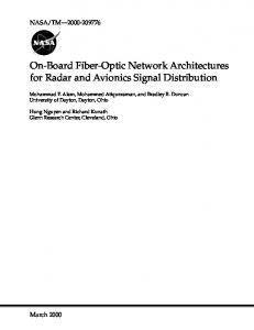
Figure 1. Component Databases of the Running Example. Along this paper we will illustrate our schema and functional architectures through an example (see figure 1) that includes two CDBs. Each CDB belongs to an enterprise that transports industrial wastes from the industry that produces them (from now called producer1) to the industry/organization responsible for their final treatment (called receiver). Figure 1 shows the conceptual schemas and some data items of CDB1 (a relational database located at site 1) and CDB2 (an object-oriented database placed at site 2). Both CDBs follow a multilevel security model: CDB1 contemplates three levels of data classification (Confidential (C), Restricted (R) and Public (P)) whereas CDB2 classifies data in two 1
In the text, we use the courier font for attributes, classes or relation names of the running example
levels (High (H) and Low (L)). For instance, in CDB1, if a user queries the information available about the waste with waste_code 060105 the data items that he would obtain (depending on his clearance) would be [Nitric Acid, 3, Explosive; Keep cool], [Acid, Explosive; Keep cool] or [Liquid]. Also note that both CDB1 and CDB2 have a shipment with sh_code 0111. In spite of this, they denote different real world objects and after the federation had been built they must be distinguished as different. This paper is organized as follows: section 2 presents our 7-level schema architecture and the processors needed to obtain it during the construction phase. In section 3 we explain the functional architecture, that includes different modules, involved in the execution phase of a FDBS. Finally, in section 4 we draw some conclusions and future work.
2 The construction architecture Building a system that supports integrated access is not an easy task. Before a FDBS can be operating, we have to overcome different problems related to syntactical and semantic heterogeneities and distribution problems. For these reasons, the FDBS must have an adequate schema architecture and a convenient data model as CDM. In this section we describe our schema architecture and the processors involved to obtain it.
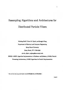
2.1 Schema architecture Figure 2 shows our 7-level schema architecture and the processors used to obtain it: User Schema 12IJ-1
User Schema 11IJ-1
...
...
User Schema 1LIJ-1
...
Transforming Processor
...
Transforming Processor
...
Translated Schema 11I
...
Translated Schema 12I
Translated Schema 111
Translated Schema 121
...
Translated Schema 1LI Translated Schema 1L1
...
User Schema M1IJ || ... Translated Schema M1I User Schema M11J || ... Translated Schema M11
Derivation Processor
...
Derivation Processor
Derivation Processor
Authorization Schema 12 . . .
User Schema MLIJ || Translated Schema MLI User Schema ML1J || Translated Schema ML1
...
...
...
Derivation Processor
UDMs
User Schema 1LI1
...
Transforming Processor
Authorization Schema 11
...
User Schema 1211
User Schema 1111
Derivation Processor
Authorization Schema M1 . . .
Authorization Schema 1L
Security Processor
Authorization Schema ML
Security Processor
Federated Schema 1
...
Federated Schema M
N CDBs M Federated Schemas
L Levels of Integration Processor
Export Schema 1
Export Schema K1
...
Negotiation Processor Component Schema 1
Export Schema K2
Negotiation Processor ...
Conversion Processor Native Schema 1
Integration Processor
Component Schema K
Native Schema K
Export Schema N
I User Views J User Models
Negotiation Processor ...
Conversion Processor ...
...
Security Classification
Component Schema N
CDM
Conversion Processor ...
Native Schema N
NDMs
Figure 2. Construction Architecture The different schemas are: 1. Native Schema: is the Conceptual Schema of a CDB expressed in its native data model. 2. Component Schema: is the conversion of a Native Schema into BLOOM (our CDM). 3. Export Schema: represents the part of a Component Schema that is available to a class of federated users. 4. Federated Schema: is the integration of multiple Export Schemas, each Federated Schema supports one semantics.
5. Authorization Schema: represents a subset of a Federated Schema which is classified at one federated security level. 6. Translated Schema: defines a schema for a user and/or application or a class of users/applications expressed in the CDM. 7. User Schema: is the conversion of a Translated Schema into the user native data model. We have added two additional schema levels to the 5-level architecture by Sheth and Larson: the Authorization and Translated Schema levels. The Authorization Schema level has been added to deal with some security issues that have not explicitly been treated in the reference architecture and remain hidden into the External and Export Schemas. Given we use multilevel security model, each Authorization Schema determines the set of data that a user, according to his clearance, can access. From each Authorization Schema we derive several Translated Schemas and from them we derive User Schemas. In this way we can refuse attempts of non authorized access before a query was submitted to the involved CDBs. On the other hand, the Translated Schema level (taken from [SCRR96]) has been included to separate two issues related to the process of derivation of User Schemas from Federated Schemas in the 5-level architecture. This process consists in fact of two transformations: change in model and change in the contents, corresponding to two processor types: Derivation Processor and Filtering Processor in the terminology of Sheth and Larson. The separation of issues into schema levels and specific processors is not complete in the reference architecture. We present a different architecture, in which the External Schema level is divided into two. The upper level schema of the federated user expressed in his own model is called User Schema; the translation of this User Schema to the CDM is called Translated Schema. The Translated Schema is derived from an Authorization Schema by a Derivation Processor, while the passage from the Translated Schema to the User Schema is done by a Transforming Processor. In this way, the issues and the processors are clearly separated: only one change is made at each step.
2.2 Processors We obtain the different schema levels through a bottom-up process carried out by the following processors: Conversion Processor, Negotiation Processor, Integration Processor, Security Processor, Derivation Processor and Transforming Processor (see figure 2). Firstly, when a federation is formed, it is necessary to use a Conversion Processor to convert Native Schemas into Component Schemas expressed in the CDM of the federation. This conversion includes the semantic enrichment of the Native Schemas and the translation of data structures. At this stage we maintain the data classification which depends on native security levels. The objective of the Conversion Processor is to resolve syntactic heterogeneities and corresponds to the Transforming Processor of Sheth and Larson. In figure 2 we assume that the CDBs do not use the CDM as their native data model. If this was the case, it would be unnecessary to define the Component Schema. Once the Component Schemas have been obtained, a negotiation process is initiated in order to reach an agreement about the portion of data that each CDB exports to the federation, and which part of these data the CDB allows to be read. The negotiation is carried out by the federated and local administrators with the aid of the Negotiation Processor which gives support to the association autonomy, giving as final result a collection of Export Schemas. For example, in figure 2, two Export Schemas have been derived from Component Schema K (belonging to CDBK), whereas just one Export Schema has been derived from Component Schema 1. From Export Schemas of different CDBs one or more Federated Schemas are constructed. This process is performed by an Integration Processor that suggests how integrate the Export Schemas helping to solve semantic heterogeneities and providing distribution transparency. The Integration Processor is placed in the same level that the Constructing Processor in the reference architecture but, whereas the Constructing Processor only gives support to the resolution of the problems related to semantic heterogeneity of data, the Integration Processor also helps to solve semantic heterogeneities
among the set of classification levels (number of levels and their semantics) that each native multilevel security model has. Thus, taking the CDBs in figure 1 we obtain the Federated Schema shown in figure 3 in a graphical form and in the BLOOM definition language. The class customers_db2 (drawn as a doted line oval) has been created during the integration process since this process has detected that the classes producers and receivers in CDB2 are subconcepts of the class customers_db1. In the same way, the class shipments in CDB2 (remind it holds attributes related to the classes waste_db1 and shipments_db1) has been transformed giving rise to the new class wastes_db2 and the modified class shipments_db2 (drawn as a doted and dashed line oval respectively). We do not show classes such producers_db2 or receivers_db2 because this is a minimal Federated Schema; for further information about the process see [GCS96].
_c o
t_
i sc _d db
...
e
f_a dd res s
_ c od
e
f_waste
shipments_db1
shipments_db2
f_customers [U]
e n am ny_ pe mpa y t f _c o _ t en at m r tre sc f_ i _d db
... db_discr
customers_db2
t io ns
f _w
au
f_name
k
r ec
superclass
db_discr
f _p ris
...
role
waste
waste_db1
customers_db1
specialization criteria subclass
...
waste
wastes_db2
f_
component
f _s h
e
f_shipments [U] n pa om ess f _c f _a d d r e t_typ f_t rea tm en f_cu stom er _t yp e db_discr
od e
od
am
c _c
_c
f _r e
pe
cu
er _t yp e
r
f_custom er_type
ty
f_cu stom
r db
en
f_
n y_
f_receivers [U]
at m
...
i sc
om
de
...
...
u st
f_producers [U] tre
r od
f_receiver
f_
f _p
me
f _c
f_ad dress
r
_n a
i sc
an y
_d
mp
_d
db
f _c o
er _
t yp
e
f_producer
de cr di b_
a_ co d
f_wastes [U]
sim ple aggregation
class f_wastes [U] class f_producers [U] class f_customers [U] alt_gen_of f_wastes_db1,f_wastes_db2 [by db_discr] alt_gen_of producers_db1,producers_db2 [by db_discr] alt_gen_of customers_db1,customers_db2 [by db_discr] alt_spec_of f_customers alt_gen_of f_producers,f_receivers [by f_customer_type] simple_aggreg_of db_discr: {db1, db2} simple_aggreg_of simple_aggreg_of f_wa_code: wa_codes db_discr: {db1, db2} [inherited] db_discr: {db1, db2} f_name: strings f_company_name: strings [inherited] f_company_name: strings f_risk: integers [S] f_address: strings [inherited] f_address: strings f_precautions: strings [C] f_treatment_type: tr_codes [inherited] f_customer_type: strings ... f_customer_type: strings [inherited] f_treatment_type: tr_codes id f_wa_code, db_discr f_prod_code: pr_codes [inherited] f_cu_code: cu_codes ... oc: {U, C, S} ... id f_cu_code, db_discr end_class id f_prod_code, db_discr oc: {U, C, S} oc: {U, C, S} end_class end_class class f_receivers [U] alt_gen_of receivers_db1,receivers_db2 [by db_discr] alt_spec_of f_customers simple_aggreg_of db_discr: {db1, db2} [inherited] f_company_name: strings [inherited] f_address: strings [inherited] f_treatment_type: tr_codes [inherited] f_customer_type: strings [inherited] f_rec_code: rec_codes [inherited] ... id f_rec_code, db_discr oc: {U, C, S} end_class
class f_shipments [U] alt_gen_of f_shipments_db1,f_shipments_db2 [by db_discr] simple_aggreg_of db_discr:{db1, db2} f_sh_code: sh_codes f_waste: f_wastes f_producer: f_producers f_receiver: f_receivers ... id f_sh_code, db_discr oc: {U, C, S} end_class
Figure 3. Federated Schema
Given that each CDB has its own multilevel security model it will be necessary to analyze the correspondences among the classification of a specific CDB and the classification in the rest of CDBs in order to establish the degree of similarity among the distinct classification levels of the CDBs. In this manner, the set of security classification levels needed at the federation level is obtained ([P93]). In addition, the equivalence between security levels of the federation and the security levels of each CDB is also obtained and stored in the Dictionary. In our example, CDB1 and CDB2 have three and two classification levels respectively. After Negotiation and Integration Processors the set of classification levels of the federation is established as Secret (S), Confidential (C) and Unclassified (U), with the equivalence between CDBs levels and federation levels shown in table 1. Classification levels CDB1
C
CDB2 Federation
R H
S
P L
C
U
Table 1. Classification Levels Equivalence It is important to note that the process of obtaining the Federated and Export Schemas is not a linear process; it will be necessary that the Integration and Negotiation Processors collaborate in an iterative process where the federated and local administrators participate [OS96]. In figure 2, we have M Federated Schemas (for sake of simplicity we have only shown Federated Schema 1 and Federated Schema M) and, for instance, Federated Schema M has been obtained through the integration of Export Schema K2 and Export Schema N. After obtaining the Federated Schemas, the Security Processor separates each Federated Schema (where we have data structures classified in different levels) in several Authorization Schemas (one per level of data classification). Therefore a specific Authorization Schema contains the portion of available data to an authorized federated user (or group of federated users) to access data at this level. Figure 2 shows L security levels of data classification and the corresponding Authorization Schemas (for each Federated Schema we will have L Authorization Schemas). Going back to the running example, given we have data structures classified in three levels, we will obtain three Authorization Schemas from the Federated Schema. Figure 4 only draws the federated class f_wastes at levels Unclassified, Confidential and Secret respectively, since the remaining classes do not differ from those that have appeared in the Federated Schema. Users authorized at level Secret could query the attribute f_risk whereas users authorized at levels Confidential and Unclassified could not access it due to the fact that f_risk has been classified as Secret. Similarly, the attribute f_precautions could not be consulted at Unclassified level because it has been tagged as Confidential. class a_U_f_wastes [U] alt_gen_of f_wastes_db1,f_wastes_db2 [by db_discr] simple_aggreg_of db_discr: {db1, db2} f_wa_code: wa_codes f_name: strings ... id f_wa_code, db_discr oc: {U, C, S} end_class
Authorization Schema at level U
class a_C_f_wastes [U] alt_gen_of f_wastes_db1,f_wastes_db2 [by db_discr] simple_aggreg_of db_discr: {db1, db2} f_wa_code: wa_codes f_name: strings f_precautions: strings [C] ... id f_wa_code, db_discr oc: {U, C, S} end_class
Authorization Schema at level C
class a_S_f_wastes [U] alt_gen_of f_wastes_db1,f_wastes_db2 [by db_discr] simple_aggreg_of db_discr: {db1, db2} f_wa_code: wa_codes f_name: strings f_risk: integers [S] f_precautions: strings [C] ... id f_wa_code, db_discr oc: {U, C, S} end_class
Authorization Schema at level S
Figure 4. Authorization Schemas The Derivation Processor derives from each Authorization Schema different Translated Schemas in order to specify the part of information in an Authorization Schema that it is relevant to a group of
federated users and/or applications. The main reasons for the use of Translated Schemas are to provide customization and access control. It also helps to pass from External Schemas (expressed in the user data model) to Federated Schema. Figure 2 exhibits I potential user views which are derived from each possible Authorization Schema. Finally, each Translated Schema can be potentially translated from the CDM of the federation to the native model of a determined federated user (or group of federated users) giving rise to several User Schemas. If a federated user is trained in the CDM, then his User Schema would be directly his corresponding Translated Schema. Figure 2 shows J different user data models and points out the two situations discussed above: users that work using their own data model and users that are familiar with the CDM chosen for the federation. For example, part of the users that finally work against Federated Schema 1 use their respective data models (numerated from 1 to J-1) that differ from the CDM (denoted by user data model J). On the other hand, federated users that work with Federated Schema M are trained in the CDM and for this reason their User Schemas and Translated Schemas have been collapsed into one schema. The responsible processor to carry out the passage between Translation and User Schema is a Transforming Processor. Figure 5 only shows one possible Translated Schema at level Secret and its corresponding User Schema expressed in relational model for our example. Due to customization purposes, the class t_a_S_f_shipments has been created by projecting the class a_S_f_shipments in the Authorization Schema at level Secret, while the class t_a_S_f_wastes has not changed from those described in figure 4. class t_a_S_f_shipments [U] alt_gen_of f_shipments_db1,f_shipments_db2 [by db_discr] simple_aggreg_of db_discr:{db1, db2} f_sh_code: sh_codes f_waste: f_wastes ... id f_sh_code, db_discr oc: {U, C, S} end_class
shipment [U] sh_code
waste [U]
waste_code
waste_name
class t_a_S_f_wastes [U] alt_gen_of f_wastes_db1,f_wastes_db2 [by db_discr] simple_aggreg_of db_discr: {db1, db2} f_wa_code: wa_codes f_name: strings f_risk: integers [S] f_precautions: strings [C] ... id f_wa_code, db_discr oc: {U, C, S} end_class
waste_code
risk [S]
db_discr
TC
precautions [C ]
db_discr
TC
Figure 5. Translated and User Schemas at Level S
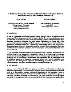
3 The execution architecture When the federation has already been built, a different architecture, called the execution architecture, is in place. Figure 6 depicts this architecture at a functional level, showing all functional software modules and the flow of data from the original query through modules and DBMSs up to the final result. This process may be thought of as a “compile and go” approach, or better as consisting of three steps: 1. Preparation of the query (“compilation”) by the Query Manager (QM) and the Security Manager (SM). 2. Execution of the subqueries (“go”) under control of the Transaction Manager (XM). 3. Production of the final result by the QM. The flow of control and the assignment of modules to sites in the distributed system are not shown in the figure and will be discussed later.
3.1 Data flow The flow of data starts with a query posed by a federal user, in his user site, called Federated Query and shown in the upper left part of figure 6. We assume that the identification and authentication of the user is handled separately by a different process not part of our architecture; issues related to this point will be covered later. The query is first processed by a Security Controller, which makes sure that the query is in accordance with the User Schema of the individual user (USmlij), and therefore authorized at his security level l. If the security control is passed, the query, authorized at security level l, is processed by the Query Transformer, producing an equivalent query expressed in terms of Federated Schema FSm and tagged with security level l. Note that this process is a direct transformation from the User Schema level to the Federated Schema level, skipping the levels of Translated Schemas and Authorization Schemas; this direct transformation is possible because mappings between successive levels of the construction architecture (US - TS, TS - AS and AS - FS) have been combined into direct mapping US - FS and stored in the Directory for use by the Query Transformer. The process of the query is thus expedited. The query, now in BLOOM, expressed in terms of the Federated Schema FSm and tagged with security level l, passes to the Query Decomposer. This processor, making use of the Federated Schema - Component Schemas mappings stored in the Directory, decomposes the query into a number of subqueries, each subquery accessing just one of the CDBs, and expressed in terms of a single Component Schema. We do not exclude that different subqueries of the same query access the same database. Note again that one level, the level of Export Schemas, is skipped, by combining successive mappings into direct mappings, for the sake of improved performance. Federated Query
User schema
D I
mappings among US and FS
R E
mappings among FS and CSs
C T O
mappings among CSs and NSs
R Y
mappings among FSL and CSLs
S E C U R I T Y M A N A G E R
Federated Result
Security Controller
Query Transformer
Query Descomposer
Result Transformer
User schema + mappings
Result Consolidator
Fed. schema + mappings
D I R E C
...
...
... QUERY MANAGER
Query Translator ...
...
Com. schema + mappings
Subresult Translator
O R
...
Y
Level Security Translator ... ...
T
...
...
TRANSACTION MANAGER
Control Sec
DBMS1
DBMS2
DB1
DB2
...
DBMSK
...
DBK
DBMSN
DBN
Figure 6. Execution Architecture The subqueries produced by the Query Decomposer are not isolated: they are connected by a tree. Each node in this Query Execution Tree corresponds to one operation needed to execute the query: leaves for accesses to component databases, the root for producing the final, consolidated result, and intermediate nodes for other operations such as conversions between models and unions and joins of different kinds. The root is generally a result transformation operation, to convert the result into the model and schema of the user, and has a single child node, to perform the result consolidation from partial (sub)results. The form of the intermediate nodes of the tree depends on the query and on the
CDBs, and on the extensional relationships among them, if any; the study of different forms of the tree is out of the scope of this paper. In the simplest case -other than the trivial case accessing just one CDBthere are no other intermediate nodes between the leaves and the result consolidation node. Each node is assigned to a site, and such an assignment is the result of a federal (“global”) optimization performed by this Query Decomposer using data stored in the Dictionary. Some nodes will be allowed to proceed in parallel, while others may have to wait for the result of other operations, but this topic corresponds to control flow, covered in 3.2. In the simplest case no optimization is possible, and all leaves proceed in parallel. Each subquery, in BLOOM, expressed in terms of a Component Schema and always tagged with security level l, is processed by a Query Translator, to yield an equivalent subquery, now in the native data model of the CDB, expressed in terms of the corresponding Native Schema and tagged with (federal) security level l. The Query Execution Tree is updated to have these new subqueries as leaves and to incorporate operations to translate between BLOOM and the native models. The last processor of this first or “compilation” step is the Level Security Translator. A subquery enters this processor tagged with a federal security level l, and must leave with the tag in the component security level of its CDB that corresponds to that federal level, in accordance with what was agreed during the negotiation and integration phases, as stored in the Dictionary in the form of mappings between federal security levels and component security levels. The leaves of the Query Execution Tree become tagged with these component security levels. In the case of the example, assume a user at site 1 with security level Secret poses the following query in terms of the User Schema of figure 5: SELECT * FROM shipments, wastes WHERE shipments.waste_code = wastes.waste_code
The resulting Query Execution Tree (data flow goes bottom-up) is shown in figure 7: Relational Model/User Schema at site 1
Result Transformation BLOOM/Federated Schema at site 1
Result Consolidation (discriminated generalization) BLOOM/Component Schema at site 1
Conversion from
Subresult shipping
relational to BLOOM
from site 2 to site 1
Relational/Native Schema of CDB1 at site 1
Relational Query
Component Schema=Native Schema of CDB2 at site 2
BLOOM Query Security Level C
Security Level H
DBMS1
DBMS2
CDB1
CDB2
Figure 7. Query Execution Tree The Query Execution Tree is now ready for execution, under control of the XM. This functional module (as well as the QM and the SM) is physically replicated. The previous step has been managed by the QM and SM of the user site where the original Federated Query was posed. The Query
Execution Tree flows from the QM to the XM at that site, where it is decomposed into subtrees, and each subtree is sent to the replica of the XM at the site assigned to its root. The order in which the operations in the tree are executed by the XM is covered in 3.2, when discussing the control flow. Each leave becomes eventually ready to start, i.e. the subquery is to be passed to the DBMS for execution, and two possibilities may exist, from the security point of view. If the DBMS trusts not only the identification and authentication mechanism, but the whole federal system (software modules, directory, communications), then no further security control is needed and the subquery passes to the DBMS for processing. On the contrary, if the DBMS wants to perform its own security control of the individual user, it looks up at its security tables to ensure that the (sub)query is authorized for the user, before processing it. This is done by a Control Security, shown in figure 6 for CDBK. This means that in the first case the DBMS does not know the identity of the federal user, and the (sub)query appears to it as from a generic “federal user” of the corresponding Federated Schema FSm (at a specific level), while in the second case the identity of the federal user has been preserved during the whole preparation step to be passed to the DBMS at this point. The DBMS processes the subquery, which it considers as an ordinary query, and produces a result. This result, from the federal system point of view, is a subresult to be combined with others to produce the final result. Let us now briefly explain this third step of the process of the query. Each subresult proceeds up the Query Execution Tree from the leave to its parent node, that is, is sent from the site assigned to the leave to the site assigned to its parent, unless both are the same site. In the simplest case, (sub)results are directly sent from the XM -at the site of the DBMS accessed- to the XM at the user site, and then to the QM, specifically to the Subresult Translator module (see figure 6) for conversion to BLOOM using the mappings between native and component schemas. In complex cases, the flow of data, flow of (sub)results in this third step, proceeds up the tree through intermediate nodes: each operation receives its operand(s) from its child node(s) and sends its result from its site to the site assigned to its parent node, as needed, until eventually they leave the XM and reach the Subresult Translator. Output from the Subresult Translator is passed to the Result Consolidator, to produce the final result in BLOOM, and Component-Federated Schemas mappings are used. The discriminated union operator [GCS96] may be used to consolidate subresults without lose of information. Finally, the Result Transformer module, using Federated - User Schema mappings, performs the operation at the root of the tree and yields the final result in the user model, expressed in terms of his User Schema, and sends it to him. sh_code 0111
waste_code 060101
db_discr DB2
waste_name Sulphuric Acid
risk 3
0111
060105
DB1
Nitric Acid
3
precautions Neutralize with a base Explosive; keep cool
TC S S
Figure 8. Query Result at Security Level S sh_code waste_code db_discr 0111 060101 DB2 0111 060105 DB1
waste_name Liquid Liquid
Figure 9. Query Result at Security Level U Figure 8 shows the result of the query above whereas figure 9 shows the result of the same query posed by a user with security level U.
3.2 Control flow and site assignments The QM is the main module in charge of managing any query, apart from the XM. Before being controlled by the QM, a query is handled by a User Interface module, which interacts with users and in case what the user entered is a federal query, passes it to the QM. It is this QM which manages the first and third steps of the flow of the query explained in 3.1. Particularly, the QM calls the identification/authentication module (not shown in figure 6), the SM -specifically its submodules Security Controller and Level Security Translator-, and its own submodules Query Transformer, Query Decomposer, Query Translator, Subresult Translator, Result Consolidator and Result Transformer. It also calls the XM to execute the Query Execution Tree. These calls are not shown in figure 6, in order to keep it not too complex. According to the terminology of [S78], in a distributed system supporting accesses to databases, a site may or may not be an access point, and may or may not be a storage point. In our case, a site accepting federal queries is an access point, while component databases are located in storage points. The QM must be distributed, with a replica of it in every access point, since federal queries are managed at the user site, as explained above. The XM is responsible for executing the Query Execution Tree prepared by the QM, and for returning (sub)results to the QM. It must be distributed, with a replica of it at least in every access point, since it is called locally from the QM at the user site. In addition, every storage point should have a replica of the XM to manage leaves of the Query Execution Tree and their (sub)results, but it is possible that some sites retain such a degree of autonomy that they do not allow the placement of modules of the federal system. In such a case, a replica of the XM at another site will be in charge of managing operations and results of the site, and what we will call “the XM at the CDB site” will not physically be at the site of the CDB. For a given query, the XM at the user site prepares subtrees of the Query Execution Tree and calls the XM of the site assigned to the root of each subtree, sending it a copy of the subtree. These XMs receive their subtrees and manage their execution, according to the form of the each subtree. For a given subtree, and at some specific point in time, some of its subtrees may be already completed, some executing in parallel, and some waiting for intermediate results as input; the XM receives partial results and dispatches waiting subtrees as needed, until all its subtrees have finished and passes control to the XM of the site of its parent node, sending its (sub)result to it. The overall result may not correspond to an ACID transaction (because of a possible Non repeatable Read interference), but this topic is outside the scope of this paper. If the form of the Query Execution Tree is the simplest one, then the replicas of the XM manage only leaves, corresponding to accesses to the CDBs. All these operations proceed in parallel, and their (sub)results are sent to the QM at the user site, specifically to the Subresult Translator.
4 Conclusions and future work We have shown a 7-level schema architecture and a functional architecture for tightly federated database systems. With respect to our schema architecture, we have presented the Authorization Schema level and have pointed out how this level could contribute to develop a solution to deal with multilevel security aspects. Our work is only the beginning of more research that needs to be done in order to treat security and access control in the context of federated database systems. We are currently working on how the analysis and resolution of conflicts among different classification levels in several CDBs could be incorporated into the integration process and how the Integration Processor must collaborate with the Negotiation Processor to obtain both the Export and Federated Schemas. On the other hand, we have sketched the main modules of the execution architecture. Our immediate work along this line includes the study of different forms of the query execution tree and a decomposition strategy of federated queries into several subqueries.
Acknowledgments This work has been partially supported by the Spanish PRONTIC program, under project TIC960903 and by the European Research Consortium for Informatics and Mathematics (ERCIM) under project CHRX-CT94-0531.
References [BE96]
O. Bukhres & A. Elmagarmid (eds.): Object Oriented Multidatabase Systems. PrenticeHall,1996.
[CSG94]
M. Castellanos, F. Saltor & M. García-Solaco: A Canonical Data Model for the Interoperability among Object-Oriented and Relational Databases. In Özsu, Dayal and Valduriez (eds), Distributed Object Management, pages 309-314, Morgan Kaufmann, 1994.
[DJ94]
K.R. Dittrich & D. Jonscher: “Current Trends in Database Technology and Their Impact on Security Concepts”. In J. Biskup, M. Morgenstern, & C.E. Landwehr (eds), Database Security, VIII (A-60), Elsevier Science B.V. (North-Holland), pages 11-33, 1994.
[GCS96]
M. García-Solaco, M. Castellanos & F. Saltor: “A Semantic-Discriminated Approach to Integration of Federated Databases”. In Laufmann, Spaccapietra & Yokoi (eds.): Proc. 3rd Int. Conf. On Cooperative Information Systems (CopIS’95, Vienna), Univ. of Toronto, 1995.
[P93]
G. Pernul: “Canonical Security Modeling for Federated Databases”. In Hsiao, Neuhold & Sacks-Davis (eds): Interoperable Database Systems (DS-5). (Proc. of the IFIP WG2.6 Database Semantics Conference on Interoperable Database Systems (DS-5), Lorne, Victoria, Australia, November 1992). IFIP Transactions A-25. North-Holland, 1993.
[P94]
G. Pernul: “Database Security”. In M. C. Yovits (ed.): Advances in Computers, vol 38. Academic Press, 1994.
[OS96]
M. Oliva & F. Saltor: “A Negotiation Process Approach for Building Federated Databases”. In 10th ERCIM Database Research Group Workshop on Heterogeneous Information Management, Prague 1996, ERCIM-96-W003 ERCIM, pages 43-49, 1996.
[SCRR96] F. Saltor, B. Campderrich, E. Rodríguez & L.C. Rodríguez: “On Schema Levels for Federated DB Systems” In Yetongnon and Hariri (eds), Proceedings of the ISCA International Conference on Parallel and Distributed Computing Systems (PDCS’96, Dijon), ISCA, pages 766-771, 1996. [SL90]
A. Sheth & J. Larson: "Federated Database Systems for Managing Distributed, Heterogeneous and Autonomous Databases". ACM Computing Surveys, Vol.22, No.3, (Sept. 90).
[S78]
S. Spaccapietra: Problematique de Conception d’un Système de Gestion de Bases de Données Reparties. Thèse d’état, Univ. Pierre et Marie Curie (Paris VI), 1978.