INTERNATIONAL JOURNAL FOR NUMERICAL METHODS IN ENGINEERING Int. J. Numer. Meth. Engng 2016; 105:403–415 Published online 21 July 2015 in Wiley Online Library (wileyonlinelibrary.com). DOI: 10.1002/nme.4973
On the application of higher-order elements in the hierarchical interface-enriched finite element method Soheil Soghrati1,2,3,*,† and Jorge L. Barrera1 1 Department
of Mechanical and Aerospace Engineering, The Ohio State University, Columbus, OH, USA of Materials Science and Engineering, The Ohio State University, Columbus, OH, USA 3 Simulation Innovation and Modeling Center, The Ohio State University, Columbus, OH, USA
2 Department
SUMMARY This article introduces a new algorithm for evaluating enrichment functions in the higher-order hierarchical interface-enriched finite element method (HIFEM), which enables the fully mesh-independent simulation of multiphase problems with intricate morphologies. The proposed hierarchical enrichment technique can accurately capture gradient discontinuities along materials interfaces that are in close proximity, in contact, and even intersecting with one another using nonconforming finite element meshes for discretizing the problem. We study different approaches for creating higher-order HIFEM enrichments corresponding to six-node triangular elements and analyze the advantages and shortcomings of each approach. The preferred method, which yields the lowest computational cost and highest accuracy, relies on a special mapping between the local and global coordinate systems for evaluating enrichment functions. A comprehensive convergence study is presented to show that this method yields similar convergence rate and precision as those of the standard FEM with conforming meshes. Finally, we demonstrate the application of the higher-order HIFEM for simulating the thermal and deformation responses of several materials systems and engineering problems with complex geometries. Copyright © 2015 John Wiley & Sons, Ltd. Received 4 October 2014; Revised 7 June 2015; Accepted 9 June 2015 KEY WORDS:
HIFEM; hierarchical enrichment; higher-order elements; materials interface; porous media; pitting corrosion
1. INTRODUCTION Regardless of the underlying physics, a key challenge in performing standard FEM simulations is to construct an appropriate discretized model for problems with complex morphologies [1]. This process involves modeling the problem geometry via computer-aided design drawings or importing that from imaging data such as computed tomography, followed by the construction of an appropriate conforming finite element (FE) mesh. The quality of this conforming FE mesh, that is, its refinement level and aspect ratio of elements, has a crucial impact on the accuracy and stability of the FEM approximation [2–5]. Even with the aid of state-of-the-art commercial software packages, creating such conforming meshes can be a laborious and challenging task for problems with intricate microstructures such as composites and heterogeneous materials systems. The complexity of this process increases even further when dealing with problems with evolving morphologies such as transient phenomena and design optimization studies, which require the automated regeneration of FE meshes or their adaptive refinement throughout the simulation [6–8]. To address these challenges in implementing the standard FEM for simulating problems with complex geometries, a broad spectrum of research has been directed towards developing alterna*Correspondence to: Soheil Soghrati, Department of Mechanical and Aerospace Engineering, Department of Materials Science and Engineering, The Ohio State University, 201 W. 19th Avenue, Columbus, OH 43210, USA. † E-mail:
[email protected] Copyright © 2015 John Wiley & Sons, Ltd.
404
S. SOGHRATI AND J. L. BARRERA
tive numerical techniques such as BEM [9–11], meshfree methods [12–15], and mesh-independent FEMs [16–18]. The extended/generalized FEM [19, 20], one of the most popular methods in the latter category, has successfully been applied to a variety of engineering problems with strong and weak discontinuities, that is, problems with discontinuities in the solution and gradient fields, respectively [21, 22]. The interface-enriched generalized FEM (IGFEM) [23] is another meshindependent technique that implements enriched DOFs along materials interfaces to simulate the discontinuous phenomena. Applications of this method to the modeling and computational design of various engineering problems are presented in [24–27]. However, a major limitation of the IGFEM is the inability to automatically enrich nonconforming elements cut by multiple materials interfaces, which can frequently occur in modeling multiphase problems with interfaces that are in close proximity or contact (e.g., heterogeneous materials and composites). Recently, Soghrati has introduced the hierarchical interface-enriched FEM (HIFEM) [28], which completely obviates the shortcomings of the IGFEM for modeling multiphase problems with complex geometries. This fully mesh-independent technique yields a similar level of accuracy and convergence rate as the standard FEM, while providing a general and yet easy-to-implement algorithm for evaluating appropriate enrichment functions in elements cut by any number and configuration of materials interfaces. However, the work presented in [28] only addresses the construction of HIFEM enrichments and their performance for problems discretized using three-node triangular FE meshes. Because these linear elements yield a poor performance for simulating the stress field in structural problems (due to deficiencies such as shear locking [29]), the use of higherorder elements is often the preferred choice for modeling such problems. In this work, we study different approaches for the construction of HIFEM enrichment functions associated with six-node triangular Lagrangian elements and present a convergence study to shed light on the performance of higher-order elements in HIFEM. It must be noted that although the current manuscript is focused on the implementation of quadratic elements in HIFEM, the proposed algorithm can easily be expanded to other types of higher-order Lagrangian elements. The remainder of this article is structured as follows. Section 2 presents the weak forms of the conductive heat transfer and linear elasticity problems, together with a brief overview of the HIFEM formulation for three-node triangular elements. In Section 3, we present the higher-order HIFEM algorithm and discuss different approaches for constructing hierarchical enrichments in this method, which is followed by a convergence study in Section 4. Section 5 demonstrates the application of the higher-order HIFEM for simulating the thermal and deformation responses of three example problems with intricate geometries. 2. PROBLEM FORMULATION 2.1. Governing equations N composed of m different material phases Consider an open domain ! ! R2 with closure ! N 2::: [ ! N m . The domain boundary N N1 [ ! corresponding to non-overlapping partitions ! D ! N @! D ! n ! D "D [ "N with outward unit normal vector n is divided into two distinct regions ("D \"N D ;) corresponding to Dirichlet and Neumann boundary conditions, respectively. DecomN ! R such that ud j!D D uN N ! R into u D u0 Cud , where ud W ! posing the temperature field u W ! (uN W "D ! R), is the prescribed temperature on "D ; the weak form of® the conductive heat transfer¯ N equation in ! can be written as follows: Find u0 D [m i D1 u0i 2 V WD u0i W !i ! R; u0 j!D D 0 such that m Z X i D1
"i
r.u0 C ud / " !i rv d ! C
Z
"
vQ d ! C
Z
!q
vq d" D 0 8v 2 V ;
(1)
N i ! R2 #R2 is the thermal conductivity tensor associated with the i-th material phase, where !i W ! Q W ! ! R is the heat source, and q W "N ! R is the applied heat flux. The temperature and heat Copyright © 2015 John Wiley & Sons, Ltd.
Int. J. Numer. Meth. Engng 2016; 105:403–415 DOI: 10.1002/nme
HIGHER-ORDER HIERARCHICAL INTERFACE-ENRICHED FINITE ELEMENT METHOD
405
N j with N i and ! flux continuity conditions along the interface between two adjacent subdomains ! outward normal vectors ni and nj , respectively, are written as on
uj!i $ uj#j D 0
!i ru " ni C !j ru " nj D 0
on
!i \ !j ; !i \ !j :
(2)
N ! Similarly, assuming u D u0 Cud as the deformation response of a continuum such that ud W ! 2 R and ud j!D D uN (uN W "D ! R is the prescribed displacement), the weak form of the ¯linear ® N ! R2 ; u0 j!D D 0 such elasticity problem can be expressed as follows: Find u0 2 W WD u0 W ! that Z Z m Z X T T L.u0 C ud / " Ci L w d ! C wb d ! C wNf d" D 0 8w 2 W ; (3) 2
i D1
"i
"
!f
where Ci denotes the fourth-order elasticity tensor associated with the i-th material phase, b W ! ! R2 is the body force, and Nf W "N ! R2 is the applied traction vector. The differential operator L is given by " # @ @ 0 L D @x @ @x : (4) @ 0 @y @y N j is written as N i and ! The continuity of displacement and tractions along the interface between ! T
T
uj!i $ uj!j D 0 T
on
T
Ci L u " ni $ Cj L u " nj D 0
on
!i \ !j ; !i \ !j :
(5)
Assuming Ei W !i ! R as the elastic modulus and #i W !i ! R as the Poisson ratio of each material phase, Ci for a plane stress elasticity problem is given by 2
1 #i Ei 4 #i 1 Ci D 1 $ #i2 0 0
3 0 0 5:
1!$i 2
(6)
Finally, the Galerkin approximations uh of (1) and uh of (3) are evaluated by replacing V and W with appropriate finite dimensional spaces V h ! V and W h ! W , respectively (e.g., the space of Lagrangian shape functions). 2.2. Hierarchical interface-enriched finite element method formulation In this section, we provide a brief overview of the HIFEM algorithm for approximating (1) using linear triangular elements, as originally presented in [28]. Expanding this formulation to (3) is straightforward and thus has not been discussed in this section. Discretizing the domain ! Š !h using a nonconforming (non-matching) mesh, the HIFEM approximation uh of (1) is given by uh D
n X i D1
Nip ui C
ne n X
sj.h/
.h/ .h/ j ˛j ;
(7)
j D1
where the first term corresponds to the standard FEM approximation and the second term is the contribution of enrichment functions to capture gradient discontinuities. In (7), ui is the value of the temperature at the i-th node of the nonconforming element, ˛j.h/ is the generalized DOF associated with the j -th interface node created at the intersection point of the h-th materials interface n with element edges, and ¹Nip ºniD1 and ¹ j.h/ ºnj eD1 are sets of n Lagrangian shape functions and Copyright © 2015 John Wiley & Sons, Ltd.
Int. J. Numer. Meth. Engng 2016; 105:403–415 DOI: 10.1002/nme
406
S. SOGHRATI AND J. L. BARRERA
Figure 1. Schematic process of constructing children elements and hierarchical interface-enriched FEM hierarchical enrichments in a nonconforming three-node triangular element cut by two materials interfaces: (a) Root element cut by two materials interfaces; (b,c) children elements and interface nodes created at the first and second levels of hierarchy, respectively; (d,e) enrichment functions associated with the first and second levels of hierarchy, respectively; and (f) combined enrichment function.
ne n hierarchical enrichment functions, respectively. Also, sj.h/ is a scaling factor that ensures the construction of a well-conditioned stiffness matrix. The algorithm used for evaluating this scaling factor is similar to that presented in [30]. This reference also provides a detailed discussion on the impact of the scaling factor on the condition number of the stiffness matrix. Figure 1 schematically shows the process of creating HIFEM enrichments in a nonconforming three-node triangular element to capture weak discontinuities along two materials interfaces that intersect with the element edges. To evaluate the enrichment function j , the first step is to hierarchically discretize the nonconforming (parent) element into smaller integration (children) sub-elements that conform to each materials interface. In this approach, children elements created because of the intersection between the first interface and the element edges are labeled as the first level of hierarchy, which serve as parent elements for creating children elements associated with the second materials interface. This hierarchical discretization scheme is continued until all interfaces that cut the original parent element (root element) are visited. Note that the sequence of visiting materials interfaces for constructing children elements in this recursive algorithm does not affect the accuracy of HIFEM. Assuming nhl as the number of hierarchical levels (i.e., the number of materials interfaces within the root element), the total enrichment function is computed as
total
D
nhl X
hD1
.h/
h
D
.h/
nin nc nhl X X X
Nrk ;
(8)
hD1 j D1 kD1
.h/ is the number of where n.h/ in is the number of interface nodes at the h-th hierarchical level, nc k children elements connected to the j -th interface node at this level, and Nr is the r-th Lagrangian shape function of the k-th child element connected to node j at the same level of hierarchy. For more details regarding the HIFEM formulation, together with the required considerations for performing numerical quadrature in hierarchical children elements, refer to [28].
3. HIGHER-ORDER HIFEM ALGORITHM In this section, we present the HIFEM formulation for simulating multiphase problems discretized using six-node triangular elements. While the recursive algorithm described in Section 2.2 for evaluating hierarchical enrichments remains unchanged, the construction of children elements and their Copyright © 2015 John Wiley & Sons, Ltd.
Int. J. Numer. Meth. Engng 2016; 105:403–415 DOI: 10.1002/nme
HIGHER-ORDER HIERARCHICAL INTERFACE-ENRICHED FINITE ELEMENT METHOD
407
Figure 2. Two different approaches for constructing children elements of a six-node triangular parent element cut by a single materials interface. (a) Nodes 4 and 6 of the parent element do not belong to any of the children elements. (b) All parent nodes are used in creating children elements.
basis functions in such elements must be modified to take into account the effect of midpoints of the parent element. Note that three-node triangular elements should not be used as children elements for evaluating enrichments in higher-order FE meshes, as they fail a simple patch test of reconstructing a linear field with gradient discontinuities. This is because some polynomial terms of higher-order Lagrangian shape functions of the root element (e.g., the terms x 2 and y 2 in a quadratic shape function) cannot be eliminated by similar terms using linear enrichments; consequently, the approximate solution cannot simulate a linear field. Thus, one must implement higher-order elements as children elements to compute appropriate hierarchical enrichments in problems discretized with six-node triangular elements. Figure 2 illustrates two different schemes for constructing six-node children elements in a nonconforming element cut by a single materials interface. In the first approach (Figure 2(a)), noncorner nodes 4 and 6 of the parent element are not incorporated in constructing children elements. Instead, two new enriched nodes (shown as red rectangles) are created at midpoints of children element edges, which leads to a total number of eight enriched nodes. While this approach can theoretically pass the patch test and is easy to implement, detaching nodes 4 and 6 from children elements and creating two additional enriched nodes lead to a higher number of DOFs and thus reduced computational efficacy. However, the main disadvantage that completely hinders the implementation of this approach is the formation of a singular stiffness matrix due to redundant enriched DOFs, which cause linear dependency with those of the parent element. The formation of a singular stiffness matrix can be avoided by implementing midpoints of the parent element in constructing children elements, as shown in Figure 2(b). However, because such nodes are no longer located in the middle of the child element edges, even for parent elements with straight edges and in the presence of straight materials interfaces, this approach yields distorted children elements with non-constant Jacobian determinants when using a standard isoparametric formulation. Because the HIFEM allows interfaces to cut the parent element edges at arbitrary locations, the element distortion can be severe when the intersection point is close to one of the nodes of the parent element. This can result in a considerably higher computational cost because: (1) more integration points are needed to perform accurate quadrature in distorted elements [31]; and (2) due to the non-constant Jacobian determinant of distorted children elements, a nonlinear problem must be solved iteratively at each quadrature point to evaluate the local coordinates of its corresponding point in the parent element [28]. In addition to imposing higher computational cost, this can also deteriorate the HIFEM accuracy if an inadequate number of Gauss points are used for numerical integration. To eliminate the difficulties associated with the formation of distorted children elements in the higher-order HIFEM, we propose a new approach for evaluating the enrichment functions of such elements. In this approach, which is schematically shown in Figure 3, we implement a special mapping for creating the reference element associated with a distorted child element. This mapping maintains a constant value for the ratio of distance between non-corner and corner nodes on each edge of the child element to the length of that edge in both the local and global coordinate systems. For example, in Figure 3, this mapping must satisfy the relation $2 D LL2 in both coordinate systems. The enrichment functions associated with this special mapping are not only functions of Copyright © 2015 John Wiley & Sons, Ltd.
Int. J. Numer. Meth. Engng 2016; 105:403–415 DOI: 10.1002/nme
408
S. SOGHRATI AND J. L. BARRERA
Figure 3. Special mapping of a six-node triangular child element from the global coordinate system (left) to the reference element in the local coordinate system (right) for evaluating hierarchical interface-enriched FEM enrichment functions. The parameters $1 , $2 , and $3 are ratios of distance between non-corner and corner nodes of each edge to the length of that edge, which are kept constant in both the local and global coordinate systems.
Figure 4. Hierarchical process of creating higher-order children elements for evaluating enrichment functions in a nonconforming six-node triangle cut by two materials interfaces: (a) configuration of materials interfaces and (b,c) children elements created at the first and second levels of hierarchy, respectively.
local coordinates .%; &/ but also functions of the length scales $1 , $2 , and $3 shown in Figure 3. The resulting enrichment functions can be written as .% C & $ 1/.$2 % $ $1 $2 C $1 &/ ; $1 $2 $%.$3 % $ $1 $3 $ & C $1 & C $3 %/ N2 D ; $3 .$1 $ 1/ .$2 & $ &2 /.$2 $ 1/ C %&.$2 $ $3 / N3 D ; .$2 $ 1/.$3 $ 1/
N1 D
%.% C & $ 1/ ; $1 .$1 $ 1/ $%& N5 D ; $3 .$3 $ 1/ &.% C & $ 1/ N6 D : $2 .$2 $ 1/ N4 D
(9)
The proposed mapping yields distorted children elements with constant Jacobian determinants for problems with straight materials interfaces. Otherwise, the distortion of children elements will be minimal and only due to the curvature of the materials interface rather than inappropriate locations of their midpoints. It must be noted that the parametric shape functions given in (9) can also be computed for each element in the global coordinate system. However, this pre-computed parametric representation facilitates the numerical quadrature and can be easily incorporated in the HIFEM implementation to reduce the computational cost associated with constructing enrichment functions. Using a similar recursive algorithm as that described in Section 2.2, one can hierarchically create higher-order children elements and use the mapping scheme described earlier to evaluate HIFEM enrichments using (9) at each level of hierarchy. Figure 4 schematically illustrates this process for a nonconforming six-node element cut by two materials interfaces. 4. CONVERGENCE STUDY In this section, we study the convergence rate of the second-order HIFEM for simulating two multiphase problems (one thermal and one structural) with straight and curved materials interfaces, respectively. All simulations are conducted using nonconforming structured (background) meshes Copyright © 2015 John Wiley & Sons, Ltd.
Int. J. Numer. Meth. Engng 2016; 105:403–415 DOI: 10.1002/nme
HIGHER-ORDER HIERARCHICAL INTERFACE-ENRICHED FINITE ELEMENT METHOD
409
Figure 5. First convergence study problem: (a) domain geometry and boundary conditions; (b) hierarchical interface-enriched FEM approximation of the temperature field using a 16 # 8 structured mesh. The inset of (a) illustrates hierarchical interface-enriched FEM children elements created at the highest level of the hierarchy.
composed of six-node triangular elements for discretizing the bounding box of the domain. To shed light on the accuracy and convergence rate of this method, we examine the variations of the L2 and H 1 norms of the error defined as sZ ! ! !u $ uh !2 d !; EL2 .!/ D "
EH 1 .!/
D
sZ
"
"! ! ! # ! !u $ uh !2 C !ru $ ruh !2 d !:
(10)
4.1. Thermal problem with straight materials interfaces In this first example problem, we investigate the performance of six-node triangular elements for the HIFEM simulation of the conductive heat transfer in an adhesive bonded joint, as shown in Figure 5(a). Thermal conductivities of steel adherends and the adhesive layer are 'st D 50:0 W/(m K) and 'ad D 1:00 W/(m K), respectively. Boundary conditions of the domain consists of prescribed temperatures uN D 0 ı C and uN D 100 ı C along the bottom and top edges, respectively, while the side edges are insulated. A linearly varying heat source of Qst D 120y W/m2 is also applied to the adherends (Qad D 0 W/m2 ). The analytical solution for the temperature field is given by T D $0:4y 3 C 43:83y T D 568:9y $ 2786:7 3
T D $0:4y C 45:09y C 49:14
0 cm 6 y 6 5.2 cm 5.2 cm 6 y 6 5.3 cm
(11)
5.3 cm 6 y 6 10 cm:
The HIFEM approximation of the temperature field using a 16 # 8 structured mesh for discretizing the domain is depicted in Figure 5(b). This figure also illustrates the temperature profile in the y direction, which clearly demonstrates the ability of the second-order HIFEM to capture gradient discontinuities along both materials interfaces. Variations of the L2 and H 1 norms of the error associated with the second-order HIFEM approximation of the temperature field versus the element size (h) are presented in Figure 6. Four nonconforming structured meshes with resolutions 8 # 4, 16 # 8, 32 # 16, and 64 # 32 are used to discretize the domain. Given the location of the adhesive layer in this problem (Figure 5(a)), the middle row of elements in all meshes is cut by both the upper and lower adhesive–adherend interfaces. As shown in Figure 6, the HIFEM yields similar rates of convergence to those of the second-order standard FEM with conforming meshes in both norms of the error (optimal convergence rates for EL2 ."/ and EH 1 ."/ are 3 and 2, respectively). Copyright © 2015 John Wiley & Sons, Ltd.
Int. J. Numer. Meth. Engng 2016; 105:403–415 DOI: 10.1002/nme
410
S. SOGHRATI AND J. L. BARRERA
Figure 6. First convergence study problem: variations of the L2 and H 1 norms of the error versus the element size (h) for the second-order hierarchical interface-enriched FEM approximation of the temperature field in the domain shown in Figure 5(a). The triangles depicted in this figure correspond to optimal convergence rates of the second-order standard FEM. The hierarchical interface-enriched FEM convergence rates shown on the top of each triangle are computed based on the last two data points.
Figure 7. Second convergence study problem: (a) domain geometry, materials properties, and boundary conditions; (b,c) second-order hierarchical interface-enriched FEM approximations of the stress field in x and y directions using an 80 # 80 structured finite element mesh for discretizing the domain.
4.2. Structural problem with curved materials interfaces In this example, we compare the accuracy and convergence rates of the second-order HIFEM with those of the standard FEM for simulating the deformation response of the plane stress problem shown in Figure 7(a). The 100 (m # 100 (m domain consists of an aluminum matrix (Eal D 70 GPa, #al D 0:334) with embedded iron (Efe D 200 GPa, #fe D 0:17) and silicon (Esi D 160 GPa, #si D 0:28) circular inclusions. A compressive uniform load of fN D 50 kN/m is applied along the top edge of the domain, while its bottom edge is constrained against horizontal and vertical displacements. Figure 7(b) and (c) illustrate the second-order HIFEM approximations of the normal stress fields in the x and y directions, respectively, using an 80 # 80 structured mesh of six-node triangular elements for modeling the problem. As shown in the inset of Figure 7(a), because of the close proximity of embedded inclusions and regardless of the level of mesh refinement, several nonconforming elements are cut by two materials interfaces in the discretized model. Variations of the L2 and H 1 norms of the error versus h for the second-order HIFEM and standard FEM approximations of the deformation response of this problem are depicted in Figure 8. Five structured FE meshes with resolutions 10 # 10, 20 # 20, 40 # 40, 80 # 80, and 160 # 160 are used to discretize the domain for performing HIFEM simulations. Conforming FE meshes with Copyright © 2015 John Wiley & Sons, Ltd.
Int. J. Numer. Meth. Engng 2016; 105:403–415 DOI: 10.1002/nme
HIGHER-ORDER HIERARCHICAL INTERFACE-ENRICHED FINITE ELEMENT METHOD
411
Figure 8. Comparison between variations of the L2 and H 1 norms of the error versus the element size (h) for the second-order hierarchical interface-enriched FEM (HIFEM) and standard FEM simulations of the deformation response of the second convergence study problem (shown in Figure 7(a)). The triangles depicted in this figure correspond to optimal convergence rates of the second-order standard FEM. The HIFEM convergence rates shown on the top of each triangle are computed based on the last two data points.
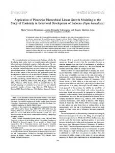
similar levels of refinement are used in the standard FEM analyses, although creating more refined elements in the vicinity of the inclusions that are in close proximity is inevitable. Because no analytical solution exists for this problem, a second-order standard FEM approximation using a highly refined conforming mesh with max.h/ ' 0:12 (m (688,731 elements) is adopted as the reference solution for computing errors. As shown in Figure 8, the HIFEM maintains a similar precision and convergence rate as those of the standard FEM in both norms of the error, while allowing the use of simple structured meshes for discretizing the domain. 5. APPLICATION PROBLEMS In this section, we demonstrate the application of the second-order HIFEM for simulating the thermal and deformation responses of three engineering problems with complex morphologies. All simulations are conducted using nonconforming structured background meshes composed of six-node triangular elements. 5.1. Porous media: thermal and mechanical responses In this example problem, we implement the HIFEM to evaluate the thermal response and the stress field in two domains of a porous titanium foam, as shown in Figures 9(a) and 10(a), respectively. The titanium has a thermal conductivity 'ti D 21:9 W/(m K), an elastic modulus Eti D 110 GPa, and a Poisson ratio #ti D 0:33. To construct HIFEM models of this porous microstructure, circular-shaped pores are hierarchically added to the 100#100 background structured FE mesh at arbitrary locations, resulting in pores that are located in close proximity and even overlapping with one another, as depicted in the insets of Figure 10(a). Boundary conditions of the thermal problem consist of a fixed temperature uN D 100 ı C along the side edges, a constant heat flux qN D 170 W/m2 along the bottom edge, and a convective boundary along the top edge with the heat transfer coefficient hN D 20 W/(m2 K) and the ambient temperature u1 D 21 ı C (Figure 9(a)). The HIFEM approximation of the temperature field in the porous titanium domain is illustrated in Figure 9(b). Note that the HIFEM can easily handle Dirichlet boundary conditions along the side edges of the domain [23]. In the plane stress problem defined on the porous titanium domain shown in Figure 10(a), both horizontal and vertical displacements are constrained along the bottom edge, while a uniform normal traction of fN D 3:5 kN/m is applied along the side edges. The HIFEM approximations of the deformation response, together with the normal stress in the x direction and shear stress fields, are Copyright © 2015 John Wiley & Sons, Ltd.
Int. J. Numer. Meth. Engng 2016; 105:403–415 DOI: 10.1002/nme
412
S. SOGHRATI AND J. L. BARRERA
Figure 9. First application problem: (a) 4.5 mm # 4.5 mm porous titanium domain and boundary conditions of the thermal problem and (b) second-order hierarchical interface-enriched FEM approximation of the temperature field.
Figure 10. First application problem: (a) 5 mm # 5 mm porous titanium domain and boundary conditions of the plane stress linear elasticity problem and (b,c) second-order hierarchical interface-enriched FEM approximations of normal and shear stress fields, respectively.
depicted in Figure 10(b) and (c), respectively. As shown in that figure, the second-order HIFEM can successfully capture sites of stress concentration in the vicinity of materials interfaces. 5.2. Pitting corrosion induced stress concentrations Pitting corrosion is a major concern in high-strength alloys such as stainless steel, which initiates and propagates because of the localized attack of aggressive anions (e.g., chloride) on the material surface [32, 33]. Corrosion pits induce stress concentrations and thus serve as sites of crack Copyright © 2015 John Wiley & Sons, Ltd.
Int. J. Numer. Meth. Engng 2016; 105:403–415 DOI: 10.1002/nme
HIGHER-ORDER HIERARCHICAL INTERFACE-ENRICHED FINITE ELEMENT METHOD
413
Figure 11. Second application problem: (a) 20 cm # 5 cm axially loaded steel beam subjected to pitting corrosion and (b,c) hierarchical interface-enriched FEM approximations of normal stress fields in the x and y directions, respectively.
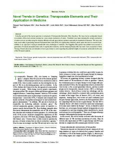
nucleation, which can considerably accelerate the mechanical failure and reduce the fatigue life of structures prone to pitting corrosion [34] (e.g., aircrafts, bridges, and pipelines). Due to the complex evolving morphology of pits, creating conforming FE meshes to simulate the mechanical behavior of the corroded material via the standard FEM can be a challenging task. In contrast, the fully mesh-independent feature of the HIFEM provides an appropriate computational technique for the treatment of this problem. In this example, we demonstrate the application of the higher-order HIFEM for evaluating the stress field in a 20 cm # 5 cm axially loaded steel beam (Est D 200 GPa, #st D 0:36) subjected to pitting corrosion, as shown in Figure 11(a). Simulated stress fields in the corroded beam are illustrated in Figure 11(b) and (c), where a 360 # 90 structured FE mesh is employed to discretize the bounding box of the domain. As shown in the insets of this figure, the HIFEM easily captures stress concentrations in the vicinity of pits intersecting with one another. 5.3. Heterogeneous material mechanical behavior In this final example problem, the HIFEM is employed to simulate the mechanical behavior of a 4:5 (m # 4:5 (m random fiber composite domain (Figure 12(a)) with a copper matrix (Em D 85 GPa, #m D 0:3) and carbon fibers (Ef D 300 GPa, #f D 0:3). The left edge of this heterogeneous domain is constrained against horizontal and vertical displacements, while a uniform distributed load of fN D 30 N/m is applied along its right edge. Figure 12(b) illustrates the HIFEM approximation of the normal stress field in the x direction using a 100 # 100 structured FE mesh. Note that, despite the intricate heterostructure of this composite material, the HIFEM is able to simulate stress concentrations along the interfaces between embedded fibers and the matrix. Copyright © 2015 John Wiley & Sons, Ltd.
Int. J. Numer. Meth. Engng 2016; 105:403–415 DOI: 10.1002/nme
414
S. SOGHRATI AND J. L. BARRERA
Figure 12. Third application problem: (a) microstructure and boundary conditions of a 4:5 (m # 4:5 (m domain of a fiber-reinforced composite with copper matrix and carbon fibers and (b) hierarchical interfaceenriched FEM approximation of the normal stress field in the x direction using a 100 # 100 structured finite element mesh for discretizing the domain.
6. CONCLUSION A new algorithm was introduced for constructing enrichment functions of higher-order Lagrangian elements in the HIFEM. While the focus of this article was on the HIFEM approximation of problems discretized using six-node triangular elements, the proposed approach is general and can be applied to other types of higher-order elements. This recursive algorithm relies on the hierarchical construction of distorted integration (children) elements in nonconforming (parent) elements cut by multiple materials interfaces. The resulting children elements share some of the midpoints of the parent element, which can lead to distortion in such elements. A special mapping was also introduced for evaluating basis functions in distorted children elements, which maintains a constant Jacobian determinant (if element edges are straight) and thus reduces the computational cost and improves the accuracy of the higher-order HIFEM. A convergence study was presented to show that the second-order HIFEM yields a similar precision and convergence rate as those of the standard FEM with conforming FE meshes. We then implemented this method to perform mesh-independent simulations of the thermal response and mechanical behavior of a porous titanium, a beam subjected to pitting corrosion, and a heterogeneous random fiber composite. ACKNOWLEDGEMENTS
This work was supported in part by The Ohio State University Materials Research Seed Grant Program, funded by the Center for Emergent Materials, an NSF-MRSEC, grant DMR-1420451; the Center for Exploration of Novel Complex Materials; and the Institute for Materials Research. The authors acknowledge the allocation of computing time from Ohio Supercomputer Center. J. L. Barrera also acknowledges financial support from Senescyt. REFERENCES 1. Frey P, George PL. Mesh Generation. John Wiley & Sons: London, 2010. 2. Beall M, Walsh J, Shephard M. Accessing cad geometry for mesh generation. In Imr, 2003; 33–42. 3. Reid A, Langer S, Lua R, Coffman V, Haan S, García R. Image-based finite element mesh construction for material microstructures. Computational Materials Science 2008; 43(4):989–999. 4. Cattaneo PM, Dalstra M, Frich LH. A three-dimensional finite element model from computed tomography data: a semi-automated method. Proceedings of the Institution of Mechanical Engineers, Part H: Journal of Engineering in Medicine 2001; 215(2):203–212. 5. Cuillière JC, Francois V, Drouet JM. Automatic mesh generation and transformation for topology optimization methods. Computer-Aided Design December 2013; 45(12):1489–1506. 6. Kannan R, Hendry S, Higham N, Tisseur F. Detecting the causes of ill-conditioning in structural finite element models. Computers & Structures 2014; 133:79–89. 7. Guldberg R, Hollister SJ, Charras GT. The accuracy of digital image-based finite element models. Journal of Biomechanical Engineering 1998; 120(2):289–295. Copyright © 2015 John Wiley & Sons, Ltd.
Int. J. Numer. Meth. Engng 2016; 105:403–415 DOI: 10.1002/nme
HIGHER-ORDER HIERARCHICAL INTERFACE-ENRICHED FINITE ELEMENT METHOD
415
8. Lu Q, Shephard MS, Tendulkar S, Beall MW. Parallel mesh adaptation for high-order finite element methods with curved element geometry. Engineering with Computers 2014; 30(2):271–286. 9. Zhu XY, Chen WQ, Huang ZY, Liu YJ. Fast multipole boundary element analysis of 2D viscoelastic composites with imperfect interfaces. Science China Technological Sciences 2010; 53(8):2160–2171. 10. Liu YJ, Mukherjee S, Nishimura N, Schanz M, Ye W, Sutradhar A, Pan E, Dumont NA, Frangi A, Saez A. Recent advances and emerging applications of the boundary element method. Applied Mechanics Reviews 2011; 64(3):030802-1–030802-38. 11. Wang HT, Yao ZH. Large-scale thermal analysis of fiber composites using a line-inclusion model by the fast boundary element method. Engineering Analysis with Boundary Elements 2013; 37(2):319–326. 12. Belytschko T, Krongauz Y, Organ D, Fleming M, Krysl P. Meshless methods: an overview and recent developments. Computer methods in applied mechanics and engineering 1996; 139(1):3–47. 13. Movahedian B, Boroomand B, Soghrati S. A trefftz method in space and time using exponential basis functions: application to direct and inverse heat conduction problems. Engineering Analysis with Boundary Elements 2013; 37(5):868–883. 14. Rosolen A, Peco C, Arroyo M. An adaptive meshfree method for phase-field models of biomembranes. part I: approximation with maximum-entropy approximants. Journal of Computational Physics 2013; 249:303–319. 15. Soghrati S, Mai W, Liang B, Buchheit RG. A boundary collocation meshfree method for the treatment of Poisson problems with complex morphologies. Journal of Computational Physics 2015; 281:225–236. 16. Zhang L, Gerstenberger A, Wang X, Liu WK. Immersed finite element method. Computer Methods in Applied Mechanics and Engineering 2004; 193(21-22):2051–2067. 17. Wu CT, Guo Y, Askari E. Numerical modeling of composite solids using an immersed meshfree Galerkin method. Composites Part B: Engineering 2013; 45(1):1397–1413. 18. Kumar S, Singh IV, Mishra BK. A multigrid coupled (FE-EFG) approach to simulate fatigue crack growth in heterogeneous materials. Theoretical and Applied Fracture Mechanics 2014; 72(1):121–135. 19. Oden TJ, Duarte CA, Zienkiewicz OC. A new cloud-based hp finite element method. Computer Methods in Applied Mechanics and Engineering 1998; 153(1-2):117–126. 20. Babuska I, Melnek JM. The partition of unity method. International Journal for Numerical Methods in Engineering 1997; 40(4):727–758. 21. Singh IV, Mishra BK, Brahmankar M, Bhasin V, Sharma K, Khan IA. Numerical simulations of 3-d cracks using coupled EFGM and FEM. International Journal for Computational Methods in Engineering Science and Mechanics 2014; 15(3):227–231. 22. Belytschko T, Gracie R, Ventura G. A review of extended/generalized finite element methods for material modeling. Modeling and Simulation in Material Science and Engineering 2009; 17:043001-1–043001-53. 23. Soghrati S, Aragón AM, Duarte CA, Geubelle PH. An interface-enriched generalized finite element method for problems with discontinuous gradient fields. International Journal for Numerical Methods in Engineering 2012; 89(8):991–1008. 24. Soghrati S, Geubelle PH. A 3D interface-enriched generalized finite element method for weakly discontinuous problems with complex internal geometries. Computer Methods in Applied Mechanics and Engineering 2012; 217-220:46–57. 25. Soghrati S, Thakre PR, White SR, Sottos NR, Geubelle PH. Computational modeling and design of actively-cooled microvascular materials. International Journal for Heat and Mass Transfer 2012; 55(19):5309–5321. 26. Soghrati S, Najafi AR, Lin JH, Hughes KM, White SR, Sottos NR, Geubelle PH. Computational analysis of activelycooled 3D woven microvascular composites using a stabilized interface-enriched generalized finite element method. International Journal of Heat and Mass Transfer 2013; 65:153–164. 27. Aragón AM, Soghrati S, Geubelle PH. Effect of in-plane deformation on the cohesive failure of heterogeneous adhesives. Journal of Mechanics and Physics of Solids 2013; 61:1600–1611. 28. Soghrati S. Hierarchical interface-enriched finite element method: an automated technique for mesh-independent simulations. Journal of Computational Physics 2014; 275(1):41–52. 29. Zienkiewicz OC, Taylor RL, Zhu JZ. The Finite Element Method: Its Basis and Fundamentals. Elsevier: Oxford, 2005. 30. Soghrati S, Duarte CA, Geubelle PH. An adaptive interface-enriched generalized finite element method for the treatment of problems with curved interfaces. International Journal for Numerical Methods in Engineering, 102(6): 1352–1370. 31. Lee NS, Bathe KJ. Effects of element distortions on the performance of isoparametric elements. International Journal for Numerical Methods in Engineering 1993; 36(20):3553–3576. 32. Frankel GS. Pitting corrosion of metals. Journal of The Electrochemical Society 1998; 145(6):2186–2198. 33. Scheiner S, Hellmich C. Stable pitting corrosion of stainless steel as diffusion-controlled dissolution process with a sharp moving electrode boundary. Corrosion science 2007; 49(2):319–346. 34. Sankaran KK, Perez R, Jata KV. Effects of pitting corrosion on the fatigue behavior of aluminum alloy 7075-t6: modeling and experimental studies. Materials Science and Engineering: A 2001; 297(1):223–229.
Copyright © 2015 John Wiley & Sons, Ltd.
Int. J. Numer. Meth. Engng 2016; 105:403–415 DOI: 10.1002/nme