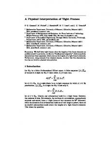
ON THE CONTINUOUS STEERING OF THE SCALE OF TIGHT WAVELET FRAMES ∗
arXiv:1512.02072v1 [cs.CV] 7 Dec 2015
ZSUZSANNA PÜSPÖKI †, JOHN PAUL WARD †, DANIEL SAGE †, AND MICHAEL UNSER † Abstract. In analogy with steerable wavelets, we present a general construction of adaptable tight wavelet frames, with an emphasis on scaling operations. In particular, the derived wavelets can be “dilated” by a procedure comparable to the operation of steering steerable wavelets. The fundamental aspects of the construction are the same: an admissible collection of Fourier multipliers is used to extend a tight wavelet frame, and the “scale” of the wavelets is adapted by scaling the multipliers. As an application, the proposed wavelets can be used to improve the frequency localization. Importantly, the localized frequency bands specified by this construction can be scaled efficiently using matrix multiplication. Key words. Tight wavelet frames, transformability, scalability, Fourier multipliers. AMS subject classifications. MSC2010 42C40
1. Introduction. The representation of objects as the combination of simpler building blocks is fundamental to many applications, including signal and image processing. The advantage of methods that exploit this idea is twofold. First, they often provide a certain measure of locality that allows us to isolate information related to a particular aspect (e.g., frequency or spatial location). Second, an object can be represented in some transform domain with a small number of coefficients; thus, we can compress the representation or summarize the data efficiently by keeping only the most-important coefficients (or a sparse distribution of them). Two somewhat contradictory strategies for generating local representations are: 1) using a generic framework and universal methods (e.g., Fourier analysis or wavelets), or 2) working with specific, signal-adaptive methods (e.g., local principal/independent component analysis). Our interest is in representations that lie between these extremes, where the predefined building blocks can be adapted to the local information by applying a transformation. Thus, we maintain generality and universal performance while capturing specific information. In the context of image processing, local geometric structures are often repeated throughout natural images; however, each occurrence has typically been deformed by an unknown geometric transformation such as a combination of rotation, translation, or scaling. Similar observations can be made for many types of signals, for instance those encountered in bioengineering, seismology, audio, and music processing, to name a few. This motivates us to combine local representations with adaptable transformations. We achieve this goal by looking for transformations within the family of wavelet transforms. A general approach to constructing adaptable wavelets was presented in [16, 18], with the primary focus being steerable wavelets and rotationally invariant properties. The origin of steerable wavelets can be traced back to the work of Freeman and Adelson [4] on steerable filters. Simoncelli et al. extended this work by considering the operations of translation and scaling [12]. As a further generalization, Perona considered arbitrary compact transformations without requiring the group property [8]. Then, in his doctoral dissertation and a series of papers, Teo unified the existing theories and provided a solid ∗ The research leading to these results has received funding from the European Research Council under the European Union’s Seventh Framework Programme (FP7/2007-2013) / ERC grant agreement n◦ 267439. The work was also supported by the Hasler Foundation. † Biomedical Imaging Group, Ecole polytechnique fédérale de Lausanne (EPFL), CH-1015, Lausanne, Switzerland (
[email protected]). Zsuzsanna Püspöki and John Paul Ward have an equal contribution to the paper.
1
2
Z. PÜSPÖKI, J. P. WARD, D. SAGE AND M. UNSER
mathematical framework for the study of transformability based on the theory of Lie groups and Lie algebras [14, 15]. In this paper, we combine transformable filters with primal wavelet systems to form adaptable wavelet frames, focusing on scaling properties. 1.1. Roadmap. In Section 2, we cover notations that will be used throughout the paper and present the mathematical foundations of our wavelet construction. Specifically, we cover transformable filters, with a focus on scaling, and some fundamental wavelet results. According to the terminology introduced by Wilson and Knutsson [19], a collection of transformable filters corresponds to a basis for an equivariant space. Also in Section 2, we define admissible collections of Fourier multipliers (filters) as a special class of transformable families.¡ We ¢ then show how an admissible collection can be used to extend a tight frame of L 2 Rd to a new tight frame. An important point of this construction is that we have some freedom in the choice of the multipliers, which allows us to shape the Fourier transforms of the primal tight frame. The benefit of this construction is that it allows us to extract physical features from a set of data. In Section 2.4, we focus on families of multipliers whose span is invariant to scaling. Then, in Section 2.5, we explain the operation of transforming an extended tight wavelet frame. Essentially, the coefficients corresponding to the extended wavelet frame can be used to compute coefficients for the wavelet frame generated by a scaled version of the multipliers. In Section 3, we present a particular construction that focuses on refining the frequency localization of the primalwavelet system. In Section 4, we consider a two-channel example and illustrate the proposed wavelets. In Section 5, we use our wavelet design to detect circular patters. In Section 6, we evaluate our results and make comparisons with other popular methods. 2. Mathematical Formulation. In this section, we cover the mathematical structure of our wavelet construction. We begin with notations and then introduce general results concerning the extension of a tight frame, before moving on to the details of admissible Fourier multipliers and transformable families. We also discuss how to adapt the extended frame and provide information on the construction of a particular primal-wavelet frame. 2.1. Notation. The variable x represents a point in the spatial domain Rd . A point in the Fourier domain is denoted in Cartesian coordinates as ω . The variables ρ and θ are used to represent ω 6= 0 in polar coordinates, with (2.1)
ρ = |ω |
(2.2)
ω = ρθ.
¡ ¢ The Fourier transform of an L 1 Rd function f is Z (2.3)
fb(ω ) =
Rd
f (x)e−j〈x,ω 〉 dx.
We use the notation log2 to denote the base-two logarithm. 2.2. Operators. The two components of our construction are a primal-wavelet frame and a collection of bounded linear operators on L 2 . Since we are working with a wavelet system, we require these operators to commute with Every operator of this ¡ translations. ¢ d form can be described as a Fourier multiplier in L ∞ R [13, Theorem 3.18]. Specifically, ¡ ¢ for each such operator T , there is a symbol Tb ∈ L ∞ Rd such that (2.4)
© ª F T f = Tb fb,
ON THE CONTINUOUS STEERING OF THE SCALE OF TIGHT WAVELET FRAMES
3
for every f ∈ L 2 (Rd ). A collection of Fourier multipliers is said to be admissible if it satisfies the partition-of-unity property below. D EFINITION 2.1 (cf. [17, Definition 2.1]). A collection of complex-valued functions n max M = {M n }n=1 is admissible if 1. Each M n is Lebesgue-measurable; 2. The squared moduli of the elements of M form the partition of unity nX max
(2.5)
|M n (ω )|2 = 1
n=1
for every ω ∈ Rd \{0}. The partition-of-unity property is important as it allows us to use an admissible collection to extend a tight frame to a new tight frame.© ª ¡ ¢ T HEOREM 2.2 (cf. [17, Theorem 2.4]). Suppose φk k∈Z is a tight frame of L 2 Rd , with f =
(2.6)
X
® f , φk φk
k
and X ¯ ° °2 ®¯ ° f ° = ¯ f , φk ¯2 L2
(2.7)
k
for every f ∈ L 2 (2.8)
¡
¢ n max Rd . Also, let M = {M n }n=1 be admissible. Then, the collection © −1 © ªª bk F Mn φ n=1,...,n max ;k∈Z
is also a tight frame. As in the case of steerable wavelets, we can adapt (or shape) the multipliers while maintaining the tight-frame property if we apply an isometry to the collection. The importance of this construction is prominent in Section 2.4, where we combine a collection of individual trigonometric functions to build trigonometric polynomials. n max P ROPOSITION 2.3. Let {M n }n=1 be an admissible collection and define the vector M 0 to have entries [M]n = M n . If the (n max × n max ) matrix U is an isometry (i.e., U∗ U is the (n max × n max ) identity matrix), then the elements of UM form an admissible collection of 0 . size n max Proof. This follows immediately from the definitions of M and U. 2.3. Admissible Multipliers and Transformable Families. Here, we briefly review the idea of transformability in the context of rotation and then show how it extends to the general setting. In two dimensions, an example of an admissible collection of homogeneous multipliers is M = {M 1 , M 2 }, where (2.9)
M 1 (ω ) = sin(ξ)
(2.10)
M 2 (ω ) = cos(ξ)
and ξ denotes the angle that ω makes with a fixed direction. Any rotation of these functions can be written as a weighted sum of the unrotated functions, as in (2.11)
µ ¶ µ cos(ξ + ξ0 ) cos(ξ0 ) = sin(ξ + ξ0 ) sin(ξ0 )
− sin(ξ0 ) cos(ξ0 )
¶µ
¶ cos(ξ) . sin(ξ)
4
Z. PÜSPÖKI, J. P. WARD, D. SAGE AND M. UNSER
© ª Now suppose that we have a tight frame φk , which is extended by M as described in Theorem 2.2, and let f ∈ L 2 (R2 ). Then the rotated multipliers Mξ0 = {cos(· + ξ0 ), sin(· + ξ0 )}
(2.12)
are also admissible and can be used to extend the frame. Importantly, we can use the frame coefficients from one frame to compute the coefficients for the other by (2.13)
¶ µ µ bk cos(ξ + ξ0 )〉 〈 fb, φ cos(ξ0 ) bk sin(ξ + ξ0 )〉 = sin(ξ0 ) 〈 fb, φ
− sin(ξ0 ) cos(ξ0 )
¶µ
¶ bk cos(ξ)〉 〈 fb, φ bk sin(ξ)〉 . 〈 fb, φ
Steerable wavelets are constructed using a tight wavelet frame {φk }, where the mother wavelet is bandlimited and isotropic. Notice in particular that the rotation invariance of the primal wavelets means that the derived wavelets themselves (not only the multipliers) are rotated by matrix multiplication. This construction has been used to capture the local orientation of features in images [16]. The steerable-wavelet construction is based on the group of rotation operators on L 2 (Rd ); however, an analogous construction can be performed in a more general ¡setting. ¢ D EFINITION 2.4. Let {G a }a∈A be a group of bounded linear operators on L 2 Rd , inn max dexed by a set A. An admissible family of multipliers M = {M n }n=1 is transformable by {G a }a∈A if the span of M is invariant under the action of any operator from {G a }. This definition is a generalization of the idea of eigenfunctions. In the simplest case, we have a single multiplier M = {M } that is an eigenfunction for each transform G a and there exist λa ∈ R such that G a M = λa M .
(2.14) n
max For M = {M n }n=1 containing several functions, this condition is relaxed, as the eigenvalues are replaced by matrices. For any a ∈ A, there must be a matrix Λa such that
G a M1 M1 . .. = Λa .. . . G a M nmax M nmax
(2.15)
When the span of the multipliers is invariant to the action of an operator, the wavelet coefficients of the transformed tight frame can be derived from the wavelet coefficients of the untransformed frame. 2.4. Families of Dilation Multipliers. Here, we are interested in studying scaling properties, so we consider the transformation group {G a }a∈(0,∞) acting on L 2 (Rd ), where G a f = f (a·) for any f ∈ L 2 (Rd ). We restrict our attention to admissible collections of multipliers {M n }, where each multiplier is radial, which means that there exists m n : (0, ∞) → C such that M n (ω ) = m n (|ω |). Therefore, we require (2.16)
span{m n : n = 1, . . . , n max } = span{m n (a·) : n = 1, . . . , n max }
for any dilation a ∈ (0, ∞). Notice that we can write ³ ´ (2.17) m n (·) = m n 2log2 (·) . ¡ ¢ This defines the new function g n := m n 2(·) that should satisfy © ª (2.18) span{g n : n = 1, . . . , n max } = span g n (· + b) : n = 1, . . . , n max
ON THE CONTINUOUS STEERING OF THE SCALE OF TIGHT WAVELET FRAMES
5
for any real b. Hence the span of {g n } should be translation invariant. Conversely, any translation-invariant set gives rise to a dilation-invariant one. This means that, once we identify all shiftable functions, we can easily derive scalable families. Finite-dimensional translation-invariant sets of functions have been classified; the following results follows from [2]. P ROPOSITION 2.5. Let {g 1 , . . . , g nmax } be a family of differentiable functions on R, and let G denote the vector with g n as its nth component. Further, suppose that the collection is shiftable so that, for any b ∈ R, there is a matrix Λ(b) such that G(· + b) = Λ(b)G.
(2.19)
If the components of Λ are differentiable functions, then each g n is a linear combination of functions of the form x k 2αx
(2.20)
for x ∈ R+ \ {0}, k ∈ N, and α ∈ C. P ROPOSITION 2.6. Let {m 1 , . . . , m nmax } be a differentiable collection of functions, and let M denote the vector with m n as its nth component. Further, suppose that the collection is scalable so that, for any a ∈ (0, ∞), there is a matrix Λ(a) that satisfies M(a·) = Λ(a)M(·).
(2.21)
If the components of Λ are differentiable functions, then each m n is a linear combination of functions of the form (2.22)
¡ ¢k ¡ ¢k log2 (x) 2α log2 (x) = log2 (x) x α
for x ∈ R+ \ {0}, k ∈ N, and α ∈ C. Multipliers are required to be bounded to form admissible collections. Therefore, functions of the form (2.22) with k > 0 or with the real part of α non-zero cannot be included. Consequently, we consider admissible collections composed of trigonometric polynomials. A particular example is given by the collection of trigonometric functions © ªnmax M = m n (log2 |·|) n=1 ,
(2.23)
where n max is some fixed degree and where (2.24)
n max {m n }n=1
= {α0 }
½ l[ max l =1
¶ µ ¶¾ 2πl 2πl · , αl sin · , αl cos σ σ µ
Pl max
|αl |2 = 1, and σ > 0. Note that this collection is transformable due to the angleaddition formulas l =0
sin(ρ 1 + ρ 2 ) = sin(ρ 1 ) cos(ρ 2 ) + cos(ρ 1 ) sin(ρ 2 ) (2.25)
cos(ρ 1 + ρ 2 ) = cos(ρ 1 ) cos(ρ 2 ) − sin(ρ 1 ) sin(ρ 2 ).
Admissibility follows immediately from the fact that sin2 + cos2 = 1. A general class of admissible collections of multipliers can be defined by combining trigonometric functions into trigonometric polynomials; a criterion for admissibility
6
Z. PÜSPÖKI, J. P. WARD, D. SAGE AND M. UNSER
is given in [16]. n max P ROPOSITION 2.7. For σ > 0, the collection M = {m(log2 (ρ n |·|))}n=1 , with lX max α0 m(ρ) = p + n max l =1
(2.26)
s
ρ n = 2σn/nmax ,
(2.27)
2 n max
αl cos
and
lX max
µ
¶ 2πl ρ , σ
|αl |2 = 1,
l =0
is admissible if n max ≥ 2l max + 1. Proof. This is a log mapping of Theorem 5.2 from [16]. 2.5. Adapting Extended Frames. The scale-invariance property (2.16) is important because it allows us to scale the multipliers in an admissible collection M using matrix multiplications. When these multipliers are combined with a tight frame to form an extended frame, the scale invariance means that, once we have computed the wavelet coefficients for the system derived from {M n (a·)}, we ©can use matrix multiplications to find ª the coefficients of the wavelet system derived from M n (a 0 ·) for a 6= a 0 . Moreover, we can choose a independently at each point. To see how this works, suppose that we have at our disposal a normalized tight frame {φk }∞ and the scalable, admissible family of dilation multipliers k=1 © ¡ ¢ªnmax n max = m n log2 (|·|) n=1 . {M n }n=1
(2.28)
The collection Ma = {M n (a·)} is also admissible for any a > 0. Indeed, ©
(2.29)
bk } : k ∈ Z, n = 1, . . . , n max F −1 {M n (a·)φ
ª
is a normalized tight frame. Now, let Ma be the matrix whose nth entry is M n (a·). As these collections are scalable, there are matrices Λ(a) such that Ma = Λ(a)M.
(2.30)
Therefore, knowing the frame coefficients of f ∈ L 2 (Rd ) for any frame (2.29) with a > 0, we can easily compute the coefficients for a 0 6= a by (2.31)
bk M 1 (a·)〉 bk M 1 (a 0 ·)〉 〈 fb, φ 〈 fb, φ .. .. = Λ(a 0 )Λ(a −1 ) . . . bk M N (a 0 ·)〉 bk M N (a·)〉 〈 fb, φ 〈 fb, φ
As a particular example, suppose all multipliers are dilations of a single multiplier. Let M be defined as in Proposition 2.7 with n max ≥ 2l max + 1 and σ = 2. In this situation, we have that (2.32)
Ma = UDa B,
where U is the (n max × (2l max + 1)) matrix with entries (2.33)
1 ejπl log2 (ρ n ) [U]n,l = p n max
ON THE CONTINUOUS STEERING OF THE SCALE OF TIGHT WAVELET FRAMES
7
for l = −l max , . . . , l max and n = 1, . . . , n max ; B is the vector with entries ( α|l | p ejπl log2 (ρ) , l 6= 0 2 (2.34) [B]l = α0 , l =0 and Da is the diagonal matrix with entries (2.35)
[Da ]l ,l = ejπl log2 (a) .
The matrix U is an isometry, so for any a 0 > 0, we have that (2.36) (2.37)
Ma 0 = UDa 0 B ¡ ¢ = UDa 0 Da −1 UT Ma
(2.38)
= UDa 0 a −1 UT Ma .
Therefore, Ta,a 0 = UDa 0 a −1 UT is the matrix used to transform Ma into Ma 0 . 2.6. Wavelets. Our construction is initialized with a tight wavelet frame of L 2 (Rd ) whose basis functions are generated by dilations and translations of the single mother wavelet φ. Proposition 2.8 exhibits sufficient conditions for such a wavelet system. P ROPOSITION 2.8. Let h : [0, ∞) → R be a smooth function that satisfies I. h(ρ) = 0 for ρ > π (bandlimited) X ¯ ¡ q ¢¯2 ¯h 2 ρ ¯ = 1 II. q∈Z ¯ dn h ¯¯ III. = 0 for n = 0, . . . , N (vanishing moments). dρ n ¯ρ=0 For 1 ≤ p ≤ ∞, the mother wavelet ψ whose d -dimensional Fourier transform is given by ´ ³ b (ω ) = h kω k` (2.39) φ p generates a normalized tight wavelet frame of L 2 (Rd ) whose basis functions ¡ ¢ (2.40) φq,k (x) = φ x − 2q k ¡ ¢ have vanishing moments up to order N . In particular, any f ∈ L 2 Rd can be represented as X X ® (2.41) f = f , φq,k φq,k . q∈Z k∈Zd
Proof. This follows from a combination of Parseval’s identity for Fourier transforms and Plancherel’s identity for Fourier series. In Section 3, we use Meyer-type wavelets, constructed using the techniques of [17]. We want our final wavelets to take the shape of the multipliers in an admissible family. Therefore, we would ideally like to use a primal wavelet where h is a constant multiple of the characteristic function of [π/4, π]. However, discontinuities in the Fourier domain correspond to slow decay in the spatial domain. Therefore, as a tradeoff, we propose a profile h ² that is a smooth approximation to the characteristic function of [π/4, π], where ² is an approximation parameter. For this construction, we define a smooth, non-decreasing function G that satisfies G(γ) = 0 for γ < −1 and G(γ) = π/2 for γ > 1. Then, for an approximation parameter ², we define ¶ µ ¶ µ γ+1 π γ−1 − +G (2.42) H² (γ) = G ² 2 ²
8
Z. PÜSPÖKI, J. P. WARD, D. SAGE AND M. UNSER
F IG . 3.1. Plot of h ² (ρ) and h ² (ρ/2) for the Meyer wavelet system.
and µ µ µ 1+² ¶¶¶ 2 h ² (γ) = 2−1/2 cos H² log γ . π
(2.43) For
(2.44)
γ < −1 0, ¡ ¢ 3 5 16 35π −1 7 3 G(γ) = 64 7 γ + 5 γ − γ + γ + 35 , −1 ≤ γ < 1 π γ ≥ 1, 2,
the resulting function h ² and a dilated version are plotted in Figure 3.1. 3. Localized Frequency. In this section, we consider the wavelet frame defined by the Meyer-type mother wavelet of Section 2 combined with the multipliers defined in Proposition 2.7. We require the energy of the multipliers to be localized within the support of the wavelets, so that scaling the multipliers will provide a close approximation to scaling the wavelets. 3.1. Detailed Example. Here is an example of the proposed construction. We define b ω ) = h ² (ρ) where h ² is given as in the radial mother wavelet φ in the Fourier domain by φ( (2.42), (2.43), and (2.44). Fourier-domain representations of h ² (ρ) and h ² (ρ/2) are shown in Figure 3.1. We extend this wavelet frame using the admissible collection of Proposition 2.7 with n max = 2l max + 1. The trigonometric polynomial m is defined by the vector (3.1)
α=
p 4685 ¡ 125, 14055
p 101 2,
p 53 2,
p 16 2,
p ¢ 2 2 ,
which is determined by sampling a polynomial B-spline of degree 3. It is shown in Figure 3.2. We note that the choice of the multiplier depends on the application. The one used in this paper corresponds to a wavelet that has good localization in the Fourier domain. For α defined in this way, we see that the collection is admissible by Theorem 2.7, and the extended wavelet frame is tight.
ON THE CONTINUOUS STEERING OF THE SCALE OF TIGHT WAVELET FRAMES
9
¡ ¢ F IG . 3.2. Plot of the Fourier multiplier m log2 (·) on the interval [π/32, 2π].
3.2. Pseudo-Scaling. Our construction allows us to perform pseudo-dilations of the wavelets within the extended tight frame of Section 3.1. To explain this procedure, we define the scaled multipliers (3.2)
© ¡ ¡ ¢¢ªnmax M a := m log2 ρ n |a·| n=1 .
We recall that h ² is the Fourier profile of the primal mother wavelet φ. For a given parameter ¶ µ π 2 (3.3) 0 < ²0 < 1 − 1+² , 2 4 we define the interval (3.4)
(4−1−² π + ²0 , 2(4−1−² π + ²0 )]
within the support [4−1−² π, π] of the profile h ² . Furthermore, note that the 2q dilations of this interval are non-overlapping. Here, we formally define the operation of pseudo-scaling wavelets as scaling of the corresponding multipliers. The pseudo-scaled wavelet system is formed by applying M a to the primal-wavelet system. Within this system, we can very closely approximate true scaling. We consider the multiplier defined in Section 3.1. b 0 attains its maximal value in Let M 0 be an element of M 1 such that the profile of φM the interval (3.4). Let p 0 denote the location of the maximum, and define p(a) = p 0 /a, as −1 b illustrated in Figure 3.3. We define the wavelet ¡ −1 ¢ ψ := F {M 0 φ}. The profile of the dilated b a · , attains a maximum at p(a). The pseudoversion of the Fourier transform of ψ, ψ dilated version of ψ is defined as (3.5)
© ¡ ¢ª b 2q a · , ψa := F −1 M 0 (a·)φ
where q a satisfies (3.6)
¡ ¤ p(a) ∈ 2q a (4−1−² π + ²0 ), 2q a 2(4−1−² π + ²0 ) .
In other words, p(a) belongs to the 2q a dilation of the interval (3.4). The Fourier transform of ψ and a sequence of pseudo-dilations are shown in Figure 3.3. Note in particular the
10
Z. PÜSPÖKI, J. P. WARD, D. SAGE AND M. UNSER
b −1 ·) for a = 1.0 (solid) and a = 1.5 (dotted). The location of the peak is p(a), F IG . 3.3. Left: Profile plot of ψ(a b a , for a = 1, 1.3, 1.5, 1.7. The which is indicated by the dashed vertical line. Right: Profile plot of pseudo-dilations ψ dashed vertical line is located at 2(4−1−² π + ²0 ).
F IG . 3.4. Quality metric %ψ as a function of the dilation a.
transition as p(a) crosses the point 2(4−1−² π + ²0 ). The wavelets maintain their shape due to the overlapping primal windows. We measure the correlation between the truly scaled ψ and its pseudo-dilated counterpart ψa as Ã* (3.7)
%ψ (a) := max
ψ ° a° °ψa °
L2
ψ(a·) ,° ° °ψ°
+
! ,0 .
L2
This is similar to the quality metric defined in [3] to measure the approximation of shiftable wavelets. Values close to one indicate that the pseudo-dilated wavelets provide a close match to true dilation, while smaller values indicate a poor match. We show in Figure 3.4 the evolution of %ψ as a function of dilation. There, we illustrate the quality of pseudoscaling using the empirically defined value ²0 = 0.45. Due to the periodic nature of pseudoscaling, the minimum of %ψ is found by analyzing a single period of the trigonometric function. We compute this minimum to be 0.998.
ON THE CONTINUOUS STEERING OF THE SCALE OF TIGHT WAVELET FRAMES
11
3.3. Comments on the Construction. In Proposition 2.7, the periodicity of the trigonometric functions means that the multipliers are periodic in scale. For example, ¡ ¢ ¡ ¢ (3.8) cos πl log2 (22 ·) = cos πl log2 (·) , since l is an integer. Essentially, our tight-frame construction consists of the application of an admissible b is zero in a neighborhood of the oricollection {M n } to bandlimited wavelets φ, where φ b q ·) segment the domain so that, for gin. Therefore, the supports of the scaled wavelets φ(a q b each scale, the support of φ(a ·) will cover a finite number of scaling periods (of the form [ρ, r ρ]) of the multipliers. The fact that cyclic scaling can be combined naturally with a geometric division of the Fourier domain motivates our interest in cyclically scalable families for use with wavelets. Also note that there should exist synchronization between the cyclic periodicity and the discrete scales of the wavelets, the usefulness being that one could get the rough discrete scale from the wavelet hierarchy, the local scale being refined by adapting the multipliers. Furthermore, we can scale the frame independently at each point, due to the transformability property seen in Proposition 2.6. 4. Special Case: One Complex Multiplier. In the localized-frequency construction, arbitrary localization can be obtained if one is willing to work with a highly redundant wavelet frame. Here, to introduce the ideas, we provide details for the simplified case where the admissible collection contains only two functions: sine and cosine. We propose to use the mother wavelets ψcos and ψsin that are defined by their Fourier domain profiles (4.1)
b cos (ω ) = h(|ω |) cos(ω0 log2 (κ|ω |)) ψ
(4.2)
b sin (x) = h(|ω |) sin(ω0 log2 (κ|ω |)), ψ
which have two parameters: κ and ω0 . The parameter κ specifies a local shift of the cosine and sine under the window h in the frequency domain. The dependence of this frequency shift on κ is cyclic: all values of κ that differ by 2n2π/ω0 produce equivalent frequency shifts. The second parameter is ω0 . It determines the size of these local-frequency cycles as well as the number of oscillations of cosine and sine that fall within the support of h. In practical designs, one can tune these parameters to select the number of oscillations (ω0 ) and the phase shift (κ) of the sinusoids within the support of h. In [10], the authors were using ω0 = 4π and κ = 25 /π. The function h can be defined as 2−1/2 h ² , where h ² is from (2.43). The two real mother wavelets are combined in the single complex wavelet (4.3) (4.4)
ψ(x) = ψcos (x) + jψsin (x) n o = F −1 h(| · |)ejω0 log2 (κ|·|) (x).
The polar form of the analysis coefficients of the complex wavelets ψs,k is (4.5)
® A s,k ejβs,k = f , ψs,k ,
where s ∈ Z denotes the scale and k ∈ Zd the position. We note the following scaling relationship between ψ and ψcos : ³ ´ (4.6) Re ejβ ψ = cos(β)ψcos − sin(β)ψsin n o (4.7) = F −1 h(| · |) cos(ω0 log2 (2β/ω0 κ| · |)) .
12
Z. PÜSPÖKI, J. P. WARD, D. SAGE AND M. UNSER
F IG . 4.1. Reference images (left) and radius estimations (right). The measured spot size as a function of the actual spot size. The straight black curve represents the theoretical values. The light grey curve shows the estimated radius extracted from the phase of the wavelet coefficients in the complex case. The dark grey curve visualizes the estimated radius determined by scaling the multipliers in the multichannel case.
A similar relationship holds between ψ, ψcos , and ψsin upon taking the imaginary part. When analyzing a real-valued function f , we use this property to scale the complex wavelets. We arrive at an expansion of f as a sum of locally scaled versions of ψcos , where ψcos is adapted to the signal at each scale s and position k as in X ® f = f , ψs,k ψs,k (4.8) s,k
(4.9)
=
X³
=
X
=
X
´ A s,k ejβs,k ψs,k
s,k
(4.10)
³ ´ A s,k ejβs,k ψs,k
s,k
(4.11)
n ³ ³ ´´o s A s,k F −1 2sd e−j2 k·ω h(2s | · |) cos ω0 log2 2βs,k /ω0 κ| · | .
s,k
© ª D EFINITION 4.1. Let ψs,k be a wavelet system as defined above. For a function f : Rd → R, let the wavelet coefficients be defined as in (4.5). Then, we define the scale-adapted f wavelets ψs,k by (4.12)
n ¡ ¡ ¢¢o s f ψs,k = F −1 2sd e−j2 k·ω h(2s | · |) cos ω0 log2 κs,k | · |
(4.13)
κs,k = 2βs,k /ω0 κ,
for 0 ≤ βs,k < 2π. Using the scale-adapted wavelets, we view A s,k as the coefficient associated to the analysis of f with a version of ψcos that is optimally scaled locally. Scaling ψs,k by 2(−βs,k )/ω0 creates the best match between f and a locally scaled version of ψcos . An application of the single complex multiplier case was presented in [10]. To compare the estimation properties of the one complex multiplier with the more general multichannel case (with α corresponding to (3.1)), we generated a series of test images. The spots range in size from 8 pixels to 11 pixels with step size 0.2. The reference images (left) and the correspondence between the measured spot radius and the actual spot size is illustrated in Figure 4.1. Since the multichannel case provides a better estimate of size (with a relatively small computational overhead), from now on we focus on that case.
ON THE CONTINUOUS STEERING OF THE SCALE OF TIGHT WAVELET FRAMES
13
5. Spot Detection. We summarize the algorithm for the detection and size estimation of circular patterns that we call spots. We suppose that a scalable wavelet with the proper Fourier multipliers are at our disposal. (1) (Wavelet Analysis With Scalable Wavelets) We decompose the image with the scalable wavelet. At each location k and dyadic scale s, we have n max channels, corresponding to the number of Fourier multipliers. The first n max stage outputs a map of wavelet coefficients {w n (s, k)}n=1 . (2) (Thresholding [Optional] and Non-Maximum Suppression) We assume that the keypoints (center of spots) are sparse in the image. We thus ignore points where the response of the detector is small, by applying global threshold based n max on the `2 norm of the wavelet coefficients {w n (s, k)}n=1 over the channels at each scale and location. We additionally apply local non-maximum suppression to prevent multiple detections of the same object. (3) (Adaptation) We perform the adaptation step (steering of the scale) at each location that was retained by the previous step. The size of an object corresponds to a maxima in the response of the wavelet detector. The wavelets therefore have to be “scaled” to look for the precise scale that elicits the largest response. (4) (Postprocessing [Optional] ) We rank the candidates based on a particular measure (e.g., strength of the response of the wavelet, contrast with respect to the neighboring background, SNR). We choose the best corresponding results. 6. Experimental Results. Our algorithm to detect spots and measure their size has been programmed as a plug-in for the open-source image-processing software ImageJ [1]. To evaluate the performance of the algorithm, we use a variety of test images, including synthetic ones and real micrographs. The aim of our experiments is to measure the speed of our method, its accuracy, and its robustness against background signal. We also want to compare our method to other popular spot-detection methods in the literature. In the evaluation phase we use the Hungarian algorithm to match the detections with the nodes of the original grid. The detections are accepted if they are no further than 5 pixel from the original nodes. Otherwise, they are counted as false positives. To make a quantitative evaluation, we compute the Jacquard index and the root-mean-square error (RMSE) for the estimation of the position and radius. We note that the RMSE is computed for the matched detections only. 6.1. Synthetic Data. There exist several approaches dedicated to the detection of circular objects and measuring their radii. We can separate these approaches into three main categories: classical global methods (e.g., morphology and adaptive thresholding); methods based on the detection and analysis of edges and gradients (e.g., the circular Hough transform [5] and active contours); and approaches based on filtering (e.g., Laplacian of Gaussian (LoG), determinant of Hessian (DoH), and wavelet-based techniques [7]). Global methods are mostly used for the evaluation of clear structures without background signal or noise. Their accuracy drops significantly for complex structures that appear in biological experiments, due to their sensitivity to noise. Edge-based methods are highly demanding in computational time and capacity. Filter-based methods include detectors with parametric templates that correspond to a specific range of sizes or scales. In [11], it was shown that the LoG filter can be likened to a whitened matched filter and offers optimal properties for detection in a broad category of images. In [6], Lindeberg proposed a multiscale extension of the LoG-based detection scheme to overcome the limitation of the single scale. His method uses numerous passes of the LoG filter to
14
Z. PÜSPÖKI, J. P. WARD, D. SAGE AND M. UNSER
F IG . 6.1. Position and radius estimation error (in pixels) in a sense of root mean square error (RMSE) as a function of running time.
capture the location and the size of spots. The computational efficiency of the algorithm highly depends on the diversity of the spot size. For the comparison, we have chosen the following methods: Multiscale Laplacian of Gaussian, circular Hough transform, and thresholding and connected components. 6.1.1. Speed. First, we generate a series of test images (of size (1,000 × 1,000)) where we control the location of the spots and their radius. The ground-truth data contain 200 disks, with radii varying between 8 and 40 pixels. We allow overlap between neighboring spots, by at most 10 pixels. In the case of the multiscale Laplacian of Gaussian and the circular Hough transform, the parameters determine the precision of the algorithm (corresponding to their “search space”). With generous settings they provide better results; however, their computation time increases dramatically. In the case of our method, we control the speed by modifying the global threshold for the wavelet coefficients (Step 2). The RMS errors of the estimation of position and radius as a function of running time are summarized in Figure 6.1. We note that the application area of the method “thresholding and connected components” is limited to noise-free data. Based on the graphs, we conclude that our algorithm performs better for a given computation time than the competing methods. 6.1.2. Robustness Against Background Signal. In fluorescence microscopy, the presence of background signal (autofluorescence) is typical. We test the robustness of our algorithm to this phenomena. To generate our test images, we use the results of Sage et al. [11], who gave an experimental validation on the spectral power density of fluorescencemicroscopy images, claiming that it is isotropic. The corresponding fractional Brownian
ON THE CONTINUOUS STEERING OF THE SCALE OF TIGHT WAVELET FRAMES
15
F IG . 6.2. From left to right and from top to bottom: detections on the test image corrupted with additive isotropic Brownian motion (mean 0, standard deviation 2.0); detections on the test image corrupted with additive isotropic Brownian motion (mean 0, standard deviation 8.0).
F IG . 6.3. Jaccard index under isotropic Brownian motion (background signal), as a function of the standard deviation σ of the noise.
motion (fBm) is described in [9]. Thus, we represent the power density function by kωk−s , where ω is the radial spatial frequency and s is the fractal exponent. As in the previous case, we generate a series of test images (of size (1,000 × 1,000)), where we control the location of the spots and their radii. We intend to detect different spots, with radii varying between 8 and 40. We allow overlap between neighboring spots, by at most 10 pixels. To make the detection more challenging, we add some isotropic back-
16
Z. PÜSPÖKI, J. P. WARD, D. SAGE AND M. UNSER
F IG . 6.4. Position and radius estimation error (in pixels) in a sense of root mean square error (RMSE) under isotropic Brownian motion (background signal), as a function of background standard deviation (σ).
ground signal (fBm), with a mean of zero and a standard deviation ranging from 0 to 10. An illustration of the test images can be seen in Figure 6.2, along with particular results. We set the running time of the corresponding algorithms to the same order of magnitude (favoring the competing ones). The Jaccard index is presented in Figure 6.3, and the RMS errors in Figure 6.4. Based on the graphs, we confirm that our algorithm has a clear advantage in terms of accuracy in the presence of significant background. 6.2. Biological Data. As a final illustration, we present results on two biological micrographs. Figure 6.5 features cells in fluorescence microscopy. The detections and radius measurements are accurate, despite the heavy background signal and the fact that the intensity of the cells are varying. Figure 6.6 visualizes human HT29 colon-cancer cells 1 . Our algorithm works well in this case as well. 7. Conclusion. In this paper, we presented a general construction of adaptable tight wavelet frames, focusing on scaling operations. We applied our wavelet-based framework to detect and estimate the scale of circular structures in images. The attractive features 1 http://www.broadinstitute.org/bbbc/BBBC008/
ON THE CONTINUOUS STEERING OF THE SCALE OF TIGHT WAVELET FRAMES
17
F IG . 6.5. From left to right: cells in fluorescence microscopy; corresponding detections.
F IG . 6.6. From left to right: human colon-cancer cells; corresponding detections.
of our algorithm are (i) our wavelets can be scaled on a quasi continuum without significant computational overhead; (ii) robustness; and (iii), speed. The effectiveness of our approach in practical applications was demonstrated on synthetic and real biological data in the presence and absence of background signal. REFERENCES [1] M. A BRÀMOFF , P. M AGALHÃES , AND S. R AM, Image processing with ImageJ, Biophotonics International, 11 (2004), pp. 36–42. [2] P. M. A NSELONE AND J. KOREVAAR, Translation invariant subspaces of finite dimension, Proceedings of the American Mathematical Society, 15 (1964), pp. 747–752. [3] K. N. C HAUDHURY AND M. U NSER, On the shiftability of dual-tree complex wavelet transforms, IEEE Transactions on Signal Processing, 58 (2010), pp. 221–232. [4] W. T. F REEMAN AND E. H. A DELSON, The design and use of steerable filters, IEEE Transactions on Pattern
18
Z. PÜSPÖKI, J. P. WARD, D. SAGE AND M. UNSER
Analysis and Machine Intelligence, 13 (1991), pp. 891 –906. [5] P. H OUGH, Method and Means for Recognizing Complex Patterns. U.S. Patent 3.069.654, December 1962. [6] T. L INDEBERG, Feature detection with automatic scale selection, International Journal of Computer Vision, 30 (1998), pp. 79–116. [7] J.-C. O LIVO -M ARIN, Extraction of spots in biological images using multiscale products, Pattern Recognition, 35 (2002), pp. 1989 – 1996. [8] P. P ERONA, Deformable kernels for early vision, IEEE Transactions on Pattern Analysis and Machine Intelligence, 17 (1995), pp. 488–499. [9] B. P ESQUET-P OPESCU AND J. V EHEL, Stochastic fractal models for image processing, IEEE Signal Processing Magazine, 19 (2002), pp. 48–62. [10] Z. P ÜSPÖKI , J. WARD, D. S AGE , AND M. U NSER, Fast detection and refined scale estimation using complex isotropic wavelets, in Proceedings of the Twelfth IEEE International Symposium on Biomedical Imaging: From Nano to Macro (ISBI’15), Brooklyn NY, USA, April 16-19, 2015, pp. 512–515. [11] D. S AGE , F. N EUMANN , F. H EDIGER , S. G ASSER , AND M. U NSER, Automatic tracking of individual fluorescence particles: Application to the study of chromosome dynamics, IEEE Transactions on Image Processing, 14 (2005), pp. 1372–1383. [12] E. P. S IMONCELLI , W. T. F REEMAN , E. H. A DELSON , AND D. J. H EEGER, Shiftable multiscale transforms, IEEE Transactions on Information Theory, 38 (1992), pp. 587 –607. [13] E. M. S TEIN AND G. W EISS, Introduction to Fourier analysis on Euclidean spaces, vol. 32 of Princeton Mathematical Series, Princeton University Press, Princeton, N.J., 1971. [14] P. C. T EO AND Y. H EL -O R, Lie generators for computing steerable functions, Pattern Recognition Letters, 19 (1998), pp. 7–17. [15] P. C. T EO AND Y. H EL -O R, Design of multiparameter steerable functions using cascade basis reduction, IEEE Transactions on Pattern Analysis and Machine Intelligence, 21 (1999), pp. 552–556. [16] M. U NSER AND N. C HENOUARD, A unifying parametric framework for 2D steerable wavelet transforms, SIAM Journal on Imaging Sciences, 6 (2013), pp. 102–135. [17] J. P. WARD, K. N. C HAUDHURY, AND M. U NSER, Decay properties of Riesz transforms and steerable wavelets, SIAM Journal on Imaging Sciences, 6 (2013), pp. 984–998. [18] J. P. WARD AND M. U NSER, Harmonic singular integrals and steerable wavelets in L 2 (Rd ), Applied and Computational Harmonic Analysis, 36 (2014), pp. 183–197. [19] R. W ILSON AND H. K NUTSSON, Uncertainty and inference in the visual system, IEEE Transactions on Systems, Man and Cybernetics, 18 (1988), pp. 305–312.