USM Files . ...... functionality and scope of the repository is assumed throughout the ...... Figure 30 shows the object model for the process component repository.
OPEN PROCESS COMPONENTS by Kevin A. Gary
A Dissertation Presented in Partial Fulfillment of the Requirements for the Degree Doctor of Philosophy
ARIZONA STATE UNIVERSITY May 1999
OPEN PROCESS COMPONENTS by Kevin A. Gary
has been approved January 1999
APPROVED: Chair
Supervisory Committee
ACCEPTED:
Department Chair
Dean, Graduate College
ABSTRACT Automated process support is the application of computer technology to assist and automate work on behalf of users. This research considers the application of automated process support in two domains, automated workflow and software process support. Common challenges face these domains. Current automated process support systems are closed in the sense there is little potential for interoperability and reuse between heterogeneous process tools. Additional requirements for handling dynamic and distributed processes also push the limits of current process technology. This research proposes a component-based framework, the Open Process Components framework, for supporting process activities: building process models, executing process models, analyzing them, and evolving them. Processes are envisioned as a set of dynamic, distributed components that interact in meaningful ways. Process components encapsulate heterogeneous implementations behind well-defined interfaces. Open Process Components is derived from common abstractions held in the process literature. These abstractions are mapped to a meta-model of the process space. From this meta-model, software abstractions are derived which form the basis of the framework. The framework is extendable to accommodate representationspecific process information while at the same time conforming to a component contract for interaction. This dissertation presents a conceptual model a component-based process support framework, describes its realization in software, shows how a commercial process tool is integrated into the component environment, and demonstrates component-based process support on two well-known examples in the process literature.
iii
ACKNOWLEDGEMENTS
iv
TABLE OF CONTENTS The Open Process Components Vision 12 1.1
The Open Process Components Vision..................................................................12
1.2
Motivating Scenario...............................................................................................14
1.3
Research Scope ......................................................................................................16
Background 18 2.1
Process Technology Adoption ...............................................................................18 2.1.1 2.1.2 2.1.3
Expected Benefits of Process Technology Adoption.........................................................18 Pitfalls of Process Technology Adoption...........................................................................20 The Process Life Cycle ......................................................................................................21
2.2
Issues in Process Technology.................................................................................22
2.3
Automated Workflow and Software Process .........................................................26 2.3.1 2.3.2 2.3.3
2.4
Techniques for Interoperability and Reuse ............................................................32 2.4.1 2.4.2 2.4.3 2.4.4
2.5
Automated Workflow.........................................................................................................27 Software Process Support ..................................................................................................29 Comparing Automated Workflow and Software Process Support ....................................31
Common Theoretical Foundations.....................................................................................32 Common Translation Languages .......................................................................................36 Interoperability between Multiple Process Support Environments ...................................44 Process Components ..........................................................................................................54
Summary ................................................................................................................58
A Conceptual Framework for Component-based Process Support 60 3.1
Component-based Process Modeling.....................................................................60 3.1.1 3.1.2 3.1.3
3.2
OPC Foundations ...................................................................................................65 3.2.1 3.2.2 3.2.3
3.3
Process Components ..........................................................................................................60 Component-based Process Models ....................................................................................62 Component-based Process Enactment ...............................................................................63
Process Component Meta-model .......................................................................................66 Composing Process Components to Produce Process Models ..........................................75 Process Component Architecture.......................................................................................77
Summary ................................................................................................................82
The Open Process Components Framework 84 4.1
OPC Framework Layer ..........................................................................................84 4.1.1 4.1.2 4.1.3 4.1.4
Process Schema..................................................................................................................85 Process Variables ...............................................................................................................86 Process Types and Substitution Strategy ...........................................................................88 Process State ......................................................................................................................89
4.2
Process Creation, Description, and Elaboration ....................................................91 4.2.1 4.2.2 4.2.3 4.2.4
4.3
Process Component Architecture...........................................................................96 4.3.1 4.3.2 4.3.3
4.4
Component Repository ......................................................................................................97 Component Containers ......................................................................................................99 Event Service ...................................................................................................................100
Example ...............................................................................................................101 4.4.1 4.4.2
4.5
Process Component Creation.............................................................................................91 Process Component Meta-Data .........................................................................................92 Enactable and Non-enactable Process Components ..........................................................94 Process Component History...............................................................................................96
Example Component Meta-models .................................................................................102 Example Component Interactions....................................................................................106
Summary ..............................................................................................................112
Extending the OPC Framework 114 5.1
Extending the Framework Layer .........................................................................114 5.1.1 5.1.2 5.1.3 5.1.4 5.1.5
5.2
The Representation Layer ....................................................................................119 5.2.1 5.2.2
5.3
Process Schema................................................................................................................115 Process States and Transitions .........................................................................................116 Meta-views.......................................................................................................................117 Process Types...................................................................................................................118 Process Implementations .................................................................................................118
Native Representation Layer Extensions.........................................................................119 Wrapped Process Tools....................................................................................................129
Summary ..............................................................................................................139
Sample Processes 142 6.1
The Personal Software Process............................................................................142 6.1.1 6.1.2 6.1.3 6.1.4
6.2
ISPW6 Software Process Example ......................................................................152 6.2.1 6.2.2
6.3
An Introduction to the PSP ..............................................................................................142 The PSP Software Process Script ....................................................................................143 Automating the PSP.........................................................................................................145 PSP Summary ..................................................................................................................151
Description of the ISPW-6 Example ...............................................................................152 Automating the ISPW-6 Example ...................................................................................153
OPC Process Examples Summary .......................................................................161
Conclusions and Future Work 162 7.1
A Review of OPC ................................................................................................162 7.1.1 7.1.2 7.1.3
From Process Space to Software Design .........................................................................162 A Review of Issues in Process Technology .....................................................................164 OPC Benefits ...................................................................................................................167
7.2
Future Work .........................................................................................................169
7.3
Summary ..............................................................................................................171 References............................................................................................................174
Appendix A. OPC Toolset 186 1.1
Starting the Tool...................................................................................................186
1.2
OPC Software Architecture .................................................................................186
1.3
OPC Tool .............................................................................................................190 1.3.1 1.3.2 1.3.3
Main GUI Window ..........................................................................................................191 Creating Processes ...........................................................................................................193 Interacting with Process Components..............................................................................194
Appendix B. Process Weaver Wrapper 200 B.1
Process Weaver ....................................................................................................200 B.1.1 B.1.2
B.2
Process Weaver Architecture ...........................................................................................200 USM Files ........................................................................................................................202
OPC Wrapping of Process Weaver ......................................................................204 B.2.1 B.2.2 B.2.3
Wrapper Architecture.......................................................................................................204 Universal Storage Mechanism Files ................................................................................206 Component Implementations Using the Process Weaver Wrapper .................................207
LIST OF TABLES TABLE 1. TABLE 2. TABLE 3.
Meta-roles, Meta-views, and Environments ..............................................79 Process Implementations and Types for Example ...................................105 Process Weaver work context GUI widget mapping ...............................211
LIST OF FIGURES FIGURE 1. FIGURE 2. FIGURE 3. FIGURE 4. FIGURE 5. FIGURE 6. FIGURE 7. FIGURE 8. FIGURE 9. FIGURE 10. FIGURE 11. FIGURE 12. FIGURE 13. FIGURE 14. FIGURE 15. FIGURE 16. FIGURE 17. FIGURE 18. FIGURE 19. FIGURE 20. FIGURE 21. FIGURE 22. FIGURE 23. FIGURE 24. FIGURE 25. FIGURE 26. FIGURE 27. FIGURE 28. FIGURE 29. FIGURE 30. FIGURE 31. FIGURE 32. FIGURE 33. FIGURE 34. FIGURE 35. FIGURE 36. FIGURE 37. FIGURE 38.
Process spaces............................................................................................15 Process lifecycles .......................................................................................22 WfMC Reference Model (from [123]) ......................................................29 PCIS LCPS Model (from [82]) ..................................................................35 Process Language Translation (from [124]) ..............................................37 WfMC WAPI 1Meta-model (from [124])..................................................39 PIF Schema (from [70]) .............................................................................41 Chained processes (from [127]).................................................................45 Nested subprocesses (from [127]) .............................................................46 PCIS2 Process Object Model (from [93])..................................................50 PCIS2 Architecture Pattern (from [93]).....................................................51 PCIS2 Common Concepts Pattern instantiated for Process (from [93]) ...52 A process component.................................................................................61 A Process Component Tree........................................................................62 Components and Contexts .........................................................................64 Process schema ..........................................................................................66 Default state transition graph for process components ..............................69 Object types and Process types for process components...........................71 3-layer structure of the Open Process Components framework ................74 Top-down vs. bottom-up process trees ......................................................76 OPC process component architecture ........................................................80 Process schema object model ....................................................................85 Process Variables .......................................................................................87 ProcessType and SubstitutionStrategy.......................................................89 ProcessFSM ...............................................................................................90 Process Factories........................................................................................92 Process Component Meta-Data .................................................................93 Process Component Hierarchy...................................................................95 Process Component History.......................................................................96 Process Component Repository .................................................................97 OPC Tools and Environments....................................................................99 OPC Event Service ..................................................................................101 Example Process Tree..............................................................................101 Process Schema for Unit Test ..................................................................102 Process Schema for Unit Testing .............................................................103 Process Schema for Integration Test........................................................103 Process Schema for Test ..........................................................................104 Example Process Type Hierarchy ............................................................105
FIGURE 39. FIGURE 40. FIGURE 41. FIGURE 42. FIGURE 43. FIGURE 44. FIGURE 45. FIGURE 46. FIGURE 47. FIGURE 48. FIGURE 49. FIGURE 50. FIGURE 51. FIGURE 52. FIGURE 53. FIGURE 54. FIGURE 55. FIGURE 56. FIGURE 56. FIGURE 57. FIGURE 58. FIGURE 59. FIGURE 60. FIGURE 61. FIGURE 62. FIGURE 63. FIGURE 64. FIGURE 65. FIGURE 66. FIGURE 67. FIGURE 68. FIGURE 69. FIGURE 70. FIGURE 71. FIGURE 72. FIGURE 73. FIGURE 74. FIGURE 75. FIGURE 76.
Process tree construction .........................................................................107 Starting a process .....................................................................................108 Performing a Process ...............................................................................109 Completing the Process ........................................................................... 111 Process schema extensions ......................................................................115 State transition graph for non-enactable process components.................121 Process schema for ordered processes .....................................................122 Object model extensions for ordered processes.......................................123 Process schema for ECA processes .........................................................125 Object model extensions for ECA processes ...........................................126 Default state transition graph for ECA process components ...................127 A Process Weaver cooperative procedure................................................131 Work context actions and conditions .......................................................133 Process Weaver process schema ..............................................................134 State transition graph for Process Weaver process components ..............135 Process Weaver schema and state transition graph object model ............137 Process Weaver meta-views object model ...............................................138 PSP process script (paraphrased from [53]) ............................................144 PSP process tree.......................................................................................146 PSP factories ............................................................................................148 PSP process tree in OPC..........................................................................149 Specialized performer tool for Test Application......................................151 ISPW-6 software process components ....................................................154 Cooperative procedure for Modify Design process .................................155 Review Design work context ...................................................................155 Test Unit cooperative procedure ..............................................................156 Test Unit work context.............................................................................157 Create Process dialog for ISPW-6 example.............................................158 ISPW-6 example in OPC .........................................................................159 OPC snapshot of Test Unit cooperative procedure instance and work context 160 OPC evolution..........................................................................................163 OPC Java package structure ....................................................................188 Representation Layer Java package structure ..........................................190 OPC main window...................................................................................191 Create process dialog ...............................................................................193 Take control dialog ..................................................................................195 Default performer tool .............................................................................196 Product Open/Close dialog ......................................................................198 Process Weaver architecture ....................................................................201
FIGURE 77. FIGURE 78. FIGURE 79. FIGURE 80. FIGURE 81. FIGURE 82.
Process Weaver USM-formatted file .......................................................203 OPC Process Weaver wrapper architecture .............................................205 Process Weaver RMI service object model .............................................205 Process Weaver component factory interactions .....................................208 PWObserverTool screen snapshot ...........................................................209 PWPerformerTool screen snapshot..........................................................210
CHAPTER 1
The Open Process Components Vision
Automated process support is the application of computer technology to assist and automate work on behalf of users. This research proposes a component-based infrastructure for supporting process activities: building process models, executing process models, analyzing them, and evolving them. The proposed infrastructure does not solve all of these problems in and of itself, but instead provides a platform by which automated process support issues may be addressed in further depth.
This chapter defines the context of this research. This research is part of a larger vision of how processes are constructed, executed, monitored, and analyzed. This is just the first step, providing an infrastructure for realizing this vision by considering trends in software engineering that will effect process technology in the foreseeable future. This chapter places the current research in the context of this vision. The reader is asked to keep in mind that not all of what is discussed in this chapter has been realized; the last section of this chapter presents the scope of this work with respect to this vision.
1.1 The Open Process Components Vision The recent boom of technologies such as the Internet, Java, Visual Basic, and CORBA has given rise to new buzzphrases like “reusable software component”, “distributed object middleware”, “n-tier architecture”, and “ubiquitous client”. The implications (once you get past the hype) these technologies hold for the future of software development and deployment includes “plug and play” software, “rent per use” software and “open marketplaces for distributed components”[27][88][112]. Current approaches to automated process support do not lend themselves to these trends. Automated process support systems are large, monolithic creatures that often require extensive knowledge of the users, tools, and data types in their environment. The systems are usually tied to some underlying representation of process, and in that representation exist dependencies that make componentization of the process models themselves difficult. The research community has begun to recognize and propose solutions to these problems, as is discussed in more detail in Chapter 2. It is suffi-
13
cient to state for now that current automated process support systems are not the open systems that characterize prevailing trends in software development.
Open Process Components (OPC1) is a first step toward realizing a component-based environment for automated process support. It is an exercise in modularization and object-orientation applied in the extreme to automated process support. OPC modularizes process models in order to define boundaries between process fragments. It enumerates objects for infomation in the process domain in order to encapsulate entities in the process space. It “componentizes” processes by capturing collections of objects that act together as a cohesive entity, and interact with other such collections in well-defined ways. By componentizing process, the environment in which the process acts is shielded from the complexity of process representations. Dependencies between processes are not eliminated, but moved to the boundaries between components where they are easily recognized and managed. In a component-based environment, there is hope ideas such as “plug and play processes”, “rent per use processes”, and “open marketplaces for process components” can be realized. The Open Process Components vision is of an environment of distributed process components, where components can be located, adapted, and optimized on demand with respect to a set of process requirements.
Research in providing distributed, interoperable process support focuses on (1) describing low-level infrastructure support for distribution, such as distributed architectures[10][78][110][117] and distributed transactions[10], or (2) distributed process control integration protocols[10][93][110][127], or (3) distributed process data interchange protocols, usually in the form of a common language for translation[70][124]. In the context of current research, OPC contributes new ways of performing control and data integration through component-based design. The OPC approach is to support top-down process decomposition and bottom up synthesis via interacting components. Control integration is achieved by viewing a process model as a collection of interacting components. Data dependencies are reduced by encapsulating components behind well-defined interfaces, eliminating the need for translating between process languages.
1. Open Process Components is referred to by the acronym OPC for the remainder of this document.
14
OPC represents a fundamental departure from traditional approaches in distributed, interoperable process support. OPC promotes a fundamental shift from monolithic process-centered environments to flexible process-enabled environments. OPC is centered around the building blocks of enactable processes: work, people, and artifacts. Participants use their own tool sets and services to do the work. Process participants accept work items in the form of components, manipulate these components, and pass them along to the next participant or activate subsequent components. Strict adherence to prescriptive process definitions and tight integration of tools is not required. From the user’s perspective, work items, or process components, are received from any number of sources and integrated into the user’s personal work space.
1.2 Motivating Scenario Process support has traditionally focused on an organizational perspective[2][43][111][130]. The organization defines its processes from the top-down, starting with strategic goals and attempting to map them down to tactical objectives. Rarely is the existence of multiple process spaces acknowledged[2][131][100][120]. Figure 1 shows the overlapping of process spaces in a hypothetical environment.
15
Organization: MicroSquash
Organization: NetLand Project: WebSurf 98
Project Data
Create Software Product
Process Artifacts
Software Design Project Plans
Reuse Library
Maintain Software
Implement
Design Patterns
Sue's Processes
Test
Metrics
Design Software Bob's Processes
PSP Write Code
Write Test Plan
Test Module Joe's Processes
Jill's Processes
Write Code
Test System
Legend: Process Component
FIGURE 1.
Process Participant
Data Store
Process spaces
Figure 1 shows three types of process spaces (outlined in bold): organizational, project, and personal. The organizational space defines the set of processes and data of an organization. The project space defines the set of process instances and data tailored for a specific project. The personal space defines an individual user’s process space, how she/he goes about performing work. Note that personal and project spaces are not strictly contained in an organizational space. Project “WebSurf 98” is a collaborative project between MicroSquash and NetLand. It employs processes from both organizations, as well as processes from individuals (subcontractors) outside the organization. While this scenario is hypothetical, it depicts the relationship between process spaces in a realistic way.
16
Traditional approaches to process technology adoption focus on the organizational perspective, and to some extent the project perspective (largely in the software process domain). OPC’s motivation is to support an open view of process spaces, where components defined in different spaces come together dynamically to accomplish a given set of process requirements. This requires an understanding of how to express process requirements which does not currently exist in the process community[90], and the existence of an infrastructure that provides advanced process capabilities for supporting multiple spaces. These advanced process capabilities include support for componentization, interoperability, reuse, process brokering, and optimization. OPC is the first step toward such an infrastructure, addressing componentization, interoperability, and reuse. OPC advocates exposing process information in each space as sets of process components. These process components may be dynamically composed across spaces with the help of brokers and intelligent schedulers. Component-supporting architectures would provide distribution and scaleability. This research addresses componentization of process, a first step toward achieving this vision. Research on process component brokering is already under way[101].
1.3 Research Scope Component-based process support is a new technique for addressing requirements facing automated process support systems. OPC provides an infrastructure for applying component-based technology to automated process support. With this infrastructure, many relevant issues in automated process research can be reassessed with respect to component-based computing. An overview of these issues is provided in Chapter 2.
The domain of application of OPC is automated workflow. Automated workflow is the study of modeling and enacting business processes by human and computer agents. Automated software process is a special subset of automated workflow. Automated software processes are considered in substantial depth in this research since the complexity of this domain pushes the limits of today’s workflow technology along several dimensions. The relationship between workflow and automated software process is discussed in detail in Chapter 2.
17
The goal of this research is to specify a framework for component-based process support. The expected benefits of having this framework are: 1.
Interoperability between heterogeneous process representations.
2.
Systematic reuse of process fragments.
3.
Support for dynamic processes.
4.
An open environment for process integration and interoperability.
5.
Extensibility for incorporating new process representations.
6.
Ability to leverage new technologies such as CORBA and Java for process support.
This research has resulted in the development of the OPC framework. The following accomplishments have resulted from this work: 1.
The OPC framework has been specified using common abstractions from the process literature.
2.
Heterogeneous process representations have been integrated into the framework.
3.
An architecture for component-based process support has been designed as a corollary to the framework.
4.
The framework and architecture have been implemented in Java.
5.
Sample processes are demonstrated using the Java implementation.
The contributions of this work to the research community as a whole include: 1.
Validates a component-based approach to process as a useful means of developing open and distributed process systems.
2.
Serves as an attempt at grounding many foundational concepts that have emerged from the maturing field of automated process support.
3.
Provides a fundamentally new approach to process interoperability.
4.
Provides a basis for additional research on process reuse, process brokering, and process optimization.
The remainder of this document is presented as follows. Chapter 2 discusses issues in automated process support technology and how this research addresses these issues. Chapter 3 provides a conceptual overview of the OPC framework, followed by a specification of these concepts in Chapter 4. Chapter 5 discusses how the framework is extended to integrate heterogeneous process representations. Chapter 6 demonstrates OPC on examples found in the literature. An analysis of the OPC approach is given in Chapter 7 with conclusions regarding the viability of this approach.
CHAPTER 2
Background
This chapter is a review of current issues in automated process support technology. It starts with a broad survey on process technology adoption, its benefits and pitfalls, the context in which it is applied, and the ways in which process models are used. The discussion then narrows to recent technical issues in automated process support, and motivates the need to address interoperability and reuse. A brief introduction to automated workflow and automated software process support is given in order to place these issues in the context in which this research addresses them. Specific approaches to interoperability and reuse are then discussed at length. The chapter concludes with a summary of the important issues this research addresses.
2.1 Process Technology Adoption Process is a generic term. Researchers[23][46][89][105] have noted the similarity of information-based processes to manufacturing processes. The hope for both is that computer support will lead to better productivity, quality, and manageability of product development processes. Adopting process technology is more than a “how-to” solution for implementing a process solution in some environment. There are many motivating factors involved, leading to expectations about what impact process technology has on an organization. Likewise, many pitfalls can be encountered, leading to issues that should not be overlooked by those considering process solutions. This section considers the expected benefits, practical pitfalls, and strategic context of adopting process technology.
2.1.1 Expected Benefits of Process Technology Adoption Process is a popular buzzword today. An organization assumes that if it has good processes, good results will follow. As Conradi et.al. points out, “ ...the quality of products and services intrinsically depends on the quality of the associated process...” ([29], p. 4). Why is this assumption made? The application of process support technology is supposed to result in increased productivity and increased quality.
19
Productivity is a prime motivator for workflow technology adoption, as seen by the market domination of production-oriented workflow systems[67]. Production workflow systems are applied to highly repetitive, static processes[46], with organizations obtaining incremental productivity and cost benefits over repeated executions of the process. Automated workflow is increasingly applied to human-oriented processes[29][46], where “human throughput” is emphasized over incremental cost savings. In these types of processes, automated workflow boosts productivity by reducing process cycle time[67]. Automated workflow leads to gains in quality, particularly in human-oriented processes. Workflow systems coordinate tasks and information flow, resulting in better communication, and therefore better quality[46][67].
Christie et. al.[25] identifies five drivers for adopting process automation in software engineering1: 1.
Cost reduction - Automation could reduce staffing, leading to reduced labor costs.
2.
Quality improvement - Christie states in a separate paper, “A project that does not have a clear understanding of the process through which it develops its software is likely to produce an inferior product” ([23], p.3).
3.
Maintaining process capability - Interestingly, organizations with high turnover realize a loss in process knowledge when individuals leave. Explicitly defining processes provides persistence and stability.
4.
Training - Process environments can offer guidance to new individuals in the organization.
5.
Project management support - Managers have greater control and visibility into process performance.
Automated software processes reduce labor costs if the processes are defined and repeatable. However, software processes are not the highly-repetitive, static processes commonly found in workflow, but are highly dynamic, less repetitive, creative processes with a high degree of coordination[33]. These factors reduce the expectation for incremental cost savings gained from high volume production workflows. Instead, productivity gains come from enhanced communication, traceability, and management in coordinated processes.
The emphasis on quality derives from an increased emphasis on process maturity, as defined by the Capability Maturity Model (CMM) from the Software Engineering Institute (SEI)[92]. Emphasis has shifted from product-centered software engineering to process-centered software engineering. Automated process sup-
1. Christie et. al.[25] is a final report on a software process deployment survey first reported in [24]. The same text appears through the first few sections of both reports. [25] is referenced here to avoid ambiguity.
20
port is seen as one way to promote process maturity, by supporting definition, execution, monitoring, simulation, and analysis activities. Drivers 3-5 are benefits derived from explicit process representations serving as a vehicle for communication and understanding. An organization that understands its processes and explicitly defines them is able to preserve process knowledge in the face of high turnover rates. The same representations educate new engineers on how software development is carried out in the organization. Process representations communicate to managers, or team members, current progress and deviations from the planned process. The relationships between the CMM and automated software process support, and the expected benefits of automated software process support, are examined in Section 2.3.2. The relationship between automated workflow and automated software process support is discussed in Section 2.3.
2.1.2 Pitfalls of Process Technology Adoption One cannot discuss the benefits of introducing a new technology without also discussing the pitfalls. Christie et. al.[25] not only identifies expected benefits, but also lists seven potential inhibitors: 1.
Reluctance to use someone else’s technology - A version of the “not invented here” syndrome.
2.
Lack of acceptance of external consultants - A variant on the “not invented here” syndrome. People are reluctant to accept recommendations coming from outside the organization.
3.
Resistance from “old hands” - The introduction of explicit process representations can be seen as an intrusion into well-known processes.
4.
Fears of first-line supervisors - These people have the most to lose from process technology adoption, fearing loss of job or importance if automated processes are adopted. Ironically, it is noted that these are the people who can make the most effective contributions to developing process models.
5.
Disjoint between predicted and actual times for implementation - Process automation learning curves and technical integration problems are cited as common reasons for delays.
6.
Inability to achieve consensus on process definitions.
7.
Inability to predict return on investment.
Kobielus[67] concurs on some of these issues and offers some additional insights into human factors why process technology adoption is difficult in workflow environments. Kobielus concurs that fear of job loss is an important factor, as the introduction of workflow technology is associated with business process reengineering, which is itself often associated with downsizing. Kobielus also notes the following factors: 1.
The “Big Brother” problem - Workers do not want to feel like management is looking over their shoulder as they do their work.
21
2.
Loss of flexibility - Workflows, especially production workflows, are rigid and often fail to capture the flexible and dynamic manner in which people resolve problems in process flow.
3.
Loss of control - Workers do not like to feel as if their work is regulated and controlled by a computer. Loss of control also applies to middle managers who feel their authority is being compromised.
4.
Fear of technology - Unlike software development organizations, non-technical organizations can experience inhibitions due to techno-phobia.
5.
Email clutter - Some users of messaging-based workflow systems feel a rush of power, and tend to send volumes of meaningless emails with false priorities. This can include managers who route all correspondence to everyone below them, when such correspondence is meaningful to only a fraction of people.
These inhibitors or pitfalls to adoption are largely due to human factors issues. Process adoption is often a dead issue before the technology is ever fully deployed. Gaining management and user acceptance are the most important hurdles to overcome. Christie et. al.[25] notes first-line managers may have the most to lose from process technology adoption, and so it is difficult to obtain their buy-in. [25] also notes that up-front costs discourage upper management. Gaining user and management buy-in is so important that Kobielus[67] devotes an entire chapter to the topic, providing detailed recommendations on how a process technology sponsor can win over various people in the organization.
2.1.3 The Process Life Cycle Automating a poor process will not result in a better process[96]. Process definition and enactment are not activities to be done in isolation, but as part of a higher level comprehensive process for achieving better productivity and quality. The application of process support technology must be considered in the context of a larger strategic approach to process adoption within an organization1. In the workflow community, these activities are part of business process reengineering activities, while in software engineering these activities are part of software process engineering, or more specifically, the software process life cycle.
A process life cycle places process modeling and enactment in the context of a holistic approach to process adoption. A process life cycle model considers activities such as requirements analysis, simulation, evaluation, metrics collection, and improvement in addition to modeling and enactment. Several researchers[11][63][72][102] discuss process life cycle activities. Process life cycles focus on management of 1. Or whatever process space process support is applied to. See Chapter 1.
22
automated processes so that continual process improvement takes place. As shown in Figure 2, this usually involves higher level management and analysis activities embedded in a feedback loop. Good automated process support environments help support the process life cycle by allowing for easier translation of process requirements to enactable process representations on the front end, and by providing audit data on the back end. Some tools even support prototyping and simulation for assisting analysis activities.
Any new process modeling and enactment technique must consider its impact on the process life cycle. The technique, even if technically superior, is ultimately inferior if it prohibits continuous process improvement activities. Process models will quickly become stagnant and outdated, rendering the investment in the technology fruitless.
2.2 Issues in Process Technology It is a credit to Osterweil’s seminal 1987 paper[89] that he identified several issues that automated process support technology may address that are still highly relevant in today’s research. The process community has debated these issues and added some new issues as the field has matured. It is not my intent to rehash all of these issues here, as doing so would simply be redundant. The following summarizes issues relevant to OPC that remain of critical importance in the process community.
automated process support
audit data
process modeling
process analysis process requirements & high level models
process improvement recommendations FIGURE 2.
Process lifecycles
prototyping, simulations, walk-throughs
23
• Process Languages A current issue in process automation addresses the suitability of various process languages for different process requirements[31][33][109]. The requirements are derived from the need for understanding, communication, management, analysis, and other uses of process models. Much of the research of the past decade (particularly in software process) has been devoted to developing process representations. A current debate in the research community is whether one language is sufficient for constructing process models, or multiple languages are needed, or one core language with extensions is required[31][109]. OPC provides a new, extendable approach to process support in which different views of components address different requirements for process models.
• Process Granularity Process granularity is the level of detail expressed in a process model. The more detail, the finer the granularity, and the more potential for automated support of the process. There are trade-offs however, as more detailed process models result in complex representations that can be difficult to understand and do not properly communicate intent to participants[33]. Therefore, the level at which a process is to be defined depends on the intended use of the model[33][109]. OPC allows components to be defined at any level of granularity. Components are often composed of other components in aggregation relationships, managing complexity through multiple levels of granularity.
• Dynamic Process Modification One issue that has long separated the workflow and software process communities is the ability to handle dynamic process modification. This refers to the ability to change process models on the fly as processes are enacted. The software process community has recognized this as an important problem from the beginning, given the highly creative and non-prescriptive activities undertaken in real-world software production processes. Several software process systems, such as PEACE[4] and Endeavors[13], address dynamic process modification. Workflow, on the other hand, has enjoyed most of its success in the area of production workflows, which are rigidly defined processes that are not expected to change during
24
enactment. Groupware and email based workflow systems that support ad hoc workflows claim to handle dynamicity, but in reality the types of processes supported lack any significant structure whatsoever, and so it is hard to claim they manage dynamic changes to processes. However, addressing dynamic processes is gaining importance in the workflow community as it moves toward handling more complex processes, as evidenced by recent work on the ADEPTflex[97] and wOrlds[12] environments. There are two issues with trying to handle dynamic evolution of process models during enactment. One problem is associated with granularity. A clever process designer may allow for the refinement of a process model during enactment. However, such a process model may not initially be defined to a sufficient level of detail to be computerized, and may not provide enough predictability in its model. In other words, it may become an entirely reactive, or ad hoc, process. Therefore the issue becomes one of trying to manage where changes may occur. This leads to a second problem. Traditional approaches to process enactment separate the process model and the process instance. An instance is generated from a model, and a model is responsible for generating many instances. What happens to the set of generated process instances when a dynamic change of the underlying process model is needed? Change evolution of the process model must be managed in the face of many existing instances[58]. OPC encapsulates both instantiation and model information within a component, and in this way manages dynamic complexity through multiple levels of granularity and component-specific evolution of process instances.
• Interoperability The monolithic nature of most automated process support systems hinders the ability to provide interoperability between systems. OPC addresses interoperability through component-oriented software design. Interoperability is a primary benefit of OPC, and therefore Section 2.4 discusses approaches to process interoperability in depth.
• Reuse In his original paper[89], Osterweil realized that reusable process definitions were possible. Automated process support systems typically provide reuse through process templates. A process template is a repre-
25
sentation of a process model that is instantiated by assigning values to process-related attributes. For example, Process Weaver[18] uses flat files to represent process templates. These files are copied to working areas and modified at process instantiation time. Templates work well as factories for process fragments, but lack levels of abstraction that allow their application outside a narrow scope. Modeling processes as components allows relationships such as inheritance and aggregation to be included in the modeling abstraction. As a result, a component-based process model represents a broader range of process instantiations than a template, with a more powerful means of expressing relationships between instantiations. A fair number of researchers hypothesize creating process reuse libraries with rich sets of adaptable process fragments [6][23][24][39][73], but very few specific efforts are described in the literature[74]. OPC provides reuse through components, though advanced capabilities for retrieving and adapting process components for specific situations has not yet been addressed.
• Dynamic Composition Dynamic composition refers to the ability to compose or modify process models on the fly. Dynamic composition requires a loose coupling between processes and an explicit recognition of the dependencies between different activities of a process. Component-based process modeling addresses dynamicity by defining the scope and process state of individual components. Dependencies between components are managed by the components themselves, meaning a component is aware of its own dependencies and provides its own mechanisms for handling dynamic complexity. A potentially exciting area of research is the application of brokering to the process domain. Brokering is the ability of a third-party service to locate and negotiate the use of a service that fulfills some requirement. In the context of process, a broker can locate appropriate processes on demand. Implementing process brokers in software is a new research area that holds a lot of promise for handling dynamic processes in open environments[101].
• Meta-process The importance of recognizing the meta-process is a central theme of the referential frameworks presented by Conradi et. al.[28][29]. According to the authors, the meta-process is responsible for managing
26
the transformation from a Generic process model to a Customized process model, then to an Instantiated process model, and finally to an Executing or Active Process Model. Derniame[36] describes the distinction between the real-world process space and the software process model space. He argues that evolution in both spaces needs to be done in such a way as to keep the model space consistent with the realworld space, and this evolution is a meta-process. OPC does not provide facilities for managing the meta-process, but it does define dynamic interfaces on process components depending the intended use of the component. These interfaces are useful in managing change evolution on components.
• Optimization An instantiated process model is situated in some environment which has finite resources and explicit constraints. Resource issues include the availability of software tools, project-specific data, and qualified personnel to carry out process enactment. Common constraints include budgetary restrictions and product delivery deadlines. Adding to this complexity is the competition for resources among many processes within a single environment. This implies the potential for optimization techniques to be applied. One area of active research in the workflow community is the study of advanced transaction models for supporting a high degree of collaborative work[46]. In the software engineering community, new software tools are promoted by vendors based on their ability to increase productivity and reduce cycle time. One area of research that has barely been addressed by the research community is the potential to apply intelligent planning scheduling techniques for optimizing resource assignments in the face of constraints[52][77][111]. An interesting approach to optimization by applying market-based scheduling techniques is described in [49].
These issues are revisited in the context of OPC in Chapter 7.
2.3 Automated Workflow and Software Process Interest in process is growing in both domains addressed by this research, automated workflow and automated software process support. Automated workflow is primarily industry-driven, with market esti-
27
mates[34] over $1 billion in 1997 and growing. Growing interest in software process support is fueled by renewed emphasis on software process maturity, as defined by the Software Engineering Institute’s Capability Maturity Model (CMM)[92]. While there have been relatively few success stories of deployed automated software process support in industry, researchers in academia are aggressively investigating automated software process support. This section discusses the domains of automated workflow and automated software process support.
2.3.1 Automated Workflow As organizations continue to downsize and reorient themselves around business processes that achieve specific organizational goals, the demand for computer support for implementing those processes continues to rise. One aspect of computer support for business processes is automated workflow. Workflow is the study of modeling and enacting business processes by human and computer agents. Automated workflow emphasizes the application of computer and information technology to workflow, with the desire of automating parts or entire workflows. In the past decade demand for more powerful and robust automated workflow systems has increased, and the technical community has responded with increased research and development in workflow systems. However, the proliferation of recent workflow research and vendor offerings has created a need for standardized approaches to workflow that allow for greater interoperability and reuse, as well as provide a foundation for understanding workflow issues and addressing workflow needs.
Automated workflow is primarily an industry-driven area. Commercial systems evolved from forms-based image processing systems and groupware[65]. Often, the line between workflow and other types of systems is blurred, with groupware, scheduling, database, and email tools providing some workflow functionality. Several commercial products that advertise workflow capabilities often fall far short of providing fullfledged support for defining and enacting business processes. Academic research on workflow focuses on information technology infrastructure and process modeling needs for supporting fully enactable business processes. Process modeling research has led to the development of a variety of workflow representations.
28
These include petri nets[57][116], rule-based formalisms[57], process programming languages[98], eventbased representations[57][62][121], and object-oriented approaches[13][17][20][75][115]. Several models incorporate two or more of the above[20][57][62]. To a larger extent, the academic workflow community is studying infrastructures for supporting automated workflow. This includes work on distribution mechanisms[78][117] and database transactions[2][15][32][45][46][60][61][78][79][104][114].
As workflow is applied to more complex and dynamic business processes, the effort and cost involved in developing enactable models of business processes will increase. One way to reduce costs is to eliminate redundant effort by providing the ability to reuse existing workflow models. More importantly, the enactment of workflows is taking place in increasingly complex domains. Business processes will encompass distributed participants, multiple organizations and functional units of a single organization, and new technology for supporting collaboration. It is not realistic to expect that all users will have the same workflow system. Instead, workflow systems need to interoperate to support distributed business processes. However, the monolithic nature of current workflow systems does not facilitate interoperability.
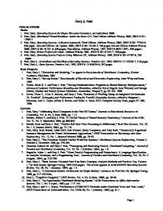
The workflow community is moving rapidly to address interoperability. Led by the Workflow Management Coalition (WfMC), standards for distributed workflow architectures and workflow interoperability are emerging and gaining momentum. The major contribution of the WfMC to date has been the development of the Workflow Reference Model[123] (see Figure 3). The Reference Model identifies the architectural components of a workflow system and the interfaces (called WAPIs1) between these components. At the center of the Reference Model is a Workflow Enactment Service, which is comprised of one or more Workflow Engines. Process definitions are constructed via a Process Definition Tool, and may be submitted to a Workflow Enactment Service via WAPI 1[124]. WAPI 1 also defines a process language known as WPDL for providing translational capabilities between different workflow representations. A workflow participant uses a Workflow Client Application to access the Workflow Enactment Service through WAPI 2[126]. This client
1. For Workflow Application Programming Interface[123]
29
Process Definition Tools Interface 1 Interface 5
Workflow API and Interchange formats
Interface 4 Other Workflow Enactment Service(s)
Workflow Enactment Service
Administration & Monitoring Tools
Workflow Engine(s)
Interface 2
Interface 3
Workflow Client Applications FIGURE 3.
Workflow Engine(s)
Invoked Applications
WfMC Reference Model (from [123])
application, referred to as a Worklist Handler, allows the user to retrieve the set of tasks to perform. The Workflow Enactment Service may make use of external tools, called Invoked Applications in the Reference Model, to support enactment1. WAPI 4[127] provides an interoperability interface between Workflow Enactment Services. It provides run-time support for coordinating workflow executions by two or more services. WAPI 5[129] defines an interface for Administration functions, and provides an Audit Data specification for preserving process histories.
2.3.2 Software Process Support The software engineering community is realizing the need for predictable, understandable, and manageable software processes, exemplified by the development of the Capability Maturity Model (CMM)[92] by the Software Engineering Institute (SEI) at Carnegie-Mellon University. Researchers in software engineering are pursuing realizations of Process-centered Software Engineering Environments (PSEEs) that provide 1. While the Reference Model shows two separate interfaces for the Worklist Handler and the Invoked Applications, the specification of the two has recently been subsumed entirely into WAPI 2[126].
30
automated assistance to software developers’ activities. It is hoped that automated support will assist organizations in performing several key practices of the CMM. Christie[23] indicates that a PSEE can most effectively be applied at levels 2 and 3 of the CMM, the Repeatable and Defined levels. Sorenson[106] argues that workflow products can assist metrics collection, a key practice for organizations at Level 4 (Managed) who are looking to go to Level 5 (Optimizing). Rains[96] provides a detailed mapping of how workflow can support Key Practice Areas (KPAs) of CMM Level 3 (Defined). His review of the seven KPAs of Level 3 show value-added by workflow tools in each of these areas. The primary benefits derive from having a consistent, defined process, resulting in better communication and coordination between developers.
A primary focus of software process research over the last decade has been on software process representations. Various formalisms are proposed in the literature and debated with respect to desired goals for constructing software process models. This debate is entirely worthwhile; the result is a better understanding of the intricacies of software processes and the semantics required of such processes. However, these PSEEs are monolithic due to their inability to support heterogeneous process representations and architectures in an open fashion. The software engineering community is beginning to recognize the need for supporting interoperability and reuse of heterogeneous software process models.
Defining some standardized way to represent software process models or at least provide some uniform concepts is seen as central to the ability to create interoperable and reusable software process models. If heterogeneous models conform to some standard, can be translated to some common intermediate form, or at least be expressed using a common vocabulary, then the potential for interoperability increases. Contrary to the work of the WfMC, there is no standardization body or de facto accepted standard in the area of enactable software process modeling. In terms of enactable software process models, the work of the past decade has focused primarily on different process representations, and to some extent architectural support issues. Only recently has more attention been paid to “standard” software process models, or unifying theories on software process modeling concepts. Section 2.4 reviews these contributions in detail.
31
2.3.3 Comparing Automated Workflow and Software Process Support The relationship between automated workflow and automated software process support is fairly obvious at the conceptual level. Both are process-oriented, modeling a process at a sufficient level of detail, and providing the infrastructure to support enactment of the model. In essence, a software process modeled to an enactable level of detail is a workflow. Both areas address similar representation and infrastructure issues. Both share some of the same concerns. Each faces increasingly complex requirements brought on by new technology, the need to support collaborative work, the ability to support geographically distributed teams, and the need to support inter-organizational or cross-functional unit processes. Both are also motivated by similar factors, such as process understanding, analysis, communication, reducing cycle time, increasing quality, and increasing productivity. Both suffer from a lack of interoperability and reuse.
Despite these overlapping considerations, there remains reasons to treat automated workflow and software process separately. Automated workflow normally refers to the automating of business processes, which are relatively short in duration (minutes, hours, days), are fairly stable (in the sense the process definition is not changed often, and if so is done off-line by a Business Process Reengineer), and usually involves data-centric tasks that do not require sophisticated software tools[46]. In contrast, software processes can be of much longer duration (hours, days, weeks), are relatively unstable (in the sense the development activities may be changed or refined as the process is enacted), and involves creative tasks that require the integration of sophisticated software tools to assist the performers of the process[24][33]. Furthermore, automated workflow and software process modeling have evolved independently, and to date workflow is industry-driven while very few commercial PSEEs are on the market. As seen in this section, there is a mature industry in automated workflow addressing interoperability and other issues. The software process support industry lacks this maturity, but has a very active research community addressing the most difficult aspects on automated process support1. 1. There is relatively little cross-fertilization of these areas. The workflow industry has emerged with a set of useful tools and emerging standards, while the software process community has addressed issues of dynamicity and process improvement. While some researchers address both areas, there has been more overlap than cross-fertilization.
32
The need for interoperability and reuse in automated workflow and software process modeling motivates the application of a component-based approach to both areas. Therefore, in this research, the utility of the OPC approach is presented with respect to both areas. Although from a modeling perspective I consider enactable software processes to be a subset of automated workflow, the distinction between the two areas will be kept throughout this work wherever relevant due to the unique characteristics of the enactable software process modeling domain and the independent evolution of the two areas.
2.4 Techniques for Interoperability and Reuse Interoperability and reuse are increasingly important issues in both the workflow and software process communities. There is increasing standardization and research activity addressing these issues. This section categorizes these activities along four dimensions: 1) Identifying an underlying theoretical foundation for process, 2) Defining a common translation language for process representation, 3) Providing control interoperability between separate, distributed process support environments, and 4) Applying object-oriented and component technology to process support. Each of these dimensions is addressed in this section.
2.4.1 Common Theoretical Foundations There are attempts in the literature to provide a common theoretical foundation for process by defining a generic process vocabulary or schema. The vocabulary identifies concepts common in most every representation of process. It is then expected that such a common foundation can serve as a catalyst for accepted standards in process support. The majority of these efforts are in the software process community, which is less mature than the workflow community but addressing more complex issues. As seen in the next section, the workflow community is already developing standards based on accepted foundations. This section discusses efforts to identify common process vocabularies and schemas in the literature.
2.4.1.1 Common Process Vocabularies Lonchamp[71] attempts to give software process engineering a firm foundation by defining relevant terminology using what he calls a “descriptive lexicography” approach. With this approach, Lonchamp clarifies
33
the meaning of several words and phrases used in the software process engineering literature. As part of the lexicographical breakdown, Lonchamp provides a framework in which a general terms are identified, as well as terms specific to subdomains for software process modeling and process-centered software engineering environments. Among the terms defined in the general universe of discourse are Software process, Process step, Activity, Task, Agent, Resource, Role, Constraint, and Software process engineering. These terms are of interest since they identify commonly held abstractions in the software process literature. However, despite the identification of common terms in the universe of discourse, this paper does not suggest how exactly a general theory of software process can be constructed to promote interoperability and reuse.
Feiler and Humphrey[39] define software process terminology for the purpose of better communication. The definitions are organized in a framework so the vocabulary can be extended in a systematic way. First, a few general definitions are given for Process, Process Step, Process Element, Process Script, and Process Program. The framework is then extended for terms related to the areas of process definition, process engineering, process enactment (with subcategories for enactment, control, authority, and assurance), and process properties (with subcategories for static and dynamic properties). The paper then gives examples of domainspecific definitions built from these definitions. The result is an extensive vocabulary of process terms. The authors provide more information on how the vocabulary can be applied than Lonchamp through examples and a useful up-front discussion on current needs in software process engineering.
Conradi, Fernstrom, and Fuggetta[28] provide definitions for Process, Activity, Role, Agent, Tool, Artifact, Project, and Production Support as “basic concepts”, and also define process modeling concepts: Production Process, Meta-process, Process Model, Process Support, and Process Modeling Language. Riddle[99] also identifies and defines a set of process terms including Process Step, Work Product, Role, Condition, Performer, Method, and Operation. What the reader should gather from the terms identified by Conradi et. al.[28], Riddle[99], and the vocabularies described above is the high degree of overlap in the sets of terms identified in each paper. This is indicative of the emerging maturity of software process automation.
34
In the workflow community, the WfMC has published a glossary[122] of process terms. This glossary has the advantage of being backed by a standards organization; hence its terms are widely accepted in the workflow community. This is another example of the relative maturity of workflow and software process.
2.4.1.2 Common Process Schemas One approach for developing a unifying theory of enactable software process modeling is the “common conceptual schema” approach. In this approach, a common generic schema is proposed that consists of a set of entities and relationships between these entities that should exist in all process models. This is the approach taken by Armitage and Kellner[6]. The authors argue that the proliferation of process modeling languages coupled with the varying objectives one might have for constructing the model implies that no one language is suitable for process modeling. Instead, they propose a conceptual schema that represents “a single, integrated view of the information content needed in process definitions and models” ([6], p. 154). The benefits of this approach they claim include a basis for representation and transformation, and as a process storage representation for library-based reuse. The schema consists of three basic entities, Activities, Artifacts, and Agents, the relationships between them, and a set of behaviors. Relationships may be between entities of the same or different types. Examples include activity decomposition, agents performing activities, activities producing artifacts, and so forth. Behaviors represent control information (similar to the behavioral view presented in [48]), including such things as when activities can begin, under what conditions they can terminate, and decision-making information. The specific schema the authors propose is not inconsistent with the basic abstractions employed for OPC. The authors argue such a schema is useful as a common representational format that allows for interoperability and reuse.
The PCIS LCPS1 model[35][82] identifies basic process entities and the relationships between them in the entity-relationship model shown in Figure 4. PCIS LCPS is centered on the relationship between Activities and Products. Activities produce or consume Products. Relationships between Activities and other entities
1. Portable Common Interface Set Life Cycle Process Support
35
tool
employs
has_sub
has_sub
role
activity
has_input has_intermediate
assigned_to
product
has_output governed_by
can_perform
has_version
agent
has_variant
direction Triangles point in the directions the relationships are read FIGURE 4.
PCIS LCPS Model (from [82])
in the model indicate additional resources or constraints on a process model. Activities employ Tools to assist in carrying out the Activity. Every Activity is assigned to a Role, which identifies who is responsible for the Activity. Human or automated Agents perform Roles. Finally, each Activity has associated Directions, which represent objectives, constraints, or guidance for the Activity. Similar to [6], the PCIS LCPS defines useful abstractions for process models. However, instead of proposing that process definers translate representations to the PCIS LCPS schema as in [6], the creators of the PCIS LCPS model propose that the model be refined to a level of enactable detail. Consistent with the terminology in Lonchamp[71] and Conradi et al[29], PCIS LCPS is in this sense a Generic Process Model that is refinable to a Customized Process Model, which in turn may be transformed to an Instantiated Process Model. The basic abstractions of the OPC framework are derived in part from the PCIS LCPS.
36
PCIS LCPS goes beyond the common conceptual schema approach to identify the activities of process definition and enactment as processes. The process of defining and enacting a process is called the meta-process. The meta-process is important from the perspective of defining the activities, products, and roles (rights) of the meta-process with respect to the process. Included here is the identification of Activity states and the operations that allow Activities to transition between states. Abstraction of process state is not unique to PCIS LCPS (see Section 2.2), and is also a fundamental abstraction in the OPC framework.
2.4.2 Common Translation Languages The process vocabularies and schemas proposed in the previous section primarily reflect a maturing of the software engineering community in the area of automated software process support. In the domain of automated workflow, converging ideas are expressed by the emerging standards of the WfMC. The workflow community is relatively older and more mature than the software process community, and has gone beyond defining common vocabularies and schemas, but also to defining a common language for translation. This language, the Workflow Process Definition Language (WPDL), is defined in the WAPI 1 specification. Although the WfMC is the standards organization in the workflow community, other more research-oriented efforts are also defining process languages for interoperability. Two of these efforts, the Process Interchange Format (PIF) and the Process Specification Language (PSL), are more general in their scope and approach than WPDL, but both target workflow as a potential application domain. The PIF and PSL working groups are hoping to propose these process languages as standards in the near future. This section discusses WPDL, PIF, and PSL.
2.4.2.1 WPDL WAPI 1[124] defines the interface between process definition tools and workflow enactment services. The goal, in principle, is to allow for process definitions constructed by any process definition tool to be enacted by any workflow enactment service. The use of a process definition tool implies the resulting definition be constructed in some notation (e.g. process definition languages or PDLs, petri nets, event-based, rule-based, etc.) that a corresponding enactment service interprets in order to execute the workflow. If the notation is not
37
native to the workflow interpreter, then some translation of the representation is required. WAPI 1 proposes WPDL as an interchange format for workflows. A WAPI 1 compliant workflow system provides import and export capabilities between its notation and WPDL as shown in Figure 5.
WPDL is derived from a meta-model for workflow. This meta-model is shown in Figure 6. A Workflow Process Model is comprised of four submodels: Workflow Process Definition Models, Workflow Participant Models, Workflow Relevant Data Models, and Workflow Application Models. The meta-model is considered activity-centered, in that a Workflow Process Model1 supports many Workflow Process Definitions by defining the scope of information available to the definitions. A Workflow Process Definition references the Workflow Relevant Data Model and the Workflow Application Model (as discussed below), and addition-
FIGURE 5.
Process Language Translation (from [124])
1. Note the distinction between a Workflow Process Model and a Workflow Process Definition.
38
ally defines Workflow Process Activities and Transitions. A Workflow Process Activity is of one of four types: an atomic activity, a subprocess reference, a loop, or a dummy (routing) activity.
Process definitions reference the Workflow Participant Model to assign roles and performers to activities. The Workflow Participant Model assigns a resource as the performer attribute of an activity. A resource may be a single person, a group of people, a computerized agent, or any arbitrarily defined resource that can perform activities. The WAPI 1 specification allows Organizational Models for defining activity participants, though organizational role mapping to process roles is not required. Definitions may reference attributes defined as Workflow Relevant Data. The scope of the attributes is either the Workflow Process Definition or the encompassing Workflow Process Model. The data may be of an arbitrarily complex type. The Workflow Application Model defines tools that support process enactment. A tool is a generic COTS tool, a custom enterprise service, or a procedure of the workflow management system. Due to the variation in the meaning of tool and the ways to interface with such tools, the Workflow Application Model interface is fairly small.
The WAPI 1 specification has clearly matured since its first beta release in May of 1996[124]. WPDL is a well-defined and detailed meta-language derived from a robust meta-model. The meta-model and WPDL allow for extensibility through vendor-specific interpretations of the submodels identified in the metamodel. These interpretations are realized through interface “hooks” that can be defined in WPDL itself.
39
FIGURE 6.
WfMC WAPI 1Meta-model (from [124])
Despite the maturation of this specification, its practical use still largely depends on a priori agreement between vendors on extended attributes and data types. The language has few required attributes for its constituent entities, and the specification admits that without definition of a sufficient number of optional attributes, the result model instantiation is not very useful ([125], p.69). Nowhere is it stated what minimal set(s) of attributes comprise a useful model instantiation. Therefore, to usefully apply WPDL, some knowledge of the attributes that will be available in the end model is needed. In this sense, WPDL is more of a framework for having two process languages map to each other as opposed to mapping to and from an intermediary language. Furthermore, the specification assumes the existence of a Process Repository that holds Workflow Process Models, but no specification of the interface of such a repository is offered. Instead, the functionality and scope of the repository is assumed throughout the specification. A Process Repository is not part of the Workflow Reference Model (see Figure 3).
40
WAPI 1 is a translational approach to interoperability and reuse (see Figure 5). Translational approaches often force particular semantics on conforming process representations, though in the case of WPDL the problem may be that not enough information is required to make the resulting models useful. While WPDL provides many levels of scoping, encapsulation is not provided to the level offered in a component-based approach. WPDL also omits the definition of typed data artifacts, or products, as top-level entities in the meta-model. While Workflow Relevant Data may be expanded to include coarse-grained data, it is clearly not the intent. Typed products are included in the OPC specification. Finally, the WAPI 1 specification “defines a formal separation between the development and run-time environments” ([125], p.8), which artificially introduces barriers to handling run-time complexity. OPC encapsulates definition and enactment state within a single component in order to handle dynamic complexity.
2.4.2.2 PIF The Process Interchange Format (PIF) Working Group has developed the PIF specification[70] for supporting the interchange of business process representations. The PIF Working Group is pursuing the development of a common translation language (PIF-Core), translators between PIF and process representations, and mechanisms for extending PIF (PIF-PSVs, or Partially Shared Views).
PIF is a translational approach in the same vein as the WfMC’s WPDL specification (see Figure 5). PIF-conforming workflow representations provide a translation to PIF and from PIF back to the original representation. PIF serves as the common language through which heterogeneous process representations are mapped. The goal of PIF is to provide a high-level generic translation language that is highly flexible and extendable, as opposed to a language which is efficient and provides sufficient detail for enactment.
The PIF schema is shown in Figure 7.
41
Component
ENTITY
Documentation
User-Attributes
CLASS
Name Capability
Constraint
Status
Attribute
SUCCESSOR
Preceding-Activity Succeeding-Activity
ACTIVITY-STATUS CREATES
AGENT
Object
Activity
Activity
Activity
ACTIVITY
MODIFIES
Object
OBJECT
Activity
When
USES
Object
Activity PERFORMS
Actor Then Else
TIMEPOINT
Begin End
Preceding Timepoint
Precondition Postcondition
Succeeding Timepoint
DECISION
BEFORE
FIGURE 7.
PIF Schema (from [70])
PIF defines a core language called PIF-CORE, and a mechanism for extending the core known as Partially Shared Views (PSVs). PIF defines language constructs in frames, where each frame defines a process entity. Within each frame, attributes are defined for each entity. Frames may be related through inheritance, in which case a particular frame inherits the attributes of its parents. Frame instances may be related by having one frame possess an attribute whose type is another frame instance, or in many cases relations are represented as first class objects by defining a frame for the relation (e.g. CREATES, MODIFIES, and USES are subclasses of frame RELATION).
In PIF, all classes derive from class ENTITY. The four special types of ENTITY (ACTIVITY, OBJECT, TIMEPOINT, and RELATION) form the building blocks of a process definition in PIF: “a process is a set of ACTIVITIES that stand in certain RELATIONS to one another and to OBJECTS over TIMEPOINTS” ([70], p. 9). PIF-CORE is a minimalist approach to capturing commonalities across workflow representations. PIF-CORE identifies entities, or objects, represented as frames and related in a hierarchical fashion.
42
Partially-shared views (PSVs) extend the PIF-CORE by defining interchange formats between native representations and PIF objects.
The PIF model shown in Figure 7 has similarities with the WfMC meta-model for WPDL shown in Figure 6. Activity decomposition is supported in PIF through the Component relation of an ENTITY to itself. A performer is defined as an OBJECT1 relating to an ACTIVITY through the PERFORMS relation. However, PIF has several differences with the WfMC meta-model for WPDL. Time is explicitly represented in PIF’s Temporal Relations PSV, and there is more detail on the temporal relations between activities than there is in WPDL. PIF also includes conditional expressions in the core through the DECISION entity, while WPDL does not. The CREATES, MODIFIES, and USES relations to OBJECT is a more general mechanism for expressing dataflow, external tool usage, and resource usage than Workflow Relevant Data and Workflow Applications in WPDL.
PIF and WPDL are both minimal languages whose intended use is translation between vendor-specific workflow representations. PIF is a smaller and more general language than WPDL, while WPDL is more detailed in its specification of attributes and scope issues, and hence more readily usable than PIF. The basis of the PIF approach is in many ways consistent with the OPC view. PIF encourages extensibility through hierarchical relationships between frames and support of PSVs. OPC provides extensibility through objectoriented inheritance that includes functional, or method inheritance in addition to the attribute-based inheritance defined in PIF. The primary difference is intent. PIF is intended for general purpose translation, and as such does not provide the detail to provide enactable support for interoperable processes. OPC is a framework for interoperable enactable processes, and not for translation. Any approach to interoperability based on a common representation language will encounter problems gaining conformance from individual representations since some representations will be inherently easier than others to map to the common language.
1. PERFORMS does not relate directly to AGENT but instead to OBJECT, and AGENT derives from OBJECT. It is not clear why PERFORMS does not relate directly to AGENT, as the specification itself states “An AGENT represents a person, group, or other entity (such as a computer program) that participates in a process.” ([70], p. 13).
43
This research argues that a truly object-oriented, component-based approach that encapsulates representation-specific details behind well-defined interfaces will allow for more widespread conformance, resulting in greater potential for interoperability and reuse.
2.4.2.3 PSL The Process Specification Language (PSL) project of the Manufacturing Systems Integration Division at the National Institute of Standards and Technology (NIST) has a broader set of application domains than just workflow. According to [103], target domains include process planning, scheduling, simulation, project management, business process reengineering, and product realization process modeling in addition to workflow. The goal of the project is capture the concept of process through a generic representation. The project is still ongoing, but at this stage the approach is far more formal than WPDL and PIF.
PSL files[56] are composed of Class declarations with a header providing documentation (Annotation file attribute) and a default Ontology. PSL Class structures resemble the frame structures found in PIF. A Class identifies a set of related attributes, some of which are predefined, and the rest of which are user-defined. Predefined attributes are Annotation, Ontology, and Parameters. Annotation and Ontology attribute values override the values of the corresponding file-level attributes if they are provided. User-definable attributes are either Values, Conditions, or ProcessSteps. Each attribute may be bound to a single value, a list of values, or a set of values. Special rules govern the instantiation of classes based on the way the class is instantiated and the values of specific attributes. The details are not relevant here, but it is important to note that PSL files are declarative, and as such specify information about a process situated in some environment1, as opposed to providing language constructs for executing processes.
The central idea behind this formal approach is the concept of shared ontologies. In PSL, an ontology is used to interpret the meaning of declarative expressions in attribute-value pairings. These expressions can only be
1. The examples in the PSL specification quickly reminds one of situation calculus. In fact, situation calculus is one of the foundation theories supporting the PSL-CORE ontology.
44
meaningfully interpreted with respect to the ontology (specified at either the class or file level). Therefore, in order to translate between two process representations, the ontology of both representations must be made explicit, and the overlap between the ontologies forms a shared semantic base1.
PSL is an ambitious attempt to formally define the generic concept of process. The challenge is significant, and the prospect for wide applicability of such a formal proposed standard are questionable given its scope and formality. The ontologies PSL requires may be easier to construct in well-understood domains such as production scheduling environments than in the domains of workflow and software process that concern this research. Despite these issues, PSL represents a serious attempt at providing a formal basis for process, and as such makes an important contribution to the area.
The philosophy behind OPC differs from the translational approach of WPDL, PIF, and PSL. OPC components are encapsulated process entities that interoperate in meaningful ways to produce workflows. A minimalistic framework is provided that eliminates dependencies on specific attributes. The framework is extendable so that representation-specific abstractions may be utilized. Translation between heterogeneous process representations is not required.
2.4.3 Interoperability between Multiple Process Support Environments Section 2.4.1 and Section 2.4.2 discuss interoperability through the definition of common abstractions and/ or common languages for process data interchange. The theoretical foundations discussed in Section 2.4.1 further understanding and communication in the process field, though they rarely provide the detail to specify how interoperability is achieved. The common languages presented in Section 2.4.2 push the abstractions down a level, developing languages as a means of expressing process meta-models. These languages advocate a data integration approach, by defining translations between representations or defining protocols for process data interchange. In this section, approaches to interoperability based on distributed control integra-
1. An ontology is constructed from other ontologies or from foundational theories (domain-independent axioms). It is unclear if an ontology is canonical within a domain, or if a mapping between ontologies can expand the shared space.
45
tion are discussed. These approaches are oriented toward control protocols by which one process service cooperates with another process service. “Cooperating” service protocols define interfaces for service requests and service responses. Instead of focusing on representations, these protocols concern themselves with distributed architectures for scaleability and interoperability.
2.4.3.1 WfMC WAPI 4 WAPI 4[127] is the abstract interoperability specification of the WfMC. WAPI 4 defines distributed control integration protocols for workflow services. Being a control integration protocol means the specification defines operations for workflow services to provide if their functionality is to be accessed by other workflow services. WAPI 4 specifies operations for the selection, creation, and starting of process instances from process definitions. WAPI 4 does not address data integration issues. Specifically, WAPI 4 does not specify the format for process information that is exchanged between two workflow services. While the specification recommends using WPDL (from WAPI 1[124], see Section 2.4.2.1) for this purpose, it does not require it.
WAPI 4 describes three different models of interoperability that govern interactions between workflow services. These are chained processes, nested subprocesses, and parallel synchronized processes. A chained process is the simplest case, where one workflow service (or engine), while enacting a process instance, triggers the enactment of a process instance on a second workflow service. This situation is shown in Figure 8. Once the second process instance is running, the first instance may or may not terminate. In either situation, the two processes do not rendezvous at some later point, and therefore do not exchange process information.
Nested subprocesses, shown in Figure 9, are similar to chained processes, except there is an explicit return from the spawned process on the second workflow service. The first workflow service suspends execution
Workflow Engine A
Workflow Engine B
FIGURE 8.
Chained processes (from [127])
46
Workflow Engine A
Workflow Engine B FIGURE 9.
Nested subprocesses (from [127])
of its current instance until the second instance returns. In this way, the second instance acts as a subprocess of the first instance.
Parallel synchronized processes rendezvous at some point in the middle of their execution. The process instances in this situation are already running, but at some point in both process definitions, a rendezvous with the other process instance is specified. This scenario, although interesting, is not currently addressed by the WAPI 4 specification.
WAPI 4 specifies operations for creating process instances, setting and getting process instance attributes, starting, aborting, terminating, and changing process instance states, and retrieving the current set of process instances. The specification is small in terms of the number of operations specified, but is complete in it coverage of the behaviors needed to select, create, start, and (optionally) monitor process instances across multiple workflow services.
WAPI 4 also discusses several practical issues in providing interoperable, distributed workflow services. The specification discusses the differences between asynchronous and synchronous services. Synchronous services must remain available for the entire lifetime of cooperating process instances. The WAPI 4 operations therefore have a distinctly asynchronous flavor, using request-response pairs between services to accomplish work. The specification discusses the different arrangements of how process definitions are stored and how they can be selected. Process definitions may reside on one or the other of the engines, or in some shared repository. The specification also considers efficiency issues, to the extent of describing a batch-oriented interaction between two services. Indicative of the practical nature of this specification, it has
47
been realized in a MIME binding[128], and has been implemented by several vendors[131]. The SWAP effort (see Section 2.4.3.3 below), is a related effort defining workflow interoperability services over HTTP roughly following the WAPI 4 specification.
WAPI 4 addresses control integration, as opposed to WAPI 1 addressing data integration. WAPI 4 is more grounded and mature, though providing control integration is somewhat easier since it avoids the need for the complex meta-models that are required when defining language. The only interoperability models required for the control aspect are the chained, nested, and parallel synchronized models. Despite achieving some consensus and maturity in the workflow community, the WAPI 4 specification does not cover a wide variety of interesting scenarios, primarily due to its consideration of only the chained and nested scenarios. The specification argues that this covers most of the practical scenarios in today’s environments, but it is clear that these are not the only interesting scenarios.
2.4.3.2 jFlow In May of 1997 the Object Management Group (OMG) put out a Workflow Facility RFP[85]. There were originally four submissions to the RFP, and in July, 1998, a submission sponsored by the WfMC, named jFlow, was adopted. jFlow[86] is an objectization of the existing standards of the WfMC. In particular, interface specifications were adapted from WAPI 2, WAPI 4, and part of WAPI 5. Interestingly, WAPI 1 is the only WAPI specification that is not incorporated into jFlow, since jFlow addresses run-time support issues, not build-time (or development, as termed in WAPI 1) support issues.
jFlow is important in that it maps the WAPI specifications onto an increasingly popular middleware platform, CORBA. Defining a workflow facility on top of CORBA provides scaleability, and resolves troublesome low-level issues included in early versions of the WAPI specifications for free by building off of already adopted OMG specifications1. Furthermore, it should promote adoption of workflow standards.
1. For example, COS Transaction Services and the COS Event Services may be useful for the workflow facility.
48
However, from the perspective of this research, jFlow does not add any fundamentally new concepts, but instead adapts the concepts of the existing WAPI specifications1, and so is not considered further here.
2.4.3.3 SWAP There is a current effort in the workflow community at defining a workflow interoperability standard over HTTP (Hyper-Text Transfer Protocol), the protocol of the Web. This effort is named SWAP, for Simple Workflow Access Protocol. The SWAP draft specification[110] defines an extended set of HTTP methods and a data interchange structure using XML (eXtended Markup Language). SWAP allows for control integration of generic asynchronous services in a wide-area environment. As such, SWAP may be applied outside of workflow for the control of any generic asynchronous service, though it is intent of the designers to apply SWAP to workflow. SWAP is an asynchronous service due to the long-running nature of workflow transactions. An asynchronous request is made to execute a service, and additional requests are made during the period of service execution to monitor progress of the long-running transaction. When the service completes, it notifies interested observers of its completion.
SWAP defines three fundamental resource interfaces2: ProcessDefinition, ProcessInstance, and Observer. A ProcessDefinition interface defines a factory for a service. It knows how to create unique instances of a service type, and returns this unique identifier to the requestor. A ProcessInstance refers to the generic asynchronous service itself, and is the performer of the service. The service instance is unique and runs only once. An Observer interface is provided by a party interested in process instances. A ProcessInstance is responsible for notifying interested observers through this interface. A special type of Observer called an ActivityObserver is used by a process instance to indicate it is waiting on an external service to complete. The external service may itself be another ProcessInstance, thereby creating the ability to construct subprocess or dependency relationships. SWAP goes on to define specializations of ProcessInstance for providing
1. This is certainly not a negative statement, but rather a strength of OMG’s technology adoption process. 2. SWAP uses the term resource to avoid implying that each entity must be an object. The implementation of a resource is independent of SWAP; SWAP merely defines a protocol for accessing resources.
49
a WorkItem interface and of ProcessDefinition for providing a WorkItemFactory interface. These interfaces facilitate managing a user-oriented view of tasks and task definitions in a multi-server environment. SWAP also includes process state and transitions as part of the interface on ProcessInstance that are consistent with the WfMC approach to process state.
SWAP participants have recently drafted a charter for an Internet working group. The relationship of SWAP to the WfMC is still being debated, although the draft specification[110] acknowledges that SWAP can be seen as a “loose binding” of WAPI 4 for HTTP. Like the jFlow effort, SWAP is more important from the perspective of trying to define standards over new and emerging technologies. In the case of jFlow the technology is CORBA, in the case of SWAP it is the World-Wide Web (HTTP and XML).
2.4.3.4 PCIS2 PCIS2[93] is a framework for wide-area tool integration built on Java, CORBA, and the Web. The PCIS2 framework defines an infrastructure for software engineering by providing a set of services upon which domain-specific tool suites can be integrated. PCIS2 framework services include User Administration, Configuration and Version Management, Traceability, Meta-data, Data Transfer, and Process.
The PCIS2 Process service combines ideas from PCIS LCPS (see Section 2.4.1.2), WfMC WAPI specifications (Section 2.4.2.1 and Section 2.4.3.1), jFlow (Section 2.4.3.2), and OPC. PCIS2 Process defines an object model for process and an architecture pattern for process services. In the PCIS2 Process object model, shown in Figure 10, a ProcessInstance is associated with Products and Roles, and Roles are associated with Agents. PCIS2 incorporates an explicit objectization of process states and transitions, as is done in jFlow and OPC. ProcessModel objects serve as factories for generating ProcessInstance objects, a commonly held abstraction in meta-models such as the WPDL meta-model. Note, however, that not all ProcessInstances are generated from ProcessModels; PCIS2 allows for AdHocInstances to be created without the benefit of an a priori model. This allows users to create ad hoc processes on the fly and attach them to existing processes.
50
ProcessFactory ProductFactory
0..* 1..1
has_input 0..* 0..*
0..*
ProcessInstance
1..1 1..1
0..* ProcessModel
1..1
1..1
1..1
stores
hosts
0..*
1..1
ProcessWrapper
generates
has_output
ProductMeasurement
1..1
generator for has_sub
0..*Product
mayImplement
hosts
1..1
1..1
1..1
0..*
1..1
generator_for
1..1
0..*
1..1 1..1
1..1
0..1
1..1 1..1
0..*
ProcessHistory
0..*
has_sub
User
responsible_for
1..1 has_sub
assigned_to 1..1 AdHocInstance
Agent 1..*
1..1
can_perform
1..1 ModelInstance
EnactmentState
1..1 1..* Role
1..1 ModelState
ProcessState
1..1 EnactmentSTD
1..1 ProcessSTD
ModelSTD
FIGURE 10.
PCIS2 Process Object Model (from [93])
The PCIS2 Process object model provides an object vocabulary for process in a CORBA environment. It does not define how two or more process services interoperate with one another to provide a uniform process service to the end user. For this purpose, PCIS2 defines a design pattern for wide-area service integration in a distributed architecture. This design pattern is shown in Figure 11.
51
a ccesses
Serv ice View 0..*
P2_ Clie nt 1..1
1..* con n ects_ to surro g a teFo r
c rea t es
P2_ Framewo rkService 1..1 h o sts 1..*
P2_ Serv er 1..1 d efa ult
P2_ Serv ice h o sts
Pro v id er
1 Serv iceBroker
1..* FIGURE 11.
PCIS2 Architecture Pattern (from [93])
An instantiation of this pattern for process is shown in Figure 12. The PCIS2 service pattern is centered on a service interface definition as defined by the PCIS2 specification. For process, this interface is defined by the ProcessWrapper object shown in Figure 10. The implementation of the service comes from one or more wrapped process tools, referred to as Providers in the pattern. Each tool is wrapped to provide the service interface. Two or more process services may also be combined by an intelligent ProcessBroker, which defines how two or more tools are to be combined to provide the service. The service interface is exposed to end user client tools through views, which partition the service interface into functional areas accessible to different types of users. Four views are defined in the PCIS2 Process specification: ProcessDefiner, ProcessPerformer, ProcessAuditor, and ProcessOwner, corresponding roughly with the control rights defined in the PCIS LCPS model and the meta-roles defined in OPC (see Chapter 3).
52
DefinerView
P2_Client
accesses PerformerView
connects_to
OwnerView
crea tes A uditorView
P2_Server
surrogate_for hosts d efau lt
hosts
ProcessService
ProcessBroker
hosts ProcessWrapper1
FIGURE 12.
ProcessWrapper2
Process Wrapper3
PCIS2 Common Concepts Pattern instantiated for Process (from [93])
PCIS2 provides process interoperability by wrapping process tools to a common object interface, or type, and then providing mechanisms for brokering between services and providing different views of services. Wrapping to a common interface is not unlike the WfMC WAPI 4 approach, though PCIS2 does not define direct control integration between process services in the same manner. WAPI 4 defines an interface between Workflow Enactment Services, providing the means for one such service to invoke the other service. PCIS2 does not define an interface, or view, specifically for services to invoke one another. Instead, it defines a uniform interface for clients of services to use, be they other process services, other PCIS2 Framework services, or end users. In this sense it is closer in spirit to the SWAP specification.
53
2.4.3.5 Oz Oz[9][10] provides homogeneous multi-site software process support. Process support is federated, spanning multiple sites, where a site is a particular instance of a domain. Sites may or may not be geographically distributed; what is important is that a site defines the logical boundary of a Process-Centered Environment (PCE). The PCEs in a multi-site instance are homogeneous in that each participating process server is of the same type. This is a simplifying assumption since it removes the complexity of dealing with heterogeneous process representations, type restrictions on process relevant data, and differing invocation protocols.
Motivated by techniques in distributed and federated database research, Oz employs an International Alliance metaphor, where disparate sites form Treaties to set up cooperative process models, and participate in Summits to enact Treaties. Each participant in the Treaty maintains as much local autonomy as possible; meaning a site maintains control over local process data, local process execution, and may withdraw from a Treaty at any time. A site only exposes as much or as little process information as is desired in order to participate in the cooperative process. A Summit occurs when the cooperative process is ready to be enacted.
This type of interoperability is similar to that of the WfMC’s WAPI 4, SWAP, and PCIS2 - interoperability between process services. However, a major deficiency in this approach is that the process services are homogeneous. This assumption removes much of the complexity involved in real-world scenarios, such as the need to translate process data and provide uniform interfaces for heterogeneous services. Part of the motivation for this assumption is confusing, since the authors state for heterogeneous approaches, run-time integration is impossible. Yet later in the paper they propose a hypothetical heterogeneous integration scenario with Oz and the ProcessWall system. Furthermore, WAPIs 1 and 4, jFlow, PCIS2, and SWAP already address these issues in heterogeneous environments. In any event, the results of implementing the proposed heterogeneous integration will be of great interest.
Despite the simplifying assumption of a homogeneous federated environment, the Treaty-Summit model is an interesting approach to multi-site federated PCEs. The authors also explore possible variations on distrib-
54
uted architectures to support multi-site homogeneous and heterogeneous PCEs[10]. In multi-site environments, some type of “glue” code is required between sites; the authors refer to this glue as the Foundation Layer. The architecture variations explore whether the Foundation Layer is centralized or distributed, and how this layer is integrated into the existing PCE. Similar variations are explored for CORBA-based distributed workflow architectures in [78].
2.4.3.6 ProcessWall and Mentor Two other projects discussed in [10], ProcessWall and Mentor, deserve some mention in this section. The ProcessWall[50] architecture employs a client-server architecture, where heterogeneous process client applications manipulate a central process state server. Communication is bidirectional between the client and server, so the client can manipulate a shared process state model, and receive notifications of updates to the model. While the process client applications may be heterogeneous process support systems, they do require a common understanding of the server’s process state model.
The Mentor project[81][121] is a 3-tier architecture for scalable heterogeneous workflows. The authors correctly note that most all process architectures are 2-tier, with all process related data stored on a central server. Mentor distinguishes itself from other middleware approaches by combining its middleware architecture with formal state-activity charts (in the spirit of STATEMATE[48]). The state-activity charts are applied in a manner similar to ProcessWall[50] in that they serve as the common ground between heterogeneous processes. The authors note some problems with this approach, such as the ability to handle dynamic modifications caused by the addition of ad hoc activities.
2.4.4 Process Components In [9], the Oz authors advocate a systems approach to interoperability as opposed to a language-based approach. The authors claim that specifying process interfaces within a process modeling language (PML) is the wrong abstraction, though their motivation for this statement is not on separating interface and implementation in the object-oriented sense, but on sharing common subprocesses in a distributed environment.
55
Nevertheless, a component-based approach to process modeling and enactment uses interface and implementation separation to define boundaries between process fragments and reduce monolithic dependencies. Component-based process support also has ramifications for distributed process architectures, potentially changing the roles of architectural components, such as those identified in the WfMC Reference Model (see Section 2.3.1). In this sense, component-based process modeling does not fit the distinction between systembased and language-based approaches to interoperability described in [9], but has elements of both.
“Component” is a widely used term with several interpretations. “Component-based process support”, as it is applied in OPC, refers to the componentization of process information and behaviors. Ironically, there is a paper[59] on component-based process support done by the Oz group, but this is an approach to componentizing the architecture and tools of the Oz environment, and not an approach to component-based process modeling. Other projects, SPMS, Pynode, and DartFlow, in spirit take a conceptually similar approach as OPC. These projects are discussed in this section.
2.4.4.1 SPMS The Software Process Management System (SPMS) described in Krasner et. al.[69] discusses process components as “named collections of process fragments organized into some meaningful subnetwork” ([69], p.92). A process component represents a process fragment at some level of granularity and complexity, which is elaborated to produce the necessary detail for enactment. Process models are constructed from process components as both a hierarchy of components and a network of information flow between components. The authors discuss an example usage where process fragments were placed in a process database for reuse in coarser-grained process models.
Krasner et. al.[69] describes some of the goals of a component-based approach without describing much of the machinery behind component-based process support. A rigorous definition of what is a process component is not given, nor is a description of how components are implemented. In general, the term component is used conceptually for describing reusable process fragments, but the machinery behind developing com-
56
ponents is not specified. This is not surprising given the timeframe (1992) when this paper was published, before the current boom in component-based software development.
2.4.4.2 Pynode A more detailed description of the machinery required to realize process components is provided by Avrilionis, Belkhatir, and Cunin[7][8] on the Pynode project. The authors propose the construction of software process components for producing process artifacts. A “software process component” is essentially a process model fragment written in some Process Modeling Language (PML). Components are dynamically combined to construct complete process models through interface types and their respective “connectors ports”. The connection interface port types define input, output, and synchronization relations that allow components to dynamically interact. The exchange interface port types allow components to exchange information (read/write) in an asynchronous fashion during enactment. Process enactment is supported through the construction of execution views. An execution view defines a collection of components and composition relations between them. The dynamic composition of components through execution views together with the execution of the individual components comprise process enactment.
The component-based approach of Avrilionis, Belkhatir, and Cunin is similar in concept to the approach advocated in OPC. The authors correctly motivate the need to eliminate monolithic process systems and instead provide reuse and integration capabilities for process representations. The process modeling language of a component is separated from the component’s interface. Components are combined through welldefined interfaces to support dynamic composition. However, there are several differences with the OPC approach. The interfaces on components in the Pynode project are defined by synchronous and asynchronous ports. The capability of components to interact depends on the compatibility of the information types (signatures) that can be exchanged using these ports. No protocol for assuring compatibility is specified in either [7] or [8]. This is in contrast to the OPC framework, where common interfaces are supported by all process components. OPC also defines a set of abstractions aimed at commonality between approaches, in order to try and capture a large part of the common concepts found in the process domain (which are
57
described in this chapter). Furthermore, there is no presentation of how one integrates heterogeneous representations into Pynode. OPC provides an extendable framework for integrating new component types based on heterogeneous representations without modifying the existing framework, Despite these differences, the Pynode component approach is similar in philosophy and motivation to the OPC framework, and appears to be at roughly the same level of maturity. Results of these two experiments will be very useful to the software process modeling community.
2.4.4.3 DartFlow DartFlow[17] is a Web and agent based system for supporting workflows. DartFlow uses mobile agents to transport process fragments to users and resources enacting a process. DartFlow does not refer to itself as a component-based system, but many of the concepts of a component-based system are present in the form of agents. An agent in DartFlow is a transportable program that encapsulates business rules of a particular process fragment. Agents travel to user’s desktops, where they bind with information needed to carry out the process step they represent. When a process step completes, the agent carries the routing information necessary to determine where to go to next, without consulting a central workflow engine.
There are several concepts present in DartFlow that are shared with component-based approaches like OPC. Encapsulation of process logic is important in both DartFlow agents and OPC components. A DartFlow agent also “store some basic knowledge about its internal state and behavior” ([17], p. 6), which is similar to the process state and transitions abstraction present in OPC (see Chapter 3). DartFlow also presents a supporting architecture for transportable agents that includes services for exception handling and agent tracking. While OPC does not share the exact same services, it does require a supporting architecture that provide services not inherent in components themselves (see Chapter 3).
DartFlow is a specific architecture for realizing distributed workflow support in a manner that is similar in spirit to OPC. OPC is not based on a specific architecture however, and one could realize an OPC-compatible process support environment using an architecture1 not unlike the one described in [17].
58
2.5 Summary This chapter discusses current issues and approaches in automated process support. Topics covered included process technology adoption, technical issues, and the application domains of workflow and software process. The chapter concluded by focusing in detail on the issues of interoperability and reuse, motivating a new approach for providing open process environments. A component-based approach to process support provides a fundamentally new foundation for process technology. The ramifications of this approach may well reverberate across all phases of the process life cycle. It also holds the potential for introducing new process techniques in wide-area distribution, optimization, and process brokering. This research is just a first step, and does not address all possible ramifications. The first two chapters have laid out a vision of a component-based approach to process, and laid this vision in the context of current research in automated process support. The rest of this document turns its attention to the Open Process Components Framework. This framework addresses interoperability, reuse, dynamic processes, component-based process modeling, and component-based process supporting architectures. The contributions in these areas are discussed over the rest of this document, and summarized in Chapter 7. The next chapter presents the conceptual foundations of the framework, addressing the key issues discussed in this chapter.
1. In fact, an early version of OPC used migrating Java code to transport components to user’s desktops.
59
CHAPTER 3
A Conceptual Framework for Component-based Process Support
Chapter 1 presents a vision for component-based process support. Chapter 2 discusses issues and approaches in automated process support, focusing on interoperability and reuse. These chapters discuss the potential of a component-based approach for automated process support, but what does it mean to be a “componentbased approach”? This chapter provides a conceptual foundation for component-based process support by defining what a process component is, and on what foundations process components are derived.
3.1 Component-based Process Modeling In order to understand component-based process support, one must understand what it means to be a process component, and how the traditional activities of process modeling and enactment are performed in a component-based environment. OPC offers the following definitions:
• Process Component - a process component is an encapsulation of process information and behaviors at a given level of granularity.
• Component-based Process Model - a component-based process model is a collection of process components that interact in meaningful ways. A component-based process model is itself a process component.
• Component-based Process Enactment - component-based process enactment refers to the creation of a component, the dynamic evolution of the component, its interaction with other process components, and its interaction with users and an environment in which the component is situated.
These definitions are elaborated on in this section.
3.1.1 Process Components A process component is an encapsulation of process information and behaviors at a given level of granularity. The process information is expressed in whatever formalism or language is used to represent the semantics of the component. OPC separates this information three ways: process schema, process states and
61
transitions, and process implementation (see Figure 13). The process schema defines a vocabulary for the component, identifying entities and relationships that have meaning for a particular component. OPC defines a minimal, extendable, common schema for components. Process state and transitions between states are represented as a finite-state machine. The set of process states and valid transitions are defined per component, with a common set of meta-states identified within OPC. The process implementation is the underlying representation of the component and the machinery which interprets this representation. This may be a petri net, a process programming language, or whatever other means are used to represent process semantics. It may also be a process tool that has been wrapped to provide the process implementation. The implementation of the component is encapsulated within each component, so that components may interact without requiring homogeneous representations.
A process component provides two additional abstractions. One is a process type, which is a means of categorizing processes. The schema, states and transitions, and implementation define the object implementation of a component, but they do not say anything about what type of process a particular component represents.
Definer
a m he sc
Performer
state
ion t a t en m ple im FIGURE 13.
A process component
Observer
Owner
62
Two components with the same exact schema, states and transitions, and underlying implementation may represent two distinct processes, for example, a paper review process and a software development process. Likewise, two components with different schemas, states and transitions, and underlying implementations may both be insurance claims processing workflows. In OPC, a process type is defined for each component that indicates what type of process the component represents.
The second additional abstraction is meta-views. Meta-views define the allowable ways in which meta-roles expect to interact with process components. A meta-role identifies how the component is currently being used; for definition, enactment, ownership, or observation. A view is provided for each of the meta-roles that defines the way a given meta-role interacts with the component. OPC defines the four meta-roles just listed and their corresponding views. Additional meta-roles and views can be defined on a per component basis.
3.1.2 Component-based Process Models A component-based process model is a collection of process components that interact in meaningful ways. The “meaningful ways” in which components interact is a primary issue addressed in this research. OPC provides mechanisms for component interaction through well-defined interfaces, process events, and process messages. These mechanisms define a common contract by which all components abide. However, in order to prevent from prescribing a contract that is too rigid, these mechanisms are extendable and open.
A process model realized as a set of cooperating components is a step toward an environment of interoperable, reusable process fragments. Components are combined in an aggregation tree to support various levels
FIGURE 14.
A Process Component Tree
63
of process granularity. A component-based process model is itself a process component. OPC supports both top-down modeling and bottom-up reuse. A top-down process tree is constructed by decomposing process components at coarser levels to finer-grained process parts. Bottom-up reuse is supported by realizing a relation between two or more process parts as components. In terms of the process component abstractions discussed in Section 3.1.1, a subprocess component serves as part of the implementation of its parent process component. In terms of process granularity, a process component captures an abstraction of the process space at a particular level. The fact that the component may be composed of subprocess components is not exposed to the outside world.
3.1.3 Component-based Process Enactment Component-based process enactment refers to component creation, dynamic component evolution, component interactions with other process components and with its environment (including end users). A process component in OPC is an active, “living” entity. It encapsulates its own process schema, state, and implementation (see Section 3.1.1), and allows dynamic modification of itself based on its own implementation. For example, a process component may extend its schema instance1 during enactment, or a component may dynamically change its set of process states and transitions. Dynamic component modifications are managed by the component itself, reducing reliance on other components or global process information.
In OPC’s component-based approach, there is not a strict separation between process model and process instance. In that a component defines its own schema, states and transitions, and implementation, it defines its own process fragment. Process components evolve as they are enacted, activating subprocess components and instantiating itself as binding information becomes available. Hence each process component runs the gamut from creation to instantiation[29] during its active lifetime.
1. Changing a schema instance is different than changing the schema. For example, a process may determine it has a new Product, since Products are part of its schema. But it cannot suddenly decide that Tools are part of its schema.
64
Process components interact with other components, users, and an environment during enactment. Interactions between components are defined as discussed in Section 3.1.2, through well-defined interfaces, events, and messages. Components also define interactions based on their relationship in the process tree. For example, in OPC a subprocess component notifies its parent process component when it changes state through a process event. Parent processes request subprocesses to perform actions through process messages.
Process components interact with users and the external environment through meta-views. As shown in Figure 15, a user interacts with a component by assuming a meta-role. The user is part of an environment that defines a context in which the component is activated. The environment provides the component with situation-specific information the component requires when interacted with under a given meta-view. For example, tool invocation may be required during process component enactment. The process component may determine what type of tool to invoke and when to invoke it, but asks the environment for a specific tool to bind to at the given time.
Meta-views and environments are the bridge between abstract process components and an architecture for distributing and interacting with real components. A process component defines the boundaries of process information, while meta-views define ways in which components interact with the external world of users, tools, and middleware platforms. In the sense that components interact with each other in meaningful ways
��������� ��������� �� �
FIGURE 15.
��������� �� ��
Components and Contexts
65
that define a contract between components (Section 3.1.2), meta-roles and meta-views define a contract between process components and the outside world. A component-supporting architecture provides the services components require but cannot provide for themselves. For example, components require support for registering interest in, and receiving notification of, categories of events. Components also require a repository for locating, naming, and storing process components. While these can largely be considered implementation issues, they do force one to reconsider the traditional view of process support architectures like the Workflow Reference Model[123] (see Chapter 1) in the context of component-based process support.
This section is a very broad overview of what it means to be a process component, how process models are constructed from components, and how enactment is supported by process components. The remainder of this chapter is devoted to drilling down a level and providing a more detailed conceptual framework for realizing process components.
3.2 OPC Foundations As explained in the previous section, process components are derived from common abstractions in the process space. These abstractions are “common” in that the motivation is to provide a framework for componentizing as many different types of implementations as possible, while necessarily making some decisions about the scope of models that can be integrated into OPC for feasibility of implementation purposes. This is a different motivation than other conceptual frameworks, such as the WfMC’s WPDL meta-model (see Section 2.4.2.1) and the PIF effort (see Section 2.4.2.2), whose motivations are more general than OPC. The difference in motivation derives from the envisioned uses of the process models produced in the frameworks. OPC is specifically geared to enactable processes, with the purpose of providing greater interoperability and reuse. Therefore, OPC uses common abstractions defined at an intermediate level of detail, hoping to maximize the trade-off between abstraction and implementation. It is important to note that OPC is not a new process modeling technique, but instead reuses common concepts emerging from the maturing process community. A primary contribution of this research is to show that the maturity of understanding process
66
complexity has reached a point where these concepts can be applied to specific techniques, such as componentization, for providing open process support architectures.
This section presents the foundation for the Open Process Components framework. Common abstractions are presented and explained, and rationales for these abstractions are given. This section also discusses, where relevant, the ramifications of these decisions in terms of the potential for integrating heterogeneous process representations.
3.2.1 Process Component Meta-model The five abstractions presented in Section 3.1.1, process schema, process states and transitions, process representations, process types, and meta-views are discussed in this section. These abstractions form a metamodel for process components.
3.2.1.1 Process Schema A process schema provides a vocabulary for the process domain. It defines the process entities and relationships between entities in the domain. OPC defines the minimal process schema shown in Figure 16.
Figure 16 identifies four basic entities: Process, Product, Role, and Agent. Processes are related to other Processes through the has_sub relationship. This relationship allows process trees to be represented as a hieraris_performer is_owner is_observer is_definer
role
has_sub
process
has_output can_perform has_input
agent
product FIGURE 16.
Process schema
67
chy of Process entities. Processes have zero or more input and output Products. These are the data artifacts used in the process. OPC does not restrict the type of data repository that may be integrated for exposing Products. A Role is a definition of the process-specific skills needed to interact with a component in a desired way. A Role is process-specific as opposed to organizational-specific, though a situation-specific instantiation of the OPC framework may provide a mapping from process roles to organizational roles. A Role may have many Agents, corresponding to human or computerized performers of a specified Role.
The schema in Figure 16 is process-centered, in the sense that Process is the focal entity for defining process models. The schema is minimal in the sense only those entities and relationships are present that are required to enact a process. Common aspects of most process models, Processes (work), Products (data), and Roles and Agents (people) are included in the schema. OPC does not define how one derives a particular instantiation for the schema. For example, one could employ an Organizational model such as the WfMC’s Workflow Participant Model (see Section 2.4.2.1) for mapping process-specific roles to organizational roles, but this is outside the scope of the OPC meta-model. Furthermore, the schema is defined at a given level of abstraction to promote commonality, not an all-encompassing model. For example, this schema is much less general than the PIF schema shown in Figure 7 of Section 2.4.2.2. PIF introduces general concepts such as OBJECTS, which then may be specialized to represent Products or Agents bound to the process. Other models prefer abstract concepts such as Resources which can then be specialized to Agents or Tools. Again, the focus in OPC is on commonality, and the entities and relations in Figure 16 were selected after reviewing the process literature and considering the proper level of abstraction required to construct a usable framework.
The entities and relations in Figure 16 are reused from concepts introduced in the process community. There is one exception however. Process schemas traditionally consider entities and relations associated with performing the process. Other uses of the process, as defined by the meta-process, are not considered within the process schema itself. For example, temporal relations are often included in process schemas to indicate when process performance begins and ends[70]. OPC takes a broader view. A Process is an entity that can be performed, controlled, observed, and defined. For this reason, there are four relations between Role and Pro-
68
cess: is_performer, is_owner, is_observer, and is_definer. These relations provide a hook for interaction between process components and the external environment, as discussed in Section 3.2.1.4. PCIS LCPS and other efforts in the process community have recognized these relationships as a part of the meta-process, but they have not introduced mechanisms for dealing with this complexity at the same level as enactment.
Of interest is not only what is in the schema in Figure 16, but what is not in the schema. Several oft-considered concepts, such as Time and Tools, are not included in the schema. Again, the emphasis is on minimality to support commonality; it is easier to extend the schema than to work with an incompatible schema. OPC allows process components to extend their schemas in arbitrary ways, so if a particular component representation includes Tools in its schema, it can extend its own schema and expose this information in a structured way in the component’s interface. Additional relations between entities may also be defined, such as an is_measurer relation added between Role and Process to denote a new way to interact with a component. As opposed to an approach which tries to encompass all concepts in an abstract schema and then deal with missing entities or specializations of entities in schema instances, the OPC approach defines this minimal set of entities and relations as required in every process component, and then allows extensions to the schema (see Chapter 5). Therefore, this schema represents the basis of the “contract” between components.
3.2.1.2 Process State The process schema is the static part of a process model. The schema is instantiated by binding entities in the schema to specific process entities under the given relations. A range of bindings exists given the range of assignments available to each entity. Therefore, a single schema may be instantiated many ways, but the schema itself is static.
An instantiated process model, with an instantiated schema, is dynamic. An instantiated process model is called a process instance. A process instance is acted upon during the course of its lifetime by various participants associated with the process. The result of these actions can be modeled using a traditional finite state machine. This is not surprising, since a finite state machine is the basic abstraction upon which program-
69
ming languages are built, and process programming is similar to software product development[89]. To this end, the OPC framework includes finite state machines as part of its meta-model.
Finite state machines are represented through a state transition graph. The idea of using state transition graphs process modeling is not new. The Statemate architecture[48] employs statecharts to represent control information in decomposable state transition graphs. Heimbigner’s ProcessWall[50] system proposes a process state server that allows client programs to manipulate states. The PCIS LCPS model[82] includes a description of states and transitions for processes. The state transition graph shown in Figure 17 is the default graph used in the OPC framework.
More important than the specific states and transitions included in the framework is the ability of a component to modify its state transition graph or even construct a new one. A new state transition graph reflects a component’s unique behaviors when interacting with other components within the framework. OPC includes operations to add and remove states and allowable transitions between states. Components define when transitions occur as part of their implementation. This makes the representation of a component’s process state explicit and manipulable.
Figure 17 also shows the meta-states defined in OPC. One problem that arises when each component has a potentially unique set of states and transitions is the ability of other components or external tools to under-
M E TA -EN A CT
M E TA -RE A D Y
M E TA-D EF IN E
su spe n de d
ad
y
de fin in g
a bo rt
sta r
t
suspe nd
re
ex ecu tin g
FIGURE 17.
a b o rt
ab o rte d
a b o rt
re su m e
re ad y
M E TA -T E RM IN A L
abo
rt
c o m p le te
Default state transition graph for process components
co m p le te d
70
stand and use this information. OPC uses meta-states to provide this information. Every state in a process component’s state transition graph must have a single corresponding meta-state. As shown in the figure, there may be many states per meta-state. OPC then provides interfaces on components for accessing the current meta-state of the component. Hence, an entity interacting with a component can query whether a component is currently being defined, is ready to be enacted, is being enacted, or has terminated. This type of approach is similar to that taken in jFlow[86] and PCIS LCPS[82].
As with the process schema in Section 3.2.1.1, the approach to process states and transitions is based on addressing commonality between representations, and not on providing a universal model for process states. In most cases, the state transition graph for a component or a set of components varies greatly from the default graph shown in Figure 17. It is more important that OPC allows each component to define its own states and transitions, yet provides a mechanism by which process state is understood by entities with which the component interacts. Finally, it is important to distinguish between process state and object state. Chapter 4 presents the object-oriented design of OPC. A process component in this design is a collection of objects that play particular roles1 to provide a componentized view of process. These objects have state in the sense they take on different values and support different behaviors during their life cycles. Process state is an explicit representation of the state of a process component with respect to its process semantics. Clearly the two are related, but they are not equivalent. Process states and transitions are encapsulated in an object that is part of a process component, and in this sense process state is a part of a component’s object state. A process component’s state is used to assist deciding what interface a component exposes at a given time.
3.2.1.3 Process Types The previous section describes how process state is separate from object state, and explicitly represented in OPC. Similarly, process type is separate from object type, in the sense that an object-oriented interface does not indicate the family of processes to which a component belongs. This is because an object type2 is con-
1. Object roles, not process roles, as in Role-Responsibility relationships. 2. An object type is defined by an interface. A single implementation may support many interfaces, or types[42].
71
cerned with behaviors that manipulate object state. OPC needs a way to cluster different component implementations, with potentially different interfaces, under a named category. It does this through the existence of a process type hierarchy. This type hierarchy identifies categories of processes, and relates these categories hierarchically to support specialization and generalization within the type system.
Process types are best explained by example. Consider the hierarchies in Figure 18. On the left is an object type hierarchy based on underlying representations different components encapsulate. On the right is a process type hierarchy, showing specializations of software testing processes. The two hierarchies deal with entirely different spaces. The object hierarchy defines object-oriented inheritance of object interfaces and implementations, while the process type hierarchy uses set membership to determine which components belong to which type. The process type hierarchy is an aggregation of sets, defining subsets and supersets of different process types.
In OPC, process types play an important part in the construction of component-based process models (see Section 3.2.2). A process component in OPC supports both an object type, based on its underlying representation (see Section 3.2.1.5), and a process type, for supporting process specialization and generalization. The process type is kept as a tagging attribute on a process component. Process types are used in validating subprocess assignments to a process component. When a component adds a subprocess, it expects that subprocess to be of a particular process type so it will satisfies the requirements for that subprocess. Software Test
Process Component
Integration Test
Unit Test Petri Net
Rule-based System Test Object Type Hierarchy FIGURE 18.
Process Type Hierarchy
Object types and Process types for process components
72
3.2.1.4 Meta-views Chapter 2 discusses work in the area of meta-process. A common theme in meta-process discussions is the explicit recognition of activities that manipulate process information. Processes are defined, instantiated, modified, enacted, measured, and so on. These activities constitute processes that act on processes, i.e. meta-processes. Some approaches to process support recognize meta-process in their models. PCIS LCPS (see Section 2.4.1.2) includes the identification of different rights, such as control and definition rights, to manage meta-process activities by different users. PCIS2 objectizes this concept in the architecture pattern instantiated for process (see Figure 12 of Section 2.4.3.4). Even the functional areas covered by the interfaces of the Workflow Reference Model (see Section 2.3.1) map to meta-process activities.
OPC collapses some meta-process information into a process component. An example of this is the existence of the owner, observer, and definer meta-roles in addition to the performer role as discussed in Section 3.2.1.1. Each meta-role does not have access to the same interface on a process component, as each metarole performs different operations on components. Furthermore, a process component may support an interface that is unique, since the schema and states of the component are unique. Therefore, a component exposes different views of itself, called meta-views, in the form of different object interfaces, and these views are defined on a per component basis.
The most straightforward way to provide different object interfaces of a component based on object state is to apply a State Pattern[42]. A State Pattern defines different object interfaces statically; the set of interfaces is derived at compile-time through an analysis of what interfaces an object wishes to expose at what times and under what conditions. However, in OPC this causes a problem since process components are dynamic, and are governed by a separate and explicit representation of process state. The interface, or view, a component exposes changes based on the meta-role requesting the view and the current process state. Furthermore, since each component may support extended interfaces based on its underlying representation (see Section 3.2.1.5), it is not feasible to enumerate all the potential interfaces for all the different types of components.
73
A few researchers have recognized the problem of dynamically identifying the interface to provide for an object[13][76]. The solution they propose is to use a special language mechanism that allows an object implementation to bind to different object interfaces during the object’s lifetime. Such an approach could be used in OPC. In the current OPC implementation however, an approach is used where a process component provides a tool that knows how to act on the component. These tools form the various dynamic interfaces a component supports. The rationale for defining tools is based on the need to support meta-roles, meta-views, and component contexts (see Section 3.2.3 below). The implementation of tools in the current OPC prototype is presented in Appendix A.
3.2.1.5 Process Implementations Section 2.3 discusses the attention given to process representations over the last decade of research. This attention is entirely worthwhile, as researchers strive to provide better models that capture the complexity of automated process support. OPC is not another process representation, but an approach to providing interoperability and reuse between environments that support heterogeneous representations. OPC accomplishes this by componentizing process, exposing extendable interfaces to components and defining mechanisms by which components can interact with other components and the external environment.
A process representation is the means by which a process model is expressed. As Section 2.3 points out, a number of representations have been employed to construct process models. A corresponding process engine then interprets the model during enactment to produce the desired process control flow. OPC encapsulates, or wraps, process semantics behind componentized interfaces. This approach results in managed exposure of process information. The process schema and process state transition graph discussed in Section 3.2.1.1 and Section 3.2.1.2 respectively are examples of exposure of process information. A process component only exposes parts of its schema and state transition diagram through its interfaces.
OPC takes a structured approach to producing component implementations in software. In OPC, the structured approach is a three-layered software design of producing process components as shown in Figure 19.
74
The three layers are the Framework Layer, the Representation Layer, and the Domain Layer. The Framework Layer defines interfaces all components must support based on the abstractions described in Section 3.2.1.1 to Section 3.2.1.4. The Representation Layer extends component schema and state transition graphs according to implementation-specific information. The Domain Layer identifies process types based on a specific domain. For example, a banking workflow system might define process types for loan approval and check processing, while a software company may define process types for peer design reviews and software trouble reports.
The Representation Layer is the key to handling different process implementations as components. In this layer, the process schema and state transition graph are specialized to that representation, and the implementation of the component is provided. Often this implementation comes in the form of object delegation (though this is an implementation issue). For example, the implementation of a process component interface may map to several API calls in a process tool. Chapter 5 discusses the Representation Layer in detail.
Framework Layer
Representation Layer
Domain Layer
FIGURE 19.
3-layer structure of the Open Process Components framework
75
The three-layer structure shown in Figure 19 is not a basic abstraction of the process space in the same sense as the other abstractions discussed previously in this section. Figure 19 represents a software component design abstraction and not a process space abstraction. Therefore, producing interoperable components from this design is a fundamentally different approach than direct translation between process representations, as in Joosten’s mapping of petri nets to event-condition-action rules[57] or Heineman’s translation between Statement and Marvel process models[51]. However, many interoperability efforts discussed in Chapter 2, such as WfMC’s WAPI 4, jFlow, SWAP, and PCIS2 are primarily abstractions realized in software. Only the more general efforts in Chapter 2, such as WfMC’s WAPI 1 meta-model, PIF, and PSL, are attempts at mapping entirely in the process space. Given that OPC presents a software design abstraction based on a convergence of process space abstractions, OPC’s most important contribution is a manifestation of process abstractions as software components. A consequence of this approach however, is that OPC does not contribute as much to the space of process abstractions as does the aforementioned approaches contained entirely in the process space.
3.2.2 Composing Process Components to Produce Process Models Section 3.1 offered the following definition of a component-based process model: A component-based process model is a collection of process components that interact in meaningful ways. A component-based process model is itself a process component. This definition indicates that a process component is contained in a process model, and that a process model is composed of components. This is possible in OPC due to the has_sub relationship in the OPC process schema (see Figure 16, Section 3.2.1.1). The result is an aggregation/decomposition tree. This tree is referred to as an “aggregation/decomposition” tree because it is not specified whether top-down decomposition or bottom-up aggregation (synthesis) is used to produce the tree (see Figure 20). In a top-down approach, coarser units of work are subdivided into smaller, refined units of work that satisfy some constraints. In a bottom-up approach, existing components are reused, and the parent component represents a relation between these components. For example, two existing components may be
76
synthesized into a larger component by providing a mapping relationship from one component’s output products to the other components input products.
One potential problem is how to manage dynamic modifications to an existing process tree. In particular, if a process component wants to replace an existing subprocess component with a different component, under what conditions should this substitution be allowed? It may not be immediately clear why object inheritance does not handle this problem. Why can’t object-oriented polymorphism be used to assign a component of a derived type in the place of an existing component in the tree? Because the object type and the process type of a component are distinct (see Section 3.2.1.3). It is not enough to simply let one component be pulled out of the model and another plugged into its place. This could have implications for the rest of the process tree. For example, if a subprocess produces an output product that is consumed by a sibling subprocess, and the if original subprocess is simply removed from the model, it will invalidate the sibling subprocess’ input product binding information. Similarly, what if a subprocess is to be replaced by a new process component not of a compatible process type? Clearly, some constraints must be placed on the substitution of one component for another component in a process tree. Wyner and Lee[132] study this type of specialization and generali-
coarse component
new component (synthesis)
define relation, synthesize process information
define subgoals and constraints
new component (refinement)
new component (refinement)
Top-down
existing component (reuse)
existing component (reuse)
Bottom-up FIGURE 20.
Top-down vs. bottom-up process trees
77
zation, and OPC applies a similar concept. OPC employs a Strategy Pattern[42], called a Substitution Strategy, for determining under what conditions one process component may be substituted for another process component in a process tree.
The traditional view of process models are as templates that are instantiated to produce process instances. Since process components are dynamic entities that support modifications of their schema and behaviors, it is more appropriate to think of a process component as encapsulating both model information and instance information. Indeed, a process component in OPC manages its own model and instance information. However, a process component still needs to be created in the first place. To do this, OPC supports process component factories. A process component factory knows how to create one or more types of components. Factories are usually associated with the Representation Layer, since this layer knows about the particular object types that need to be created for representation-specific components.
Finally, it should again be noted that the motivation for adopting a process tree abstraction is because it is a common approach to managing process granularity in the process literature (see Section 2.2). However, not all researchers agree that a hierarchy is an appropriate way to represent process complexity. Ould[91] expresses the opinion that process trees are a human-made artifact that does not correspond to real-world process complexity. He charges that hierarchical decomposition is natural in this domain because process modeling systems are typically designed by software engineers. While these may be valid observations, OPC employs a hierarchical structure since it is used commonly in process modeling, and provides a structured way to manage complex relationships between components.
3.2.3 Process Component Architecture OPC encapsulates process information and behaviors within process components. A component does not act in isolation to carry out the process; instead it must interact with other components and the outside world. These interactions require a supporting architecture and communication mechanisms for interacting with components. This section provides a high-level overview of OPC’s process component architecture.
78
3.2.3.1 Component Interaction Mechanisms An OPC process component supports three mechanisms for interacting with the component: 1.
Methods - a process component supports a standard set of methods defined at the Framework Layer (see Section 3.2.1.5). The set of methods are derived from the process schema and process state transition graph (see Section 3.2.1.1 and Section 3.2.1.2, respectively). Therefore, these methods define behaviors for modifying the process schema and the state transition graph, and enacting the process.
2.
Messages - a process component can be sent a message requesting that the component change process state. OPC defines a message type and a message receiving method on a process component. When a component receives a message, it checks that the message is a request for a valid state transition, and if so, executes the transition.
3.
Events - a process component generates and receives events. A component typically generates an event when its process state changes, or if its binding information changes. A process component with subprocesses typically receives events indicating when its subprocesses’ process states have changed. OPC provides a small number of standard event types and a rudimentary event service for components. Components and the supporting architecture make wide use of the event service and their own event types for arbitrary communication.
3.2.3.2 Process Component Contexts Process components are situated; at any given time a process component resides in some environment and interacts with that environment, perhaps also with a meta-role and other process components. The “situation” a component is currently in is referred to as the component’s context (see Figure 15). As shown in Figure 15, a component context is important in that it brings together the concepts of metaroles, meta-views, and component environments. A component is situated in an environment, acted upon by
79
a meta-role, and presents a meta-view of itself. Meta-roles, meta-views, and environments have symbiotic relationships in OPC, as shown in Table 1. TABLE 1. Meta-roles,
Meta-views, and Environments
Meta-role
Meta-view
Environment
Performer
OPCPerformerTool
OPCPerformerEnv
Owner
OPCOwnerTool
OPCOwnerEnv
Observer
OPCObserverTool
OPCObserverEnv
Definer
OPCDefinerTool
OPCDefinerEnv
The meta-roles, meta-views, and environments shown in Table 1 may be extended in arbitrary ways. For example, a meta-role Measurer can be added with the relationship is_measurer added to the process schema. A corresponding OPCMeasurerTool could be provided, and given a reference to an OPCMeasurerEnv. OPC provides a general interface on components for retrieving named tools of arbitrary types.
Table 1 does not imply there is a one-to-one mapping between meta-roles, meta-views, and environments. There may be many Roles identified as performers or definers of a particular component. A component may also provide more than one performer tool or more than one definer tool. Similarly, more than one instance of a performer environment may exist in a given context. Finally, it is tempting, but incorrect, to think of an environment as a client-side tool like a Worklist Handler (see Section 2.3.1). As the next section shows, multiple environments may exist within a single container, and this container should be thought of a participating in a distributed peer architecture, where different architecture components host process components at different times.
3.2.3.3 Architecture Support for Process Components A component architecture must provide services for process components that components require but cannot provide for themselves: location, naming and lookup, persistent storage, transactions, and event notification. The OPC component architecture defines implementations for all of these services except transactions. Transaction support for process components is a future area of research. Several different middleware layers,
80
such as CORBA, Microsoft’s MAPI-WF, and Enterprise JavaBeans hold potential for realizing scalable component-supporting architectures. OPC defines a component architecture in order to initiate discussion about what an environment of cooperating process components requires from an underlying architecture. In traditional process support systems, process models are defined in process definition tools, stored in process repositories, instantiated and interpreted by process engines, and linked to users via electronic to-do lists. These are essentially the architecture components described by the Workflow Reference Model (see Section 2.3.1). A component-based approach to process implies variations on this architecture. Process components are encapsulated representations of process information and behaviors, which provide their own interfaces for defining, performing, controlling, and observing themselves. Figure 21 shows an instantiation of process components for the Personal Software Process (see Chapter 6) embedded in a process component supporting architecture. This section describes an architecture for supporting process components.
3.2.3.3.1 Component Repository A process component repository is a logically centralized container of process components and domain-specific process information. The process component repository provides a persistent store of process component references. The repository provides location-transparency for components by providing a way to reference named process components that may or may not be physically managed by the repository. The repository also manages references to domain-specific information, such as specific users (Agents), and data
���������
�
� �
�
��� ����
������
��� ������
� ���������
� FIGURE 21.
�������� ���� �������� �� ����
� ���������
� OPC process component architecture
81
storage (Product) management facilities. It is not important to OPC whether the repository and its components and data are physically centralized or distributed.
3.2.3.3.2 Component Containers Client programs interact with the repository, but not directly with components. As Section 3.2.3.2 explains, meta-roles interact with meta-views (tools) of a component in some environment. In order to interact with a component, the client program requests a meta-view for a named component from the repository, and provides the component with the proper environment reference. The component then interacts with the environment, and may also rely on the client application for presentation services. Therefore, a client program hosts components, and provides them with environment references so they can interact in the environment. Note there are two relationships involved here. One is a client-server relationship between the client program and the repository, the second is a peer-to-peer interaction between component meta-views and environments.
A software application that hosts components is a component container. The process component repository is an example component container. An object (or objects) that has the ability to host components, present components’ tools, and provide components with appropriate environment references is a container. Component containers provide environment-independent information, such as temporary directories and presentation resources. Environment-dependent information is provided by the respective environments. Containers do not interact with components directly, and do not perform process-specific interactions with components. Therefore, OPC does not specify an interface for component containers. It is important conceptually however, to realize that a component is always logically contained somewhere 1.
3.2.3.3.3 Event Service One of the communication mechanisms for a component is an event. An event may be generated by a process component to indicate a change in process state, a change in the component’s schema (bindings), or a
1. “Logically somewhere” meaning not to imply applets, agents, or any other form of mobile code is necessary.
82
failure of the component to perform some operation. OPC does define a small number of commonly used events. Components are free to define other domain-specific events as they see fit.
Events that are used to communicate information between two or more process components are referred to as process events. All events do not have to be process events. Events may be used to communicate between any objects in the OPC system. For example, the repository is typically interested in events having to do with schema modifications of the components it stores, so that it may update its set of references. A process component’s meta-view tool registers interest in events that happen to the underlying component so that it may update its presentation of the component when the component’s state changes.
OPC defines a rudimentary third-party event service. The event service allows objects implementing a particular interface, OPCEventListener, to register interest in events. Any object may generate an event, it simply notifies the event service when an event occurs. The event service then notifies the OPCEventListener objects interested in the type of event that the event has occurred.
3.3 Summary This chapter presents the foundation for a component-based approach to automated process support. This chapter describes what a process component is, how components are composed to form process models, and how process enactment is supported in a component-based environment. The conceptual framework presented in this chapter derives from basic abstractions found in the process space. These abstractions are: process schema, process state, process implementation, process type, and meta-view. The abstractions are derived from reviewing approaches to process described in the process community. The goal is to define a meta-model that serves as a middle ground between abstract and concrete process concepts, promoting commonality but remaining grounded enough to provide a feasible foundation for framework specification.
This chapter provides evidence of two of the four contributions of this research to the process community discussed in Chapter 1. First, the basic abstractions ground many common concepts emerging in the process
83
research community. Second, componentization of process concepts opens the door to future work on process reuse, process optimization, and process brokering.
This chapter presents the process space abstraction upon which a software framework is built. Descriptions of process componentization, process component modeling, and process component enactment are given, but component-based process support is not yet tangible. Figure 19 shows a three layer software design structure for realizing the Open Process Component framework. The Framework Layer captures the concepts presented in this chapter. The Representation and Domain Layers provide framework extensions according to representation-specific and domain-specific considerations. The next two chapters focus on these three layers, presenting object models that express a realization of the framework in software.
CHAPTER 4
The Open Process Components Framework
This chapter presents an object-oriented framework for component-based process support based on the concepts presented in Chapter 3. The framework is presented as a set of annotated high-level object models. It is important that the reader first understand the concepts described in Chapter 3, as the object models presented in this chapter are based directly on these concepts.
The framework is presented in three parts. Section 4.1 presents the Framework Layer, describing the object models capturing the basic abstractions of the OPC component-based approach. Section 4.2 presents facilities required in a component framework, including component creation, description, and elaboration. Section 4.3 presents an architecture for supporting open process components. Section 4.4 gives a hypothetical example of component-based process support using the framework. Section 4.5 summarizes the contributions of this chapter.
The notation and terminology conventions used to present the framework are as follows. Object models are presented using the Unified Modeling Language (UML) notation, as produced by Rational Rose. UML is also used when presenting object interaction diagrams. The term interface is used to describe an object type, while the term method refers to an operation on an interface. The term class is avoided since the presentation focuses on the interfaces of process components and supporting objects in the framework, and not on their implementation. All references to interfaces and methods are italicized. These conventions are used throughout this chapter and the remainder of this document.
4.1 OPC Framework Layer This section presents object models that map the abstract concepts discussed in Section 3.2.1 to the OPC Framework Layer (see Section 3.2.1.5).
85
4.1.1 Process Schema The OPC process schema (see Section 3.2.1.1) is modeled as a collection of objects. Each entity in the schema maps to an object type, and each relation maps to a special object that holds binding information. This special object is a ProcessVariable, discussed in Section 4.1.2.
Figure 22 shows the object model for the OPC process schema. The object model includes all of the entities and relations shown in Figure 16 of Chapter 3. All objects corresponding to schema entities inherit from ProcessEntity. ProcessEntity defines a single attribute, a unique name. The object model is process-centered, the same as the OPC process schema. The interface ProcessComponent provides a single point of entry for an OPC component1. ProcessComponent provides a number of schema definition and examination methods. The methods are of the form addXXX, removeXXX, and retrieveXXX, where XXX is a schema entity. For
ProcessEntity
Agent 0..1
binds 1..1 ProcessVariable
1..1 1..* ProcessVariable
0..*
is_performer
ProcessComponent 1..1 0..1 1..1 1..1
binds has_output 0..* ProcessVariable
1..1
1..1
0..1
1..1 ProcessVariable
0..1
0..1
0..1 binds
1..1
has_sub 1..1
binds
Role
is_observer
1..1
ProcessVariable
binds 0..*
binds
0..*
is_definer 1..1
ProcessVariable
1..*
FIGURE 22.
1. A Facade Pattern[42].
binds 0..1
1..1
is_owner binds
ProcessVariable 1..1
1..1
can_perform
1..1 0..* has_input
1..1
ProcessComponentVariable
Process schema object model
Product 0..1
86
example, the methods addRole, removeRole, and retrieveRole are schema-related methods defined on ProcessComponent.
The addXXX, removeXXX, and retrieveXXX methods constitute a naming pattern for ProcessComponents analogous to the Java Beans setXXX and getXXX naming pattern1. The prefixes add, remove, and retrieve are used to avoid naming clashes between schema objects and Bean-like process attributes. ProcessEntity defines a process attribute, name, for all process information. ProcessComponent inherits the name attribute from ProcessEntity, and defines two additional attributes, instructions, and process_type. The process_type attribute is discussed later in this chapter. Process properties are accessed using the get and set naming pattern employed by Java Beans.
The interface ProcessComponent appears in several of the object diagrams in this chapter. Methods relevant to the functionality expressed in particular object models are discussed in those sections.
4.1.2 Process Variables A separate object, a Process Variable object, is used to store a relation in the process schema. A separate object is used instead of an attribute because an uninstantiated process schema must be able to express a relationship between an object and a type of object it expects to bind to later in the process. For example, any output product produced by a process is clearly not available when the process is created, yet the schema must express the fact that an output product will be produced, and what type of product will be produced. The assignment of process information to a process schema is known as binding. Process support systems typically provide a mechanism for late, or dynamic, binding of process information, meaning assignments are deferred until the latest possible time during enactment. OPC defines the ProcessVariable interface for storing binding information.
1. Java Beans refers to this as a design pattern, but herein the use of this term is in the Gang of Four sense[42].
87
< < Interfac e> > Process VariableRef
< < Interfac e> > Process ComponentV ariableRef
creates
< < Inte rfac e> > P roc ess Va riab le 1 ..*
creates
< < Interfac e> > Process ComponentV ariable 1..*
< < Interface >> Pro ces sV ari abl eFa cto ry 1..*
< < Interfac e> > Process ComponentV ariableFac tory 1..*
FIGURE 23.
Process Variables
Figure 23 shows the object model for ProcessVariable types in OPC. OPC defines two types of variables, ProcessVariable and ProcessComponentVariable. A ProcessComponentVariable interface is needed due to special behavior associated with subprocess assignments (see Section 4.1.3 below). A ProcessVariable object has three attributes: name, type, and value. The name attribute uniquely identifies a variable within a component’s scope. The type attribute is a type descriptor of the value attribute. The type attribute is stored distinct from the value since the value may be null in the case of a variable not yet bound. Hence, a ProcessVariable object is just like a variable in a typed programming language; it has a uniquely scope identifier, an associated type, and a corresponding value.
A ProcessVariable stores either a value or a reference to another variable. A ProcessVariable’s value must be an object corresponding to an entity in the process schema (derived from type ProcessEntity, see Figure 22), or another ProcessVariable object. ProcessVariables may act as reference variables in order to support binding relationships such as “the input product of process P1 is the output product of process P2”. Since the output of process P2 is not known until P2 is enacted, P1 cannot assign its ProcessVariable to P2’s value. Instead, it assigns its value as a reference to P1.
88
Figure 23 shows reference variable types ProcessVariableRef and ProcessComponentVariableRef. A ProcessVariableRef is used anytime a ProcessVariable is exported outside the scope of its process component. The reference types support a read-only interface on the variable so objects outside the scope of the component cannot modify the variable’s value. A variable type derives from a corresponding reference type and adds a method to assign a value to the variable.
4.1.3 Process Types and Substitution Strategy A ProcessComponent forms a hierarchical relationship with other ProcessComponents acting as subprocesses through the has_sub relation. A ProcessComponent has an associated ProcessType (see Section 3.2.1.3) that is kept as an attribute on a ProcessComponent object. This attribute defines the process type, or category, of the component, as opposed to its object type. The separate concept of a process type for components in addition to an object type makes it necessary to specialize the behavior of variable assignments with respect to ProcessComponents. Object-oriented polymorphism does not handle this situation. It is not correct to simply assign any component whose type is derived from ProcessComponent to a ProcessVariable, since this ignores the ProcessType of the component. For example, a ProcessComponent object for a software bug fix process is not assignable as a subprocess to a process requiring a paper writing subprocess. The object types may be assignable, but their process types clearly are not.
For this reason, OPC specializes a ProcessVariable to provide a ProcessComponentVariable definition (see Figure 23). A ProcessComponentVariable object holds the binding information for the has_sub relation between ProcessComponents. The behavior of a ProcessComponentVariable is specialized to check the ProcessType attributes of the involved components. Furthermore, the ProcessComponentVariable may need to check the process schema and process state information in order to determine if two components are type compatible. The algorithm to determine whether one process component is assignable, or “substitutable” for another component, is provided in OPC through a SubstitutionStrategy object. A SubstitutionStrategy object is an application of a Strategy Pattern[42] for the purpose of letting the evaluation of assignment-compatibil-
89
ity vary across different ProcessComponentVariables. OPC allows the evaluation rules determining substitutability to vary on a per binding basis. Therefore a ProcessComponentVariable object possesses a SubstitutionStrategy object, and invokes its method specializes() to determine if the new component specializes the existing component. If it does, the variable allows the substitution. Figure 24 shows the relationship between ProcessComponent, ProcessComponentVariable, ProcessType, and SubstitutionStrategy.
4.1.4 Process State In OPC, each component possesses its own state transition graph defining the valid process states and transitions of the component (see Section 3.2.1.2). The OPC framework provides the interfaces ProcessFSM, ProcessState, ProcessTransition, and ProcessFSMToken to encapsulate a modifiable representation of a component’s state transition graph. Figure 25 shows the object model describing the relationship between ProcessComponent objects and these definitions.
ProcessCom ponent 1..1
has_defa ult
1..1
1..1
Subst itutionSt rategy
1..1 0..1
type binds
1..1
ProcessType
has_sub
evaluates_using 1..1 ProcessC om ponentVariable 0..*
substitutability 1..1
FIGURE 24.
SubstitutionStrategy
1.. 1
ProcessType and SubstitutionStrategy
90
P roc es s Com ponent 1..1 1. .1
O P C M es s age
0..*
fsm M eta-S t ate
1..1 1. .1 P roc es s F S M
1. .1
ac c epts _m es s ages
1. .1
1. .1
c urrent_s tate
1. .1
0 ..*
m em be r_o f
P roc es s F S M Tok en
allowab le_trans itions allowab le_s tates 0. .*
1.. 1
P roc e s s S t at e
1. .*
m es s age
1. .1
0. .* P roc es s Trans it ion
FIGURE 25.
1. .1
ProcessFSM
A ProcessComponent holds a reference to a single ProcessFSM object. The ProcessFSM object is composed of one or more ProcessStates and zero or more ProcessTransitions. A ProcessTransition defines a valid transition between two ProcessStates, labeled by a ProcessFSMToken. A ProcessFSMToken is a message that a ProcessComponent receives as a request to transition to a new state. The ProcessFSM object holds a current state, and by extension this state is the current state of the ProcessComponent. Finally, each ProcessState has a corresponding Meta-State (see Figure 17). ProcessComponent provides the methods isBeingDefined(), isReady(), isBeingEnacted(), and isTerminal() to query the current Meta-State.
The relationships in Figure 25 provide insight into how enactment and all other interactions with process components are governed by process state. A ProcessComponent always has a current state, even if that state indicates a ProcessComponent has completed execution and has no valid transitions from the current state. In concept, a ProcessComponent is infinitely persistent; once created, it never goes away, but instead changes state to a terminal state. The key to mapping process states to the dynamic behaviors of process components is the relationship between ProcessTransition and ProcessFSMToken. A ProcessTransition is a valid, directed transition from one ProcessState to another. A ProcessFSMToken is a message that requests a transition on a component. A ProcessFSMToken is mapped onto one or more ProcessTransitions, so there-
91
fore a ProcessComponent can perform a requested transition if in fact a received ProcessFSMToken is contained in a currently available ProcessTransition. ProcessComponent provides the method receiveMessage() for accepting transition requests. OPC defines a standard set of ProcessFSMTokens based on the default state transition diagram shown in Figure 17, though new messages may be defined.
4.2 Process Creation, Description, and Elaboration This section presents facilities in the OPC framework for creating, describing, and extending process components. These mechanisms are required from a practical perspective in a component-based environment.
4.2.1 Process Component Creation A ProcessComponent is created by a ProcessComponentFactory. The factory is responsible for creating the process schema, the process state transition graph, and initializing a process implementation. The ProcessComponentFactory usually creates the schema directly, having knowledge of the ProcessEntity objects the desired component requires. The one exception is for subprocesses. A component-based process model is a collection of process components organized hierarchically (see Section 3.1.2). A ProcessComponentFactory is able to create objects for its own schema, but does not know how to create the schema for its subprocesses, since that knowledge is encapsulated in other ProcessComponentFactory objects. Therefore, a ProcessComponentFactory asks other ProcessComponentFactory objects to create ProcessComponents it can add as subprocesses to the component it is creating. Likewise, a ProcessComponentFactory asks a ProcessFSMFactory to create a ProcessFSM object that the component will use as its state transition graph. The relationship between factories, components, and state transition graph objects is shown in Figure 26.
92
invok es 0..n
c reates
P roc es s Com ponentF ac tory 1..1
1..*
P roc es s Com ponent 1..1 has _s ub
1..* 0..1
0..*
b inds i nvo k es
c reates
P roc es s F S MF ac tory
< < Interfac e> > P roc es s Com ponentV ariable
P roc es s F S M
1..*
FIGURE 26.
1..1
1..*
Process Factories
The delegation of subprocess component creation to another factory reinforces a subtle, but important point regarding the scope of process components. A ProcessComponent is only aware of those ProcessEntity objects referenced in its schema, including its subprocesses. It is not aware of all of its descendants, maintaining encapsulation of components within the tree. Subprocesses serve as part of the implementation of a component. This is beneficial from the perspective of subprocess component substitution, discussed above in Section 4.1.3. The SubstitutionStrategy only has to examine the requested component substitution at the subprocess level, and not examine the entire subtrees rooted at the subprocess components.
4.2.2 Process Component Meta-Data Component-based computing requires that components are self-describing; otherwise components are not composable at run-time unless the component interfaces are static. In a dynamic world where new components may be introduced in systems with existing components, it is not a feasible requirement that all object interfaces are known a priori. Clearly, in an extendable framework like OPC, where components are able to specialize their schemas, state transition graphs, events generated, and other process information, it is not possible to statically identify all object interfaces. OPC, like other component frameworks, allows new components to be introduced with extended interfaces without requiring recompilation of existing interfaces.
93
To allow for dynamically composeable process components, OPC provides meta-data for describing components. The meta-data object model is shown in Figure 27.
Figure 27 shows a ProcessComponentMetaData interface composed of four different types of Descriptors: OPCProcessPropertyDescriptor, OPCProcessMethodDescriptor, OPCProcessEventDescriptor, and OPCProcessSchemaDescriptor. The OPCProcessPropertyDescriptor describes process-related attributes on a process component, such as name and instructions. The OPCProcessMethodDescriptor describes those methods on a process component that may affect process component state. The OPCProcessEventDescriptor describes the events a process component generates. This set may change over time. Finally, the
O P CDes c riptor
O P CP roc es s P roperty Des c riptor
O PCE nti ty Rela tio nDes c r iptor
0 ..*
1..* O P CP roc es s M ethodDes c riptor
c om pos ed_of
0..* O P CP roc es sE ventDes c riptor 0..*
1..1
has _proc es s _attrib utes O P CP roc es s S c hem aDes c riptor 1.. 1
i nte res ted _i n
has _m ethods
des cri bes _s ch em a
1..1 1..1 1.. 1
P ro ce ss Com po nent
pro du ce s
1.. 1
1..1
0..*
P roc es s Com ponentMetaData
FIGURE 27.
Process Component Meta-Data
94
OPCProcessSchemaDescriptor describes the process schema of the component by describing each entityrelation using an OPCEntityRelationDescriptor.
The use of descriptor objects is influenced by the Java Beans[107] component specification. OPCProcessPropertyDescriptor, OPCProcessMethodDescriptor, and OPCProcessSchemaDescriptor objects can be inferred from the naming pattern (see Section 4.1.1) of a ProcessComponent interface. However, there is an important difference between the Java Beans approach to meta-data and the OPC approach. The produces relationship between ProcessComponent and ProcessComponentMetaData indicates that a ProcessComponent object is responsible for producing its own meta-data. OPC meta-data is defined on a per component basis. This is different that a Beans approach of defining meta-data on a per class basis. The reason for this distinction in OPC is that a process component’s instance information is highly dynamic; its schema, states and transitions, events, and other process information can change during the component’s active lifetime. For example, a component whose implementation is driven by a petri net may still vary in its other metamodel aspects from another component with the same implementation. Therefore, a ProcessComponent presents a meta-data description of itself upon request at run-time.
4.2.3 Enactable and Non-enactable Process Components Section 3.2.2 discusses how OPC supports both top-down and bottom-up construction of process trees. A top-down approach starts at a root process component node, and through successive refinements, adds subprocesses to the tree until a suitable level of detail is obtained. In a bottom-up approach, existing component specifications are adapted and composed to form broader units of work. The composition becomes a form of macro for the subprocesses that have been combined. What is not specified in either top-down or bottom-up approaches is whether the internal nodes of the resulting process tree specify any work themselves. In a topdown approach, does an internal node just specify the goals and constraints imposed at a given level of granularity, or can it specify some of the work as well? In a bottom-up approach, does an internal node merely define a relation between existing components, or does it specify work to fill in the gaps of the reused com-
95
ponents? Different process modeling techniques employ different approaches. Process Weaver[18] allows a petri net transition to delegate work to a subprocess (cooperative procedure). The result is a spawning-style semantics. In TeamWare Flow[40], Action Workflow[1], and the jFlow specification[86], a process is composed of a number of activities in a procurement model where the activities fulfill requests for work from the process specification. An activity may in turn fulfill the request by delegating the work to a separate process. The result is an indirect process-subprocess relationship created through the activity1.
OPC does not decide on a particular type of model for this situation, but instead allows different approaches to be integrated. OPC distinguishes between process components that are enactable and those that are not enactable, to determine whether a performer meta-view (see Section 3.2.1.4) is required for a component. This distinction also impacts how a process component performs transitions between states. The OPC object model for distinguishing between enactable and non-enactable process components is shown in Figure 28.
Figure 28 shows an object-oriented specialization of ProcessComponent to EnactableProcessComponent. An EnactableProcessComponent supports the ProcessComponent interface and extensions to this interface defined on EnactableProcess. ActivityComponent further specializes EnactableProcessComponent. An ActivityComponent is an EnactableProcessComponent that does not have subprocess components. OPC does not support procurement-style processes in its base specification. However, this behavior can be added < >
P ro c e s s Co m p on ent
E n ac tab le P ro c e s s
E n ac tab leP roc es s Co m p on en t
A c tivityC o m p on en t
FIGURE 28.
Process Component Hierarchy
1. The terms “process” and “activity” are taken from the jFlow specification. Similar concepts are defined in TeamWare Flow and Action Workflow.
96
through extensions to OPC, such as adding a new meta-role Requestor and corresponding tool and environment extensions (see Section 3.2.3.2).
4.2.4 Process Component History OPC defines a simple history mechanism for process components. A ProcessComponentHistory object applies a Decorator pattern[42] to ProcessComponent in order to track the behavior of a ProcessComponent. The object model is shown in Figure 29.
A ProcessComponentHistory object writes ProcessLogItem objects to a ProcessLog. The ProcessLog represents the history of the component. It is implementation-specific where this log resides, and what mechanism the ProcessComponentHistory object uses to write to it. It is also implementation-specific what part of a process component’s behaviors are logged by the history object. ProcessComponentHistory provides the support for an is_Measurer meta-role in the process schema (see Section 3.2.1.1), but at this time the facility is provided as a hook for future work and implementors interested in tracking histories of their components.
4.3 Process Component Architecture Section 3.2.3 discusses the need for architecture support for process components. Architecture support refers to the facilities and services required by a component-based approach to process. The architecture needs to provide common facilities such as object naming, persistence, and events. In OPC, further services are P roc es s Com ponent 1..1
dec orate s 1..1 P roc es sCo mpon en tHis tory
>
co nta in s P roc es s LogItem
P roc es s Log 1..1
FIGURE 29.
0 ..*
Process Component History
97
needed to support situated components, operating in an environment using a particular meta-view. This section discusses the facilities provided in the OPC framework for these purposes.
4.3.1 Component Repository The process component repository is a logically centralized store of process components and process information. Figure 30 shows the object model for the process component repository. The repository is logically centralized; its physical implementation may be distributed. The Repository interface shown in Figure 30 represents the logical repository, in practice it may be implemented by an arbitrarily complex store. The object(s) that implement(s) the Repository must provide three interfaces: RepositoryAdminInterface, RepositoryClientInterface, and RepositoryPCInterface.
< < In t e rfa c e > > Re p o s it o ry A d m in In t e rfa c e
< < In t e rfa c e > > R e p o s it o ry C lie n tIn te rfa c e
< < In t e rfa c e > > R e p o s it o ry P C In te rfa c e
R e p o s it o ry 1. . 1
s t o re s 0 . .*
P ro c e s s E n tity
R ol e
A gent
FIGURE 30.
P ro c e s s C o m p o n e n t
Process Component Repository
P ro d u c t
98
The RepositoryAdminInterface provides methods for administering the Repository. This includes methods for adding and removing ProcessEntity objects. An administrator is responsible for setting up any systemspecific process information, such as the set of Agents available in the system, through this interface.
The RepositoryClientInterface is used by any applications acting as clients to the Repository. The types of methods on this interface include:
• List methods - The methods return a set of names for objects. This includes listAgents(), listRoles(), listProducts(), listComponents(), and listProcessEntitiesOfType(). The first four of these are convenience methods for the last, listProcessEntitiesOfType(). This is a general method for listing the known named entities of a specified type, which is required since the set of specialized ProcessEntity types can be extended by extending component schemas.
• Get methods - These methods return a reference to a named ProcessEntity object. The name is usually obtained through a call to a corresponding list method. The exception is ProcessComponent. A client application interacts with a component through a tool (see Section 3.2.1.4), and so the method getComponentTool() is provided.
• Component creation - createProcessComponent() creates a ProcessComponent using a factory.
The RepositoryPCInterface is used by ProcessComponent and ProcessComponentFactory objects to interact with the Repository. The Repository is not responsible for creating ProcessComponentFactory objects. Instead, ProcessComponentFactory objects notify the Repository of their existence through the addComponentFactory() method on RepositoryPCInterface. When a ProcessComponent object is created by a ProcessComponentFactory, is registers its existence with the Repository using the addComponent() method. This method also handles the negotiation with the Repository for a unique name for the process component.
99
4.3.2 Component Containers Section 3.2.3.2 discusses meta-roles, meta-views, and environments. A meta-role is a Role that is a performer, owner, observer, or definer of a process component. Process components provide views of themselves, called meta-views, through tools for the component. A component is situated in some context defined by an environment. Figure 31 shows the object model relating meta-roles, meta-views, and environments.
< < Interfac e> > P roc es s V ariable 0..*
1..1
is _ob s erver
b inds
1..1 < < Interfac e> > P r oc es s Variab le
b inds 0..1
is _def iner
1..*
1. .1
1. .1
0..1 R ole 0..1
P roc e ss Com pone nt 1..1
0..1
b inds
< < Interfac e> > P r oc es s Variab le
1. .1
is _perform er
1..*
1 ..1
1 ..1 Container
bi nds 1 ..1
is_ owner < < Interfac e> > P r oc es s Variab le
1..1
provides m eta_views 1. .1
provi des _to _to ols
1..*
0..*
requires _referenc e_to
O P CTo ol 1 ..1
+ env
O P CP roc es s P erform erTool
1..1
> O P CP erfo rm erE nv
+ env
O P CP roc es s O bs erverTool
< < Interface >> O P CO bs erverE nv
O P CP roc es s O wnerTool
O P CP roc es s DefinitionTool
FIGURE 31.
< < Interfac e> > O P CE nv
+e nv
< < Interfac e> > O P CO wnerE nv
+e nv
OPC Tools and Environments
< < Interface >> O P CDefinitionE nv
100
Figure 31 shows the clear correlation between meta-roles, meta-views, and environments. As shown in Figure 22, a ProcessComponent participates in four different relationships with Roles corresponding to the four predefined meta-roles provided in OPC. Meta-views of ProcessComponents are provided by OPCTools. OPCTool is specialized four ways, corresponding to the four meta-views provided in OPC. An OPCTool requires a reference to an OPCEnvironment, which provides the interface between a component and the outside world. Each specialized version of an OPCTool expects a corresponding specialized version of an OPCEnvironment. OPCEnvironments are provided to OPCTools by some type of Container. Container is a logical object in that it does not provide an interface to OPC. Its presence indicates that there is some object or object(s) that provide OPCEnvironment objects to OPCTools. The OPCEnvironment interfaces may even be the Container object itself. Keeping with OPC’s extendable philosophy, meta-roles, meta-views, and environments can be extended to include concepts such as measurable process components.
4.3.3 Event Service OPC defines a simple event service for generating and receiving events (see Section 3.2.3.3). Figure 32 shows the object model for the event service. The event service is a Singleton[42] named OPCEventService, which serves as a third-party service for broadcasting events. Objects interested in events must implement the OPCEventListener interface, which defines the method OPCEventHandler() for receiving events. An object registers interest in events by invoking registerInterest() on the OPCEventService. The different forms of this method allow an object to register interest based on who generates the event, what type of event occurred, or both. An objects removes interest in events by invoking removeInterest(). OPCEventService is able to broadcast events of type OPCEvent. OPC defines some specializations of OPCEvent, such as OPCStateChangeEvent1, while other specialized event types are provided by specific process implementations (see Chapter 5). The method newEvent() asks the OPCEventService to broadcast the event to all interested parties.
1. OPCStateChangeEvent indicates a change in a component’s process state.
101
OP C E ve nt
Ob je ct
generates_events intereste d_ in
OPC E ve ntListe ner
ge nerate d_ by
registers_interest
FIGURE 32.
OP C E ve ntS ervice
OPC Event Service
The event service defined in OPC is rudimentary; it is expected that more robust event services, such as the one defined in CORBA, will be usable as OPC event services. OPC uses a callback approach instead of the listener approach used in Java Beans[107] since that would require a priori knowledge and support of a large number of event types and listener interfaces. Again, the implementation of an event service is largely a practical implementation issue, not a conceptual one, but it is important that event communication be provided in a component-supporting architecture.
4.4 Example A short example is provided here to clarify how the concepts presented in Chapter 3, realized in the object models in this chapter, provide component-based process support. More complex examples using an implementation of the framework are presented in Chapter 6.
Test
Integration Test
Unit Testing
Unit
Unit
Unit FIGURE 33.
Example Process Tree
102
Figure 33 shows a process tree for the example presented in this section. The example is a simple software testing process, composed of Unit Testing and Integration Testing. Arrows in the figure indicate top-down or bottom-up component relationships with respect to process modeling. A real-world software testing process could be elaborated to produce finer granularity, but this tree suffices for the purpose of this example.
4.4.1 Example Component Meta-models This section shows the instantiation of the abstractions contained in the OPC meta-model for the components in Figure 33.
4.4.1.1 Process Schemas This section describes the schemas for each of the components in Figure 33. The schemas are presented in tree order from left to right, bottom to top, so the synthesis of information up the tree is shown. Figure 34 shows the process schema for the Unit process. Unit represents a Unit test activity. Products are shown in rectangles, Roles in ovals. Schema relations are labeled on the links between entities. For this example, Observer meta-roles are not shown.
Figure 35 shows the process schema for the Unit Testing process. The Unit Testing process is formed bottom-up from one or more Unit processes. The Unit Test Reports produced by the Unit process form the input to the Unit Testing process. Unit Testing coalesces these reports to produce a Unit Testing Report.
Developer
Test Manager Unit Test Plan
is_owner is_definer has_input
put has_in
Unit
is_performer
t has_outpu has_ou tp
Unit Test Report
ut
Source Module
Source Module FIGURE 34.
Process Schema for Unit Test
103
Test Manager is_performer is_owner is_definer
Unit Testing
put _in has
Unit Test Report
has_output
Unit Testing Report
has_sub
h a s_
o u tp u
t
1..n
Unit
FIGURE 35.
Process Schema for Unit Testing
Figure 36 shows the process schema for the Integration Test process.
Figure 37 shows the process schema for the root process Test. Its subprocesses are Unit Testing and Integration Test, and its Products are the Products produced by its subprocesses. Note that a parent process such as Test can expose whatever Products (or other information) it chooses from its subprocesses to the outside world in its schema due to a component’s ability to encapsulate information. Test orders its subprocesses through entities presenting an explicit representation of ordering in the schema.
Test Manager
Integration Test Plan 1..n
Source Modules
has_in put t in p u has_
FIGURE 36.
is_performer is_owner is_definer
Integration Test
has_output
Integration Test Report
Process Schema for Integration Test
104
Test Manager is_owner is_definer has_input
Test
tput has_ou
Unit Testing
ut
utput
t
has_sub
has_sub
has_o
ha s_ ou tpu
Test Plan
outp ha s_
Unit Testing Report
orders
Integration Test FIGURE 37.
Integration Test Report
0..n
Ordering
Process Schema for Test
4.4.1.2 Process States and Transitions For the purposes of this example, it is assumed that all components use the default state transition graph shown in Figure 17 of Chapter 3.
4.4.1.3 Process Implementations and Process Types This example demonstrates interactions between components and other objects specified in the OPC framework, so the implementation of the components in Figure 33 is not important. It is still important to understand that each component has some underlying process implementation provided by some native process representation. Whether that implementation is based on a petri net, a rule-based system, or other representation does not affect component interaction for this example. There are two aspects of control integration that are important in this example however. The first is whether a parent process specifies control flow constraints on its subprocesses. The second is whether a component is enactable, or is a non-enactable placeholder in the process tree (see Section 4.2.3). Table 2 lists the components and their control information.
105
The Enactable? column of Table indicates whether a component is enactable (provides a performer tool). TABLE 2. Process
Component
Enactable?
Implementations and Types for Example Control Flow
Process Type
Test
No
Ordered, Non-enactable
Software Test
Unit Testing
Yes
Parallel, Enactable
Software Test
Unit Test
Yes
Activity
Unit Test
Integration Testing
Yes
Enactable
Top-down Test
The root component Test is the only component that is not enactable. The Control Flow column of Table indicates what control flow semantics a parent process imposes on its subprocesses. For example, the Test component orders its subprocess, while the Unit Testing component allows its subprocesses (Unit Test components) to run in parallel. The last column of Table , Process Type, specifies the process type of each component. Again, the process type is separate from the implementation type. Figure 38 shows a hypothetical process type hierarchy1 for this example.
4.4.1.4 Meta-views A meta-view exposes dynamic interfaces of a component based on a meta-role acting on the component and the current component state. Different meta-roles for components are shown in the schemas in Section 4.4.1.1, and process state is discussed in Section 4.4.1.2. This example does not get down to the level of indi-
Software Test
Regression Test
Integration Test
Unit Test
Top-down Test FIGURE 38.
Bottom-up Test
Hybrid Test
Example Process Type Hierarchy
1. The types in this hierarchy are adapted from [95].
106
vidual interfaces on components, so a definition of specific interfaces in the performer, definer, owner, and observer meta-views is beyond the scope of this example. However, the example assumes that each component defines meta-view objects as subtypes of the OPCPerformerTool, OPCDefinerTool, OPCOwnerTool, and OPCObserverTool types shown in Figure 31. Likewise, corresponding subtypes of the environment types OPCPerformerEnv, OPCDefinerEnv, OPCOwnerEnv, and OPCObserverEnv are assumed to exist.
4.4.2 Example Component Interactions This section shows different object interactions that result in component creation and enactment. The interactions are shown as UML object-interaction diagrams.
4.4.2.1 Process Tree Construction Initially, the set of components participating in the process are created, and the process tree relationships constructed. This is done by component factories. Component factories in OPC derive from ProcessComponentFactory. Factories collaborate to produce components and relationships, as shown for this example in Figure 39. This figure shows several component factories collaborating to produce a process tree. No one factory has the knowledge to build the tree structure; instead the tree is built one level at a time through iterative descent. This preserves encapsulation; the Test factory is not aware of the Unit activities that are subprocesses of Unit Testing. The Application object is a logical representation of some third-party object that requests process creation. This may be an end-user application, a third-party tool, a process broker, etc.
107
Applic ation
1: c reate
Test : P roc es s ComponentFac tory 6: c reate 2: c reate Unit Tes ting : P roc ess C om po nentFactory
Integration Test : P rocess Co mponent Fac tory
5: c reate 3: c reate
Unit : P roc es s ComponentFac tory
4: c reate
Unit : P roc es s C om po nentFactory
FIGURE 39.
Unit : P roc es s ComponentFac tory
Process tree construction
Individual factories are responsible for creating different components. Logically, there is one factory per component, though in practice one factory may know how to create many different components. Component creation is depth-first in the tree, so a higher-level component has all subprocess components which it needs to bind to in a subprocess relationship available when it is created.
4.4.2.2 Component Enactment When the process tree is first created, the components are in the defining state, according to the state transition diagram in Figure 17. To enable a performer meta-view of the components, they must transition to a state whose meta-state is META-ENACT. This is done by first sending the process a ready message, followed by a start message. The ready message indicates that the component is no longer being defined, and is ready to be enacted. The start message transitions the state to executing. Figure 40 shows the propagation of the start message.
108
Ap plic ati on
1: s tart
Tes t : P roc es s Co mp one nt
2: s tart
Unit Tes ting : P roc es s Com pon ent 5: s t art 3: s tart Unit : P roc es s Com ponent
4 : s tart Unit : P roc es s Co mp one nt
FIGURE 40.
Unit : P roc es s Com pon ent
Starting a process
The root component, Test, accepts a start message, and in turn sends the message to its first subprocess, Unit Testing, asking it to start. Unit Testing in turn sends the message to the Unit activities. The propagation of the start message is governed by the control flow semantics shown in Table 2. Test is an ordered process, ordering Unit Testing before Integration Test, and so it propagates the message to its first subprocess, Unit Testing. Unit Testing is a parallel process, so it propagates the message concurrently to all of its Unit subprocesses. Therefore, after completing the sequence shown in Figure 40 (and presuming all goes well1), the Test, Unit Testing, and Unit process components are in the executing state.
Figure 41 is a sequence diagram depicting the typical interactions between a repository, a component, a component meta-view, and an environment in supporting process enactment. The figure shows the interactions for a Unit test process component.
1. OPC specifies exceptions when expected transitions are not performed, and for other unexpected behaviors.
109
Application
: Repo sit ory Clien tInterface
Unit : P roces s Component
: OP CProcess PerformerTool
: OP CPerformerEnv
: OP CEvent Service
listComponents
getOPCTool(pc,toolname) get Tool(t oolnam e)
new
init(performerEnv)
d isp lay invok eLoc alTool
com plete
new(OP CStateChangedE vent)
FIGURE 41.
Performing a Process
The OPCProcessPerformerTool presents a dynamic interface to the Agent acting under the performer metarole, and the Agent uses this interface to perform the process. The physical presentation (GUI display) of the OPCProcessPerformerTool for the Unit component is implementation-specific and beyond the scope of this example. The interaction between the OPCProcessPerformerTool and the OPCPerformerEnv is arbitrarily complex. Figure 41 shows the OPCProcessPerformerTool requesting that the OPCPerformerEnv open a software application to assist the user in performing the process.
At the conclusion of performing the process, the Agent indicates, via the OPCProcessPerformerTool, that the work is complete. A complete message is sent to the Unit process component through the OPCProcessPerformerTool. The Unit process transitions to a completed state, and broadcasts an OPCStateChangeEvent indicating its state has changed.
110
The Unit Testing process registered interest in state changes in its subprocess when it was created (not shown in Figure 39). Therefore, the Unit Testing process is aware of when all of its subprocess have completed since it received OPCStateChangeEvents from the EventService (not shown).
The Unit Testing process component is able to complete its work of producing a Unit Testing Report (see Figure 35). The Unit Testing process is an enactable process (see Table ), so at this point it is able to make available its performer tool to the appropriate meta-role. How the component determines this is part of the component implementation. It could, for example, specialize its state transition graph to add a new state for when it determines all of its subprocesses are completed.
Once the Unit Testing process component completes, it notifies its parent Test through an OPCStateChangeEvent, in the same way Unit notifies Unit Testing in Figure 41. Once Test recognizes that Unit Testing has completed, it sends a start message to Integration Test, since Integration Test is ordered after Unit Testing. Integration Test then executes to completion, which results in completion of the entire process. Figure 42 shows the detailed interactions behind these steps, starting with the OPCStateChangeEvent generated when Unit Testing completes.
111
Te st : P roc es s Co m p on ent
Un it Tes ting : P ro c e s sC o m pon en t
In teg ration Tes t : P ro ce ss Com po ne nt
: O P C E vent S e rvic e
reg is terIntere s t(U nit Tes tin g, O P C S ta teC han ge E ven t)
reg is terIntere s t(Inte gration Te s t, O P C S ta teCh an ge E ve nt)
A fter c om ple tin g e na c tm e nt s o m e tim e la ter...
ne wE ve nt(O P C S ta teCh an ge E vent)
O P C E ven tHan dler(U nit Tes tin g, O P C S ta teCh an ge E vent)
s ta rt
A fter c om ple tin g e na c tm e nt s o m e tim e la ter... ne wE ve nt(O P C S ta teCh an ge E vent)
O P C E ven tHan dler(Integ ration Tes t, O P C S tate Ch an geE ve nt)
co mp let e
ne wE ve nt(O P C S ta teCh an ge E vent)
FIGURE 42.
Completing the Process
This example demonstrates important concepts of OPC presented in Chapter 3, and shows how the object models presented in this chapter collaborate to form a component-based process framework. Components manifest themselves in software as sets of cooperating objects within the framework. This example is intentionally small so sufficient detail of the OPC approach is included. Chapter 6 presents OPC implementations of two complex processes, demonstrating the full features and benefits of the component-based approach.
112
4.5 Summary This chapter presents the object specifications for the Framework Layer and the supporting machinery for a component-based approach to process. The Framework Layer results from mapping the concepts presented in Chapter 3 to object models. Process components require supporting machinery, including factories for creation, meta-data for component description, a distinction between enactable and non-enactable components, and histories for providing an audit trail. Finally, interacting with process components requires some assumptions regarding the environment in components interact with each other, and with the outside world. An architecture for process components provides facilities for process components and determines responsibilities for supporting components in open environments. The Framework Layer is the most important contribution of this chapter. It shows how the concepts presented in Chapter 3 are expressed in an object-oriented framework. The Framework Layer is a tangible realization of OPC’s meta-model. A process component is not a single object, but a collection of objects that act in concert to present a component-based view of process. This includes objects that capture the process schema, process state transition graph, and meta-views of the component.
The object models presented in this chapter provide a tangible representation of the concepts presented in Chapter 3. One can now see some of the characteristics of a component-based approach to process:
• Components encapsulate process information and behaviors. Encapsulation defines concrete borders (scope) for process data and operations that act on this data.
• Components hide process information. Process data is not posted to an open, central repository, such as Workflow Relevant Data store (see the Workflow Reference Model, Chapter 2). Process data instead belongs to come component, and the component regulates access to the data.
• Components separate interface and implementation. As a consequence of encapsulation and information hiding, a component’s implementation is only required by the component itself. The underlying implementation is used to provide the behaviors defined in the component’s interface. It is recognized that pro-
113
cess implementations vary, therefore the OPC framework is extensible. Chapter 5 explores how the framework is extended to accommodate implementation-specific extensions.
• Components provide different views of themselves. A component dynamically determines the set of interfaces available to any other object that wants to interact with the component, particularly application objects that may modify process state. This is one way in which components support dynamic behavior.
• A distributed component architecture supports distributed containers of components. A component architecture is not client-server, nor can it be considered peer-to-peer. Instead, a component architecture defines containers where multiple sites may accept components, and provide different services to components based on the environments supported by the container.
From these characteristics, some of the desired benefits listed in Chapter 1 are achievable: 1.
Interoperability is achievable through the separation of interface and implementation, and the defining of a common minimal interface for components. Interoperability is addressed further in Chapter 5.
2.
Reuse is achievable through the separation of interface and implementation as well. A process model can now be viewed as a collection of independent components with a standard contract of interaction. Dependencies between representation-specific information are hidden behind component boundaries.
3.
Dynamic processes are achievable due to the encapsulation of process information and behaviors. Process components do not advocate a separation of model and enactment information, and so a component may evolve as it is enacted. Process components also support dynamic views of themselves based on their process state and the object with which the component is interacting.
4.
An open environment is provided by the process component architecture.
5.
Extensibility is demonstrated in Chapter 5.
6.
The potential to leverage new technologies such as CORBA and Java is readily seen by the object-oriented specification of the framework and the distributed component architecture.
It may not be immediately clear that all of these benefits follow from the presentation of the framework in this chapter. The next chapter shows how to extend the framework to capture process implementation-specific behaviors. Chapter 6 demonstrates the OPC framework in action on examples taken from the literature. These chapters provide further evidence of how OPC achieves the desired benefits. The benefits and contributions of the OPC framework are revisited in Chapter 7.
CHAPTER 5
Extending the OPC Framework
OPC is an extendable framework for automated process support. Extensions are captured in a systematic way in OPC through the three-layer structure presented in Section 3.2.1.5. Figure 19 of that section shows the three-layer software structure of the OPC framework. Basic abstractions captured in the OPC metamodel are realized in the Framework Layer. Specialized process representations are captured in the Representation Layer. Domain-specific process interfaces and types are defined in the Domain Layer. This chapter describes different ways to extend the OPC Framework Layer presented in Chapter 4 to accommodate heterogeneous process representations. Section 5.1 discusses extensions to the Framework Layer by examining extensions to the meta-model presented in Chapter 3. Section 5.2 focuses on the Representation Layer. In particular, the focus is on encapsulating process implementations based on heterogeneous process representations. This presentation includes descriptions of process implementation wrappings implemented in OPC. Section 5.3 summarizes the contributions of the Representation Layer.
5.1 Extending the Framework Layer The Framework Layer is extended by extending the OPC meta-model in one or more ways. Chapter 3 presents basic abstractions comprising the OPC meta-model. This section looks at how each of these abstractions are extended.
Before presenting the details, a clarification of terminology is required. In the OPC context, the terms representation and implementation are defined as follows:
• Process representation - The underlying formalism that defines the semantics of a process. Examples include petri nets, rule-based engines, event-based triggers, and process programming languages.
• Process implementation - The service responsible for interpreting a process representation. This is often provided by a tool, though in this context additional services a tool may provide (configuration management, transaction service, user management, etc.) are not of concern.
115
• Component implementation - This is interpreted in the object-oriented sense. An object is defined (typed) by its interface, but it implementation may come from other objects, procedures, or services. A component implementation in OPC may be provided by a process implementation.
5.1.1 Process Schema The process schema in the OPC meta-model shown in Figure 16 of Section 3.2.1.1 is intentionally small. The motivation of the Framework Layer is to provide a minimal set of abstractions which can be extended. Chapter 2 discusses a wide range of proposals for foundational concepts from the process literature. OPC does not include all of these concepts, or even most of them, in its process schema. Instead, the schema is extended to include whatever concepts are provided in a given process representation. Possible extensions to the Framework Layer process schema are shown in Figure 43. Extensions to the Framework Layer process schema are straightforward. A new entity of a process component is added by providing the methods add, remove, and retrieve, according to the naming pattern described in Section 4.1.1. For example, adding Goal as an entity in the schema involves has_sub
is_performer is_owner is_observer is_definer
role
satisfies
process
goal
measures
measure
is_measurer invokes
tool
can_perform has_input has_output
uses
resource agent
product
relation - F ram ew ork L ayer relation
entity
- Fram ew ork L ayer entity
relation - R epresentation Layer relation
entity
- R epresentation L ayer entity
FIGURE 43.
Process schema extensions
116
adding the methods addGoal(), removeGoal(), and retrieveGoal(). Of course, adding these methods says nothing about their effect on the underlying process implementation. Exposure of the schema of a process component is done by extracting the schema from the underlying process representation. It also means considering what impact exposing this information has on component encapsulation. It is not necessary that a component expose its entire schema through a component interface; some parts of the schema may remain hidden behind the interface. A component may also choose to provide different definer meta-views that expose different parts of the schema to different roles.
OPC process components have process properties, or attributes. Properties are defined by providing get and set methods compatible with the Java Beans[107] naming pattern. The component designer decides whether to expose process information in the process schema or as process properties. Often the distinction is conceptual. An entity in the schema is a first-class object in the process domain, whereas a process property helps describe a particular component. Name, instructions, and short description are properties defined in the Framework Layer for all components. Possible extensions include priority and expected duration.
5.1.2 Process States and Transitions The state transition graph of a process component is customizable on a per component basis. The process state transition graph is kept explicitly in a ProcessFSM object on a ProcessComponent object. OPC defines the ProcessFSMFactory interface for producing ProcessFSM objects. Tailoring a component’s state transition graph means creating a new ProcessFSMFactory definition, or a ProcessFSM object created by an existing ProcessFSMFactory definition.
Process state transition graph customizations may take place in the Domain Layer, since in principle customization takes place on a per component basis. However, in practice, state transition graph customizations occur in the Representation Layer. Categories of modifications are provided in the Representation Layer based on a particular process implementation’s underlying consideration of process state. For example, Process Weaver cooperative procedure instances transition through a number of states that vary from the default
117
OPC state transition graph (see Figure 17, Section 3.2.1.2). Therefore, a single ProcessFSMFactory can create ProcessFSM objects for all Process Weaver components. A modified state transition graph is presented for Process Weaver process components below in Section 5.2.2.1.
5.1.3 Meta-views A process component provides dynamic interfaces to itself, known as its meta-views. A component decides what meta-view to present to the outside world (presumably a user, or Agent), based on the current process state, the meta-role under which an Agent is acting, and the current environment in which the component is situated. Meta-views, meta-roles, and environments are discussed in Section 3.2.3.2.
Meta-views are definable on a per component basis, but like process states and transitions, are typically extended at the Representation Layer. This is because the set of interfaces a component can provide of itself is often dependent on the other basic abstractions, namely the process schema, process states and transitions, and underlying process implementation. The reason for this is straightforward from an object-oriented perspective. ProcessComponent defines a single unified interface for process components that is extended in different ways. The interface extensions are defined in part by the extensions to the process schema and state transition graph in a Representation Layer extension. Consider the example above, where a Representation Layer schema extension adds the entity Goal. This is incorporated in the framework through a Representation Layer interface definition that derives from ProcessComponent and adds the methods addGoal(), removeGoal(), and retrieveGoal(). A definer meta-view can then include these new methods in its interface definition, provided the component is in a state whose meta-state is META-DEFINE.
This approach works well for extending the set of meta-views available for the predefined meta-roles and environments in OPC (performer, observer, owner, definer). Adding a new meta-view for process components is more complex, and requires agreement that spans the Representation Layer, Domain Layer, and process component architecture in order to be useful (see Figure 31, Section 4.3.2). For example, adding a Measurer meta-view involves not only defining a dynamic interface OPCMeasurerTool, but also requires
118
that a corresponding meta-role relation is_measurer is defined in the schema, and a compatible environment OPCMeasurerEnv is provided by a container.
There is a workaround whereby a new meta-view such as OPCMeasurerTool can be incorporated into the framework without providing corresponding meta-roles and environments. A meta-view may be implemented such that it extends an existing meta-view, in this case OPCObserverTool, to provide the desired functionality. The observer meta-role and OPCObserverEnv associated with OPCObserverTool can then be used by OPCMeasurerTool. ProcessComponent provides the method OPCgetToolNames() for discovering the set of meta-views a component supports at a given time.
5.1.4 Process Types A process type defines membership in a set of process components. Process types are discussed in Section 3.2.1.3. A ProcessComponent object stores a tagging property of type ProcessType to indicate what type of process the component implements. All process types in OPC extend the object type ProcessType. Examples include Review Process, Software Test Process, and Loan Approval Process. A process type hierarchy for the example presented in Section 4.4 is shown in Figure 38.
The Domain Layer captures process component abstractions of a particular process domain. Process types are extended in the Domain Layer by extending an existing process type hierarchy with specialized types, or by creating a new process type hierarchy.
5.1.5 Process Implementations OPC advocates a component-based separation of interface and implementation. Capturing the semantics of different process representations behind component interfaces is a central issue in providing componentbased process support. If process representations can be encapsulated behind component interfaces, then component-based process interoperability is feasible. Therefore, the ability to produce components in the Representation Layer based on heterogeneous process representations is necessary for proving this premise.
119
In reviewing the extensions to the Framework Layer in this section, it becomes clear that an underlying process representation drives the formation of process schemas, process state transition graphs, and meta-views. A process schema captures entities and relations cooperating in the process space. A process state transition graph explicitly represents the valid states a process can assume, and the valid transitions between states. These will vary based on the underlying process representation. A meta-view cooperates with schema information (a meta-role), and state information (to determine available transitions), to define a dynamic interface. Therefore it too derives, at least indirectly, from the underlying process representation. Process types, captured in the Domain Layer, are not representation-specific, but are instead domain-driven. The next section discusses the Representation Layer in detail, showing how heterogeneous process representations often result in modified process schemas, state transition graphs, and meta-views.
5.2 The Representation Layer The Representation Layer extends the Framework Layer in a systematic way to preserve the “componentness” of OPC process components, and ensures an underlying process representation provides implementations for component interfaces. This section presents the Representation Layer in detail. In particular, it presents Representation Layer mappings of process implementations to OPC component implementations, and shows the extensions to the OPC Framework Layer that make componentization possible.
Two types of Representation Layer mapping exist in OPC. The first type implements mappings of common process semantics in native Java; no process tool is wrapped in the implementation. The second type wraps a process tool to provide component implementations. This section presents examples of both types.
5.2.1 Native Representation Layer Extensions This section presents three Representation Layer extensions to OPC that are implemented directly in Java. Since the implementations do not employ a third-party process tool, they are referred to as “native” extensions. The emphasis in this section is on showing how the Representation Layer extends the Framework
120
Layer to allow for heterogeneous process representations to interoperate under a common component platform. Section 5.2.2 adds to this problem the low-level integration complexity associated with wrapping a process tool to provide component implementations.
5.2.1.1 Parallel Semantics A component providing parallel semantics defines no ordering over its subprocesses. All subprocess components are started at the same time and run in parallel. This type of semantics is provided in many process notations. WfMC’s WAPI 4[127] describes nested subprocesses executing in parallel with a parent across workflow engines. Process Weaver’s petri net notation allows for multiple transitions out of a node[18]. TeamWare Flow[40] defines a Split Activity node for providing multiple branches of process flow. Many process notations also define a rendezvous mechanism for combining parallel branches of process control. Process Weaver and TeamWare Flow synchronize by having a node in their respective flow graphs support multiple incoming arcs. No explicit rendezvous mechanism is provided in OPC’s parallel Representation Layer. Instead, the same effect can be obtained several ways. One way is to simply have the parent node recognize when all of its subprocesses have completed (through OPCStateChangeEvents, see Section 5.2.1.3), and complete itself. This is the default behavior in OPC. A second way is to combine parallel semantics with ordered semantics (presented in the next section) by viewing a rendezvous as a component that comes last in the process flow. A third way is to use events (see Section 5.2.1.3) between components to synchronize the flow. This way is particularly useful when there is synchronous interaction between subprocesses.
OPC defines both enactable and non-enactable forms of process components with parallel subprocesses. If the parent node is enactable, then the work defined in the parent node is performed in parallel with its subprocesses. Whether a parent node is enactable, or an extra parallel subprocess encapsulates the work, is largely a component design issue.
Providing parallel subprocesses requires no significant extensions to the OPC Framework Layer. No modification to the process schema is required, though extensions to the schema not affecting control flow may of
121
course be added. For enactable parent process components, the default OPC state transition diagram shown in Figure 17 of Section 3.2.1.2 is used. For non-enactable parent process components, the ready state is removed, and a transition is provided from state defining to state executing labeled start. This allows nonenactable process components to transition directly to the executing state, since the ready to executing transition is traversed using a component’s performer meta-view, and a non-enactable component does not provide a performer meta-view. The resulting state transition diagram is shown in Figure 44.
An example of parallel subprocesses is the Unit Testing process component in the example presented in Section 4.4. Unit Testing defines three Unit subprocesses that execute in parallel. Unit Testing is an example of an enactable parallel process component that serves as a rendezvous point. When its three subprocesses complete, the Unit Testing performer coalesces the Test Reports from the individual Unit subprocesses.
5.2.1.2 Ordered Semantics An ordered process component defines a partial ordering on its subprocesses. An ordering is a pairwise relation between two subprocesses, defined as follows:
DEFINITION: Let P and P’ be process components. Ordered(P, P’), denoted P >> P’, means P’.isBeingDefined() == TRUE as long as P.isTerminal() == FALSE.
M E TA-D EF IN E
M E TA -RE A D Y
M E TA -EN A CT
su spe n de d
M E TA -T E RM IN A L
a b o rt
re su m e
a bo rt
de fin in g
sta rt
FIGURE 44.
suspe nd
ab o rte d
ex ecu tin g
abo
rt
c o m p le te
co m p le te d
State transition graph for non-enactable process components
122
This definition defines a strict ordering on two components. The first component (P) must transition to a state whose meta-state is META-TERMINAL before the second component (P’) can transition to a state whose meta-state META-ENACT or META-READY. Ordered semantics are provided in the Representation Layer by extending the Framework Layer schema to include the entity Ordering. The resulting schema is shown in Figure 45.
To accommodate orderings in the OPC framework, the interface ProcessComponentOrdered is added as a derived interface of ProcessComponent. The schema is extended by providing new methods addOrdering(), removeOrdering(), and retrieveOrdering(). The interface SimpleOrdering is added as a derived interface of ProcessEntity, indicating that an ordering is a first-class entity in the schema. A SimpleOrdering object stores named references to subprocesses of the ProcessComponent in whose schema it is contained. The Representation Layer object model extensions for ordered process components are shown in Figure 46.
has_sub
is_performer is_owner is_observer is_definer
role
process
ordering orders
has_output can_perform has_input
agent
product FIGURE 45.
Process schema for ordered processes
123
P roc es s E ntity
0..1
Sim pl eOr dering
P roc es s Com ponent
S ubP C1Nam e S ubP C2Nam e
1..1
0..1
b inds 1..1
b inds
P roc es s Com ponentO rdered
1..1
o rde rs
0..*
< < Int erfa ce >> P roc es s V aria ble
has _s ub
0..* 1 ..1
< < Interfac e> > P roc es s Com ponentV ariable
FIGURE 46.
Object model extensions for ordered processes
The control flow of an ordered process component is a straightforward interpretation of the partial ordering imposed on subprocesses by a set of orderings. When an ordered component first receives a start message, it examines its set of orderings to determine which subprocess components to start. It sends these components a start message, and waits for OPCStateChangeEvents indicating these subprocesses have terminated. Upon receiving an OPCStateChangeEvent notification from a subprocess, it examines the new state of the respective subprocess component. If the component is in meta-state META-TERMINAL, the ordered component then re-examines its set of orderings to determine if any other subprocess components should start. If so, it sends each of these components start messages. When all subprocess components have reached a METATERMINAL state, the ordered process changes state to completed, and broadcasts an OPCStateChangeEvent indicating it has completed.
124
The control flow just described gives some insight into the importance of the states and transitions of a process component. Ordered process components are non-enactable, and so they use the process state transition graph shown in Figure 44. A non-enactable process component is responsible for its own transitions, determined primarily from the status of its subprocesses. For example, an ordered process automatically terminates when its last subprocess terminates. Since a non-enactable process component manages its own transitions, a performer meta-view is not required.
An example of an ordered process component is the Test component in the example in Section 4.4. Test is the root component of the process tree in Figure 33. It defines two subprocesses, Unit Testing and Integration Test. Integration Test does not start until Unit Testing has completed due to an ordering relationship defined in Test.
The ordering semantics described in this section are a straightforward expression of partial orderings between tasks in a process model. More expressive ordering relationships can be envisioned, such as orderings based on the begin and endpoints of a process, as done in PIF’s Temporal-Relations PSV[70]. For example, relations such as “P’ starts after P starts”, or “P’ cannot complete until P completes” can be expressed through further Representation Layer extensions.
Ordering relationships are often an implicit by-product of a process notation. For example, a rule-based process notation may state a constraint that says a subprocess cannot execute until all of its input products are available. If the input products of a particular process are the output products of another process, then this implies that the latter process must complete in order to execute the former process. In OPC, such constraints are not automatically present. It is up to a given process component to determine if it is enactable despite not having all of its input products, or any other instantiation information, present. Therefore, such constraints are expressed on a per component basis. The event-condition-action semantics presented in the next section provides an alternative mechanism in which orderings may be specified by using the completion of one process as a trigger for another process.
125
5.2.1.3 Event-Condition-Action Semantics Event-Condition-Action (ECA) semantics in OPC allow a process component to take an action in response to some event under a given set of conditions. In contrast to parallel and ordered semantics, ECA semantics do not prescribe control flow. Instead, process control flow is non-deterministic and reactive. A process component registers interest in particular events, and in response to those events, takes an action, provided some conditions are met at the time of event notification. OPC does not prescribe what type of events a components listens for; any type of event broadcast through the OPCEventService can trigger an ECA.
A Representation Layer accommodating ECAs requires process schema extensions. The OPC Framework Layer schema is extended to add ECAs as a first-class entity. The resulting schema is shown in Figure 47.
ECAs are defined as objects in the Representation Layer. An ECAProcessComponent is a ProcessComponent with an extended schema and specialized ProcessFSM object that contains zero or more ECA objects. The object model for ECAProcessComponents appears in Figure 48. ECAs are three-tuples, where the event is expressed as an event filter, the condition as a boolean evaluator, and the action as a ProcessFSMToken that requests a transition on a process component. The event filter defines a set of events in which an ECA is interested. As discussed in Section 4.3.3, the EventService in OPC allows EventServiceListener objects to register interest in events based on the type of event, the source of the event, or both. ECA implements the has_sub
is_performer is_owner is_observer is_definer
role
process
ECA responds_to
has_output can_perform has_input
agent
product FIGURE 47.
Process schema for ECA processes
126
ProcessEntity
E valuat or 1..1
evaluates 1..1
ProcessComponent
EventFilter
interes ted_in 1..1
0..1
action
ECA
1. .1
1..1 0..1
1..1
binds
1..1 ProcessFSMToken
0..*
1..1 ECAProcessComponent
res ponds _to
1..1 ProcessVariable
has_sub binds 0..* > P roces sComponentVariable 1..1
FIGURE 48.
Object model extensions for ECA processes
EventServiceListener interface, and registers interest in events based on its event filter. The boolean evaluator is a reference to a method which returns a boolean value. This method is invoked when event notification is received, and may perform arbitrarily complex operations to determine whether to return true or false. The evaluator does not have to reside on the ECA object itself. For example, the method may be a bridge to a rule base that evaluates the state of a configured workspace. Finally, the action is expressed as a ProcessFSMToken. As Section 4.4.1.2 explains, a ProcessFSMToken is the message sent to a ProcessComponent to request a state transition. The ProcessFSMToken in the ECA is sent to the ECAProcessComponent on whose schema the ECA resides, requesting a transition upon notification of an event under specified conditions.
An ECAProcessComponent waits for transition requests from one of its ECA objects. In response to a transition request, an ECAProcessComponent typically sends a message to one or more of its subprocesses. Hence, an ECAProcessComponent usually serves as a triggering mechanism for a set of subprocesses. An
127
ECAProcessComponent is a non-enactable ProcessComponent, because the transitions of an ECAProcessComponent are determined by the ECAs in the process schema, and are not be externally manipulable by a performer meta-view.
The action taken by an ECA is to send a ProcessFSMToken to the ECAProcessComponent. The ProcessFSM of an ECAProcessComponent is customized to work with the ECAs specified for the component to produce the desired semantics. The default state transition diagram for ECAProcessComponents is shown in Figure 49.
The default state transition graph for process components (see Figure 17 in Section 3.2.1.2) is modified in Figure 49 by replacing the ready state with the waiting state. A new transition is added from state waiting to executing labeled go. Go is the default action for an ECAProcessComponent. However, a particular ECAProcessComponentFactory often produces ECA components with specialized ProcessFSMs to achieve desired behavior. For example, one issue for an ECA process component designer is to determine whether it waits for a single occurrence of an event, a set number of occurrences, a set pattern of events, or waits indefinitely for events and terminates only upon notification of a special event or by having its parent component instruct it to do so. Given the variety of options, the ECAProcessComponent, ECA, and ProcessFSMFactory interfaces are often specialized to produce the desired behavior.
M E TA -EN A CT
M E TA -RE A D Y
sta r t
sta
rt
a bo rt
a b o rt go
de fin in g ex ecu tin g
FIGURE 49.
M E TA -T E RM IN A L
a b o rt
ab o rte d re su m e
w a itin g
su spe n de d suspe nd
M E TA-D EF IN E
abo
rt
c o m p le te
Default state transition graph for ECA process components
co m p le te d
128
ECA-based process components are not included in the example in Section 4.4, but consider the following extension to that example. Suppose the Integration Test process component is of process type Top-down Test (see Figure 38). A top-down integration test may include regression testing for each new module that is added to the system. A Regression Test process component can be defined as an ECAProcessComponent that detects new modules for testing through events, and spawns a new regression testing subprocess for each new module. The Personal Software Process example described in Chapter 6 presents a similar application of ECA semantics to defect reporting and correction.
Event-based process semantics are a powerful and common approach to process modeling. The approach is powerful for several reasons. First, events can be used to encapsulate most any unexpected or expected occurrence within the process’ application domain. This means new events can be introduced within an application domain without changing the existing system. Second, event-based systems are not prescriptive, but are instead reactive. An action is taken in response to some event, as opposed to an action being taken because it was prescribed by some process model. Prescriptive process models may work well in wellunderstood application domains such as production workflows, but a more reactive, flexible mechanism is able to handle the natural complexity found in highly dynamic domains. Finally, event-based systems are typically declarative in nature, usually implemented as a form of production rules or triggers, where the preconditions of the rule correspond to the occurrence of some event under some conditions. A trigger expresses a causal relationship between some change in world state and an operation to be performed. However, the declarative nature of ECAs is a drawback in that control flow is implicit in the triggers, and detecting conflicts between triggers is nontrivial. The Representation Layer implementation described in this section is a straightforward way of providing event-based semantics for process components. Given the power and flexibility of event-based approaches to process modeling, it is no surprise that the ECA Representation Layer can be specialized many different ways to produce a variety of effects.
129
5.2.1.4 Native Representations Summary The purpose of the Representation Layer is to provide representation-specific extensions to the basic process abstractions captured in the Framework Layer. This section presents Representation Layer extensions for three different process representations. A parallel process component has subprocesses that execute in parallel. An ordered process component imposes pairwise orderings on subprocesses, resulting in a partially ordered control flow between subprocesses. An event-condition-action process component takes a process specific action based on the occurrence of an event under some conditions.
A number of other commonly used mechanisms can be defined natively in the Representation Layer. For example, conditional relations between components, such as AND/OR expressions, can be implemented natively. This requires the addition of an entity to the schema indicating success or failure of a component, or a modified process state transition graph to indicate success or failure as a META-TERMINAL process state. The native representations show that component-based process modeling is largely an exercise in defining relations between components. The types of relations provided and their respective interpretations is a component design and implementation issue.
The three Representation Layer extensions presented in this section are implemented in the OPC toolset described in Appendix A. Native Representation Layer extensions are easier to implement in OPC since many low-level integration issues are avoided. Native implementations do not have to worry about accessing a wrapped tool’s functionality through an API, scripting language, or messaging interface. However, this does not diminish the value of these extensions. These extensions demonstrate how OPC componentizes heterogeneous process representations by extending the basic abstractions of the Framework Layer to incorporate representation-specific semantics. The next section gives examples of providing component implementations using existing process tools.
5.2.2 Wrapped Process Tools This section discusses the Representation Layer wrapping of Process Weaver in OPC.
130
5.2.2.1 Process Weaver Process Weaver is a Commercial Off-The-Shelf (COTS) tool for process modeling and enactment. This section provides an overview of Process Weaver, presents a Representation Layer extension to OPC that uses Process Weaver for component implementations, and briefly discusses the OPC implementation of a Process Weaver wrapping. A detailed presentation of the Process Weaver architecture and the OPC Process Weaver wrapper implementation is provided in Appendix B.
5.2.2.1.1 Process Weaver Overview Process models in Process Weaver are built using a specialized petri net representation. These models are called cooperative procedures. Process enactment is supported by a client-server software architecture in which client applications receive work specifications from the server, complete the requested work, and submit results to the server. The Process Weaver process server is responsible for interpreting cooperative procedures, creating process instances from cooperative procedures, and managing a repository of process data. Various client application components allow a user to participate in process instances, view the state of process instances, and build cooperative procedures. Process Weaver provides a client application called the Agenda1, which combines these components in a single application.
A cooperative procedure in Process Weaver is a petri net customized with a predefined set of conditions and actions. A petri net is a bipartite directed graph composed of places and transitions. A place node is linked to one or more transition nodes, and a transition node is linked to one or more place node. A sample cooperative procedure is shown in Figure 50.
1. A Web-enabled version of Process Weaver named CapWebFlow provides a web browser client. This client is conceptually similar to the Agenda for the purposes of this discussion.
131
FIGURE 50.
A Process Weaver cooperative procedure
Figure 50 shows several features of cooperative procedures. Special nodes are reserved as start and end nodes of the model, called initial and final places. There may exist one or more of each. Transition nodes have a condition and an action. A condition is evaluated during enactment, and if true, the corresponding action is taken. Process Weaver defines eight types of conditions and seven types of actions. As shown in the figure, support for multiple branches of control is allowed in a cooperative procedure, which is one of the beneficial features of petri nets.
Enactment of a process proceeds as follows. A cooperative procedure is instantiated copying the cooperative procedure file to an instance file, and adding the instance’s variables1 (bound and unbound). The initial
1. Process Weaver employs a proprietary scripting language known as CoShell. Variables and expressions scripted into cooperative procedures and work contexts are specified in CoShell. See Appendix B for further details.
132
places of the process instance are marked by placing a token on the corresponding nodes. Process Weaver then enters an evaluation loop. On each iteration of the loop, all transition nodes with an incoming link from a marked place node have their conditions evaluated. If a condition is true, Process Weaver takes the corresponding action. When the action completes, a marker (token) is placed on all adjacent place nodes of which there is an outgoing link from the transition node. The evaluation loop completes when there are no more transition node conditions to evaluate, meaning all markers are in final places.
An end user performs work in Process Weaver through a work context. A work context presents work to be done through a graphical user interface (GUI) specification. A work context template contains variables that are assigned values when a work context is instantiated and assigned to an end user. The user performs the work described in the work context GUI, usually using, changing, or adding new data through the GUI. Upon completion of the work in a work context, the work context values are read and stored by Process Weaver, for use in the encompassing cooperative procedure.
Work contexts and cooperative procedures are separate entities in Process Weaver. A work context is simply a presentation of work. A Process Weaver work context can be instantiated directly by an end user, or scheduled for instantiation on a periodic basis. Instantiated work contexts appear in a user’s Agenda. A cooperative procedure is a process model, which may or may not employ work contexts when instantiated for process enactment. For example, a fully automated process with no human interaction can be created as a cooperative procedure with no work contexts. For all practical purposes however, a cooperative procedure instantiates work contexts during process enactment to incorporate human activity within the process. One of the action types for a transition node in a cooperative procedure is a work context action, and one of the condition types is a work context condition. A work context action instantiates and sends a work context to one or more end user Agendas. A work context condition examines the result of a completed work context. Work context actions and work context conditions work in tandem before and after a place node, as shown in Figure 51.
133
Work context action
Work context condition
FIGURE 51.
Work context actions and conditions
Process-relevant data is passed between a cooperative procedure instance and a work context instance via variable assignments. A cooperative procedure instance reads variable values from a completed work context, and uses these values to instantiate new work contexts. Simple dataflow is supported in this way.
This overview focuses on cooperative procedures and work contexts. Process Weaver is a sophisticated automated process support tool that provides a lot of features not covered in this section. Further details are provided in Appendix B, or consult the Process Weaver User’s Manual[18]. The next section presents the approach used to expose Process Weaver processes as OPC process components.
5.2.2.1.2 Representation Layer Componentization of Process Weaver The Representation Layer mapping of Process Weaver to OPC follows the same method as producing native Representation Layer components. The process schema, state transition graph, and meta-views are examined to determine how to best expose this information through a process component.
5.2.2.1.2.1 Process Weaver Schema The Process Weaver schema is shown in Figure 52.
134
has_sub
is_performer is_owner is_observer is_definer
role
process
tool invokes
has_output can_perform has_input
agent
product FIGURE 52.
Process Weaver process schema
The schema in Figure 52 is inferred from Process Weaver cooperative procedure definitions and work contexts. Process Weaver does not maintain an explicit schema. Instead, process information is incorporated into cooperative procedures and work contexts through a scripting language. Process Weaver does maintain an internal repository of Roles and Agents, so this information is exposed in the schema. Roles are not required for work context assignments in Process Weaver, but they are in OPC. In the absence of Process Weaver Roles, the solution in OPC is to define a Role with the same name as an Agent.
A Process Weaver work context may include Documents, which are references to files. OPC maps this concept to Product. A work context may also include Tool references. Process Weaver provides an extendable mechanism for tool integration through typed tool categories. Tool category definitions are defined in a special configuration file, which maps tool categories to host-specific tools. Process Weaver uses this mapping to perform automatic tool invocation from a client’s work context.
Process Weaver supports the has_sub relationship between cooperative procedures through transition node actions. Action types are provided for synchronous and asynchronous sub-procedure execution. At the point such a transition node is traversed, the corresponding sub-procedure is spawned. Protocols are defined for passing process information to and from a spawned subprocess.
135
The Process Weaver process schema in Figure 52 is a subjective mapping of process information to expose from the Process Weaver implementation. Process instances in Process Weaver manipulate other types of information through variable assignments at the cooperative procedure instance level. Since this information is not structured at the process level, it is not included in the process schema (however, meta-views still expose this information, see Section 5.2.2.1.2.3 below). Process Weaver is an extendable process platform, and through its scripting language is able to extend the types of information available in process models. For example, scripts may be written to access external databases or manage external resources. A server-specific wrapping of Process Weaver may consider server-specific extensions to the process schema. The process schema presented here considers only general concepts available in all Process Weaver implementations.
5.2.2.1.2.2 Process Weaver State Transition Graph The Process Weaver state transition graph representation in OPC is shown in Figure 53. A cooperative procedure model is instantiated to produce a cooperative procedure instance, so the initial component state is instantiated. In Process Weaver, once a cooperative procedure instance is created it enters the evaluation loop described above in Section 5.2.2.1.1. Essentially, this means the instance transitions directly to the running state. OPC preserves the distinction between instantiated and running states in order to control activation of the cooperative procedure instances when interacting with heterogeneous process components.
M E TA -D E F IN E
M E TA -E N A C T
M E TA -RE A D Y
M E TA -T E RM IN A L
sleep in g
sta rt
sta
ru n nin g
rt
stop
re
sleep
co ntinu e
in sta n tiate d
k il l
k illed
k ill
k ill c o m p le
l k il
te
co m p le te d
stop p e d FIGURE 53.
State transition graph for Process Weaver process components
136
Therefore, a Process Weaver process component transitions to state running from instantiated via a start message. A cooperative procedure instance can be put to sleep, and later continue with its execution. A cooperative procedure instance can also be stopped, and restarted at a later time. When a cooperative procedure instance is restarted, it resumes its initial instantiated state. Finally, a cooperative procedure instance may at any time be killed.
The state transition graph for Process Weaver process components in Figure 53 is nearly isomorphic with OPC’s default state transition diagram shown in Figure 17 of Section 3.2.1.2. The instantiated state maps to the ready state, the running state to the executing state, the sleeping state to the suspended state, and the killed state with the aborted state. Transitions between these states may be mapped directly from the two diagrams. The modification is the Process Weaver state transition diagram adds the state stopped, with transitions stop and restart from/to running/instantiated respectively. Note that the Process Weaver state transition diagram does not include a state under the META-DEFINE meta-state. This is because Process Weaver promotes the traditional separation of process model and process instance. A cooperative procedure, once instantiated, cannot modify its underlying process model.
5.2.2.1.2.3 Meta-views Process Weaver stores cooperative procedures and work contexts in a readable text format called the Universal Storage Mechanism (USM). Process Weaver client-side tool components provide views of process information by parsing USM-formatted files. Similarly, OPC provides meta-views for Process Weaver component implementations by parsing USM files. Work contexts fit the OPC meta-view approach particularly well. A work context is a presentation of work currently required in a process instance. This is exactly the purpose of a performer view in OPC. The meta-view implementations are presented in the next section.
137
5.2.2.1.3 Representation Layer Wrapping Implementation of Process Weaver The Representation Layer wrapping of Process Weaver entails defining objects that extend objects defined in the Framework Layer. Figure 54 shows object-oriented inheritance extensions for the Process Weaver Representation Layer. The schema is extended by defining a Tool interface that derives from ProcessEntity. EnactableProcessComponent is extended by the PWProcessComponent interface. PWProcessComponent is derived from EnactableProcessComponent because cooperative procedures provide spawning semantics when invoking subprocesses. A specialized ProcessFSMFactory, PWFSMFactoryImpl, creates ProcessFSM objects with the states and transitions defined above in Section 5.2.2.1.2 for Process Weaver cooperative procedure instances. PWProcessComponent creation is supported by the PWProcessComponentFactory interface, which implements create() and other methods inherited from ProcessComponentFactory. Process Entity
invokes 1 ..*
1..*
Process ComponentFactory
Process Component
Tool
creates 1..1
invokes
1.. 1
Enac tab leProcess Component
b inds
Pro cess F SMFac tory
1 ..* 1..1
creates
1..1 < < Interfac e> > Process Varia bl e
1..1
1..*
Pr oc ess FSM
PW FSM FactoryImpl
invok es
0..*
1.. 1 PW Proc es sCo mp on en tFac tory
PW ProcessC om pon en t
creates
1..1 1..1 Process W eaver
locates _s ervic e
delegates _to
1..1
requests _s ervic e
1..* < > PW Service
1..1 1..1 PW Proce ss Com po ne ntImp l
delegates _to_servic e 1..1
FIGURE 54.
1..*
Process Weaver schema and state transition graph object model
138
Figure 54 also shows interfaces for providing component implementation through an object wrapper for Process Weaver. A PWProcessComponent delegates component implementation to a PWProcessComponentImpl object. The PWProcessComponentImpl object, in turn, obtains a reference to a Process Weaver wrapper object, PWService, through a ProcessWeaver object. PWService is a server-side wrapper interface for Process Weaver. The implementation of this wrapper is discussed in Appendix B.
Figure 55 shows the object model extensions for supporting meta-views. Meta-view extensions are provided through simple inheritance of the corresponding Framework Layer interface definitions. The derived interfaces provide customized behaviors for the respective tool objects. The figure also shows Universal Storage Mechanism (USM) wrapper objects for work contexts (WCObject) and cooperative procedures (CPObject). These wrapper objects encapsulate work contexts and cooperative procedures for presentation by tool components WCTool and CPTool. These tool components are used by the respective meta-view tools in OPC.
Figure 54 and Figure 55 show object model extensions, but do not reveal how these objects are implemented. Implementations are provided by accessing the Process Weaver server. Component factory behav-
OPCTool
OP CP roces s Perfo rm erTool
OPCProcess ObserverTool
OPCProcess DefinitionTool
OPCPro cessO wn erTool
PW PerformerTool
PW Obs erverTool
PW DefinerTool
PW OwnerTool
1..1
1..1
shows _wc tx
s ho ws_ cp
0..1 W CTool
shows _c p 0 ..1
us es _U SM_wrapper 1..1
1..1
FIGURE 55.
W CObjec t
1..1
1 ..1
0 ..1
sho ws _cp
0..1
CP To ol
us es _USM_wrapper 1 ..1
Process Weaver meta-views object model
1..1
CP Objec t
139
iors are provided by server-side functions for cooperative procedure model instantiation. Component behaviors are provided by a combination of state transition graph behaviors and work context functions. A transition in the process state transition graph is performed by requesting a change of state in the cooperative procedure instance by the server. Work contexts are displayed in OPC by parsing work context specifications in the USM format.
The details of a Process Weaver wrapping implementation in the OPC toolset are given in Appendix B. The appendix covers the details of remote server access, parsing USM files, using scripting language functions, and hooking into the Process Weaver message bus. Despite the complexity of the details, the importance of this wrapping is not as an exercise in brute-force programming. The importance of this wrapping is twofold. First, it shows how a COTS process tool implementation is used to provide process component implementation. Second, it demonstrates a mapping of a COTS process tool representation to OPC’s fundamental concepts discussed in Chapter 3.
5.3 Summary Open Process Components is an extendable framework component-based process support. Chapter 3 presents a meta-model upon which the framework is constructed, and Chapter 4 describes the underlying mechanisms for an infrastructure that realizes the framework. This chapter shows how the basic abstractions of the meta-model are extended in a systematic manner to encapsulate heterogeneous process representations.
OPC is realized as a three layer architecture. The basic abstractions of the meta-model are captured in the Framework Layer, with extensions to the meta-model captured in the Representation and Domain Layers. Meta-model extensions are driven by underlying process implementations. These process implementations, based on heterogeneous process representations, provide component implementations within OPC. Therefore, this chapter focuses on the Representation Layer, which is the layer that considers representation-specific extensions to component implementations. Examples of heterogeneous process representations encapsulated behind extended component interfaces are presented in this chapter. The next chapter demon-
140
strates how these heterogeneous components are combined to provide process support for prototypical examples in the process literature. The Representation Layer defines extensions to four of the five basic abstractions of the Framework Layer: process schemas, process state transition graphs, meta-views, and process implementations. Process schemas are extended to include new entities and relations useful in categories of process implementations. Process states and transitions are extended to provide per component information about process state and behaviors. Meta-views are extended to provide representation-specific or component-specific (in the Domain Layer) interfaces to process components. The underlying process implementations drive the formation of Representation Layer component implementations. The component designer maps process implementation-specific concepts to OPC concepts, driving the formation of extended process schemas, state transition graphs, and meta-views.
This chapter presents both “native” Representation Layer implementations and “wrapped tool” Representation Layer implementations. Native implementations are extensions to the Framework Layer based directly on a process representation, and not on an underlying process tool. These extensions have been implemented in Java in the OPC toolset presented in Appendix A. Wrapped tool implementations use a COTS process tool to provide implementations of extended component interfaces. The Process Weaver process tool wrapping has been implemented in OPC, as described in Appendix B. The native and wrapped tool implementations presented in this chapter demonstrate how the Framework Layer is extended to include process concepts not included in the OPC meta-model.
141
CHAPTER 6
Sample Processes
This chapter describes the implementation of two processes described in the literature in OPC. The first is the Personal Software Process (PSP) by Watts Humphrey. The second is the ISPW-6 software process example. Both examples come from the domain of software process, because the dynamic aspects of these problems makes their solutions more interesting, and more meaningful in terms of demonstrating the utility of a component-based approach to process automation.
6.1 The Personal Software Process The Personal Software Process (PSP)[53][55], developed by Watts Humphrey at the Software Engineering Institute (SEI), is the application of process activities at the personal level in software engineering. The PSP is an entire discipline that structures the way individuals develop software, monitor their work, and improve their methods of performing tasks. The PSP includes defined processes for guiding how developers perform the PSP. This section introduces the PSP, identifies parts of the PSP suitable for automated process support, and applies the component-based approach to produce an implementation of the PSP in OPC.
6.1.1 An Introduction to the PSP Humphrey maintains that producing high-quality software products within cost and schedule constraints on an individual basis is a learned skill[53]. The PSP is thus introduced as a discipline whereby practitioners acquire the necessary skills through rigorous application of the discipline's principles. This discipline is presented as a continuous process improvement activity with the following steps ([53], p.5): 1.
Define the quality goal
2.
Measure product quality
3.
Understand the process
4.
Adjust the process
5.
Use the adjusted process
6.
Measure the results
7.
Compare results with the goal (and return to step 4)
143
At this high level one can see several important aspects of the PSP. The act of “Defining the quality goal” in step 1 leads to a planning phase. The need to “Measure” in steps 2 and 6 leads to defect tracking activities and postmortem analysis. The activities “Understand” and “Compare” indicate further depth in the postmortem analysis. Steps 3, 4 and 5 are ideas related to process definition (“Understand the process”, “Adjust the process”) and enactment (“Use the adjusted process”). This is because the PSP is not so much a process as it is a process improvement meta-process, in that an individual should always be tracking activities and analyzing results in order to improve personal processes. At an abstract level, the PSP practitioner is in a constant cycle of planning, doing, and then analyzing her/his work.
The PSP in this abstract form can be applied to any domain-specific activities an individual undertakes. To support personal process improvement, Humphrey recommends specific ways to develop general process improvement skills. These skills include time management (planning, tracking), product and project planning, and managing commitments and schedules. Humphrey defines specific techniques for recording data associated with these activities. This data is used in PSP instantiations for domain-specific processes, including software development processes.
6.1.2 The PSP Software Process Script Although the PSP discusses general process improvement principles for any individual process domain, it is the Personal Software Process, and as such recommends practices specific to software process development1. These practices include a process script for guiding the sequence of individual activities. The PSP process script is shown in Figure 56.
1. These practices are very specific, to the level of specifying particular metrics, ways to review code, etc.
144
1. Planning Phase
2.
3.
4.
5.
6.
7.
Obtain a description of the program functions Estimate lines of code, development time, defects injected and removed Record planning data in the Project Plan Summary, planning time in the Time Recording Log Design Phase Design the program Record the design, record the design time in the Time Recording Log Coding Phase Implement the design Record coding time in the Time Recording Log Code Review Phase Completely review the source code using the code review script Fix and record every defect found Record review time in the Time Recording Log Compile Phase Compile the program Fix and record all defects found Record compile time in the Time Recording Log Test Phase Test the program Fix and record all defects found Record testing time in the Time Recording Log Postmortem Phase Complete the Project Plan Summary with actual time, size, and defect data Review the defect data and update the code review checklist Record postmortem time in the Time Recording Log FIGURE 56.
PSP process script (paraphrased from [53])
As seen in Figure 56, the PSP introduces a fair amount of overhead into the daily activities of software developers. Overhead activities include estimation and recording activities. “Overhead” does not imply these activities are not worth doing; they are precisely the activities which provide the value-added benefits of the PSP. However, they are activities that software developers usually do not perform without the aid of the PSP. Humphrey acknowledges the extra time requirements and tediousness of these activities, but argues that in the end performing these activities actually saves time and increases quality.
145
6.1.3 Automating the PSP The time consuming and tedious tasks the PSP adds to a personal software development process are ideal candidates for process automation1. Process automation can reduce the time spent on these tasks by automatically recording the various kinds of tracking data the PSP requires. More importantly, automated process support can ensure that the individual consistently and faithfully follows the PSP.
This section presents the implementation of the PSP as a set of process components based on the process script shown in Figure 56.
6.1.3.1 OPC PSP Process Tree The PSP is modeled as a set of cooperating components in OPC that form a process tree, which is itself a component (see Chapter 3). The process tree is shown in Figure 56. The OPC PSP implementation uses native Representation Layer component implementations as described in Chapter 5.
The top-level process component is named PSP, and is of Representation Layer type ordered. PSP’s subprocesses are the seven phases of the PSP described in the process script in Figure 56. Planning Phase is a parallel, enactable process component with no subprocesses. Planning Phase is modeled this way to allow potential dynamic elaboration. Design Phase is an ordered process component with two subprocess activities: Design Process and Log Time. Log Time is a subprocess that records the time spent in a given phase. It is always ordered last as a subprocess since it must be done after all other activities in the given phase. Coding Phase is an ordered process component with two subprocess activities: Write Code and Log Time. Code Review Phase is an ordered process component with two subprocesses. The first, Code Review, is itself an ordered process component with subprocess activities defined according to the PSP Code Review Script ([53], p. 180). The second is Log Time. Compile Phase and Test Phase are ordered process components with three subprocesses: Compile (Test), Monitor Defects, and Log Time.
1. Humphrey realized as much and created a specification for automating the PSP[54]. It is quite large and detailed, specifying dataflow between forms in [55]. This implementation is based on the process flow specified in [53].
146
PSP (ordered)
Planning Phase (parallel, enactable) Design Process
Design Phase (ordered)
Log Time
Coding Phase (ordered)
Write Code
Code Review Phase (ordered)
Log Time
Review program logic
Check names & types
Log Time
Monitor Defects (eca)
Check syntax
Check variables
Log Time
Compile
Code Review (ordered)
Review for coverage
Compile Phase (ordered)
Scan program
FIGURE 56.
Postmortem Phase (parallel, non-enact)
Testing Phase (ordered)
Log Time
Test
Monitor Defects (eca)
Monitor Defects (eca)
Bug Fix
Bug Fix
Legend:
Bug Fix
Process name (RL type)
Review Project Report
Activity name
Log Time
Dynamically generated component
PSP process tree
Monitoring and fixing defects are activities that take place in several phases of the PSP. Removing defects can be a difficult activity to model since the number of times it is done depends on the number of defects found during other activities. To handle this situation, a special process component, Monitor Defects, is implemented as an ECA component. Monitor Defects waits on an event indicating the existence of a new defect report, and upon notification of such an event, dynamically creates a new Bug Fix process component to remove the reported defect. In this way, the exact number of Bug Fix process components needed are created. This behavior is discussed further in Section 6.1.3.2 below. The PSP specifies a number of forms for collecting process-related data during process enactment. These forms are associated with the PSP activities that track time and defects, and provide input for the final PSP Project Plan Summary. Of course, PSP enactment also involves the usual products of a software development process such as requirements documents, design documents, and source code. The OPC implementation of the PSP supports these products as part of the schema of the components in Figure 56.
147
The PSP process component corresponding to the root of the process tree in Figure 56 is an ordered process because the output products of one phase usually serve as the input products of the next phase. For example, the Design Phase outputs a design document, and the Coding Phase uses this document as input to guide the writing of source code. Recall that there must be an explicit ordering between subprocesses if one produces output products that serve as inputs to another subprocess (see Section 5.2.1.2). Therefore, PSP is an ordered process component, specifying that dataflow moves left to right across the process tree. The PSP implementation relies on process variable references (ProcessVariableRef, see Section 4.1.2) to specify that the input products of one phase come from the output products of a previous phase in the subprocess ordering.
6.1.3.2 Performing the PSP Process This section traces the execution of the PSP process in OPC using the Java-based OPC application described in Appendix A.
6.1.3.2.1 PSP Process Component Creation Figure 57 shows the Create Process dialog, which displays several of the component factories available for the PSP process. Each node in the process tree has a respective factory method (not all factories are shown in Figure 57). This demonstrates the loose coupling between components. These components may be used in some other process beside the PSP process, as shown for the ISPW-6 example in Section 6.2.
To create the PSP process tree, a PSP process component is created by selecting PSPOrderedFactory: Personal Software Process in the Create Process dialog and selecting Create. The result is a creation of the process tree, as shown in the repository browser pane on the left side of Figure 57. The Process menu has a menu option to start the process.
148
FIGURE 57.
PSP factories
6.1.3.2.2 Enacting the PSP Process PSP process enactment follows the ordered flow specified by the PSP process component. This flow is top to bottom through the phases shown on the left side of Figure 58. The enactment of each phase is briefly described in this section. Components use the standard state transition diagrams and performer meta-view tools unless otherwise noted. A detailed description of the PSP Testing Phase is given later in this section.
When the process component PSP receives a start message (by selecting the Start Process menu option under the Process menu), it in turn starts the PSP Planning Phase process, since this subprocess is order first among PSP subprocesses. PSP Planning Phase takes as input a requirements document, and produces as output a PSP project planning document.
Once the PSP Planning Phase is complete (isTerminal() == true), the PSP Design Phase component changes process state to indicate it is ready for enactment, since it is next in the orderings specified by the parent PSP component. PSP Design Phase has two subprocess activities, Design Process and Log Time. Design Process takes the requirements as input, and produces a design document as output. Log Time executes after Design Process completes, and logs the time in phase in the time recording log. PSP Design Phase completes when its last subprocess, Log Time, completes. The design document and updated time
149
FIGURE 58.
PSP process tree in OPC
recording log are output products of the PSP Design Phase. The PSP Implementation Phase (coding phase) follows the same pattern as PSP Design Phase. It begins once PSP Design Phase completes, and has two subprocesses: Write Code and Log Time. Write Code takes the design document as input and produces source code as output. Log Time works exactly as in the PSP Design Phase.
PSP Code Review Phase executes a code review by performing the set of subprocess activities specified under subprocess Code Review. PSP Code Review Phase accepts the source code produced by PSP Implementation Phase as input and produces defect reports and an updated time recording log as outputs. The time recording log is updated through a Log Time subprocess as before. Code Review allows its subprocesses to execute in parallel. The Monitor Defects subprocess of Code Review is an ECA component that dynamically
150
creates Bug Fix subprocesses in response to the creation of new defect reports. Monitor Defects is discussed in detail below under the PSP Testing Phase.
PSP Compile Phase executes once PSP Code Review Phase completes. PSP Compile Phase accepts the source code from PSP Implementation Phase as input, and produces defect reports and an updated time recording log as outputs, just as in PSP Code Review Phase. The Compile subprocess activity compiles the code and produces defect reports for each compilation defect found. These defect reports alert the Monitor Defects subprocess that new Bug Fix components are needed (see below). As with the other phases, the time spent in phase is recorded by the Log Time subprocess.
PSP Testing Phase is described in more detail. This component has the same pattern as the PSP Compile Phase component. It has three subprocesses, Test Application, Monitor Defects, and Log Time. Test Application accepts the compiled program from PSP Compile Phase as input for testing, and produces defect reports for each defect found while testing the program. This requires that Test Application be able to dynamically add output products to its schema at runtime. To do this, Test Application supports a second performer metaview tool that allows the performer to add output products for new defect reports while performing the activity. This specialized performer tool is shown in Figure 59. When the New Output Product button is pressed, the dialog on the right appears, allowing the performer to create a new output product and dynamically add it to the process component. For every defect found in the Test Application process, a Bug Fix process is required to fix the defect. How many Bug Fix processes are needed? Clearly, the number needed is not known until run-time, when the Test Application process component executes. Monitor Defects solves this problem by registering interest in new defect reports produced by Test Application. Every time a new defect report is created, Monitor Defects creates a Bug Fix component that accepts the defect report and affected source code as input, and produces a completed defect report (indicating a fix) and a new version of the source code. Monitor Defects is a process that generates processes, referred to as a genesis task[87]. Monitor Defects works similarly in the other phases, detecting defect reports in processes it monitors, and creating Bug Fix processes to fix the defects.
151
FIGURE 59.
Specialized performer tool for Test Application
Finally, PSP Postmortem Phase is a non-enactable, parallel process component with two subprocess components, Review Project Summary and Log Time. Review Project Summary takes as input the original project plan produced by PSP Planning Phase, and produces process improvement recommendations for future iterations of the PSP.
6.1.4 PSP Summary The PSP example in OPC demonstrates several important features of this research. The example demonstrates interoperability between process components implemented by different Representation Layer extensions. This is done without requiring the exposure of representation-specific information which can lead to dependencies between components. The example demonstrates specialized meta-views of components, particularly the availability of multiple performer tools for components, and the ability to dynamically modify the process schema by adding output products during enactment. Finally, the Monitor Defects components show how a genesis task; i.e. a process component that generates process components, can dynamically modify the process schema to handle process tree modifications at runtime. This feature is necessary for handling process instantiation decisions that can only be made with runtime information, a source of dynamicity in process domains.
152
Conceptually, the PSP is a good example for demonstrating the vision of the component-based, processenabled environment discussed in Chapter 1. The process is decomposed into components that are both logically and physically independent. Component factories can instantiate components for the PSP or for other processes which require such tasks. For example, the Code Review process component might be plugged into a collaborative process involving several participants, where the reviewer reviews a peer’s source code instead of her/his own. The same can be said for other components defined for the PSP. The only change in deployment is in the binding information specified to the component when instantiated in different contexts.
6.2 ISPW6 Software Process Example The 6th International Software Process Workshop (ISPW-6) in 1990 produced a benchmark example for software process modeling[64]. The purpose was to solicit solutions to the example in various process modeling formalisms, so that these representations could be understood, compared, and assessed. The ISPW-6 version is implemented in OPC as a demonstration of interoperability between native Representation Layer components and Process Weaver implemented components.
6.2.1 Description of the ISPW-6 Example The ISPW-6 problem specifies a process for performing and testing a software update in response to a requirements change. This software change process is assumed to occur either late in the development phase or in the maintenance phase of a software life cycle. The requirements change is assumed to have been approved by the appropriate management authority, and serves as input to the change process.
The ISPW-6 process is presented as a top-level process named Develop Change and Test Unit, with eight subprocesses: Schedule and Assign Tasks, Modify Design, Review Design, Modify Code, Modify Test Plans, Modify Unit Test Package, Test Unit, and Monitor Programs. A solution to the example should include these constituent processes, though it is free to organize or elaborate them as needed. The description is in narrative text with input and output products, responsible roles, and constraints listed for each process.
153
The ISPW-6 process description also discusses specific aspects of the process environment, such as the methods by which information flows to participants (e-mail or hand-carried), and that there is assumed to be no resource constraints or conflicts. The OPC implementation is not concerned with this level of detail.
6.2.2 Automating the ISPW-6 Example This section describes the OPC implementation of the ISPW-6 benchmark software process example.
6.2.2.1 ISPW-6 Process Tree The OPC implementation of the ISPW-6 example process defines components for the constituent processes listed above in Section 6.2.1. The process tree in Figure 60 organizes the ISPW-6 problem into process components. The design-related tasks Modify Design and Review Design and combined into the activity Modify Design. The test-related tasks Modify Test Plans, Modify Unit Test Package, and Test Unit are combined into the activity component Test. Other subprocesses are elaborated according to their narrative descriptions in [64]. Schedule and Assign Tasks is decomposed into its scheduling and resource assignment components. Modify Code is decomposed into its code writing and compiling components. Monitor Progress is decomposed into Monitor Status and Update Project Plan components.
Just as in the PSP example, the ISPW-6 process tree includes native Representation Layer implementations ordered, parallel, and eca. The tree also includes components implemented by Process Weaver, Modify Design and Test Unit. The Process Weaver component implementations are described in detail in the next section. Finally, Figure 60 demonstrates reuse of process components by employing the PSP Compile Phase
154
Develop Change and Test (ordered)
Schedule and Assign (parallel)
Assign Resources
Modify Design (Process Weaver
Schedule Tasks
Write Code
Compile Legend:
Process name (RL type)
Activity name
FIGURE 60.
Test Unit (Process Weaver)
Modify Code (ordered)
Dynamically generated component
PSP Compile Phase (ordered) Monitor Defects (eca)
Monitor Progress (parallel)
Monitor Status
Update Project Plan
Log Time
Bug Fix
ISPW-6 software process components
as a subprocess component of Modify Code. This usage of PSP Compile Phase is appropriate since the Modify Code process description requires recompilation of the updated source code.
6.2.2.2 Process Weaver Component Implementations The OPC implementation of the ISPW-6 process example uses the Representation Layer wrapping of Process Weaver (see Section 5.2.2.1). Figure 60 shows two processes, Modify Design and Test Unit, that are provided by Process Weaver. Figure 61 shows the cooperative procedure for Modify Design.
155
FIGURE 61.
Cooperative procedure for Modify Design process
Figure 61 is a petri net with four place nodes, four transition nodes, and a loop. The procedure starts by displaying a work context (the action of transition node t0) that asks a designer to modify a design according to some requirements change. The design change is then reviewed by the next work context (the action transition node t1), shown in Figure 62. If the performer selects the OK button in the work context, the work context condition of transition node t3 is satisfied, and the procedure transitions to final node Design Complete, indicating completion of the Modify Design process. If the performer selects the Request Modification button, then the process returns to the start node, and the designer must modify the design again to accommodate the comments by the reviewer. The process repeats indefinitely until the reviewer is satisfied that the modified design satisfies the requirements changes.
FIGURE 62.
Review Design work context
156
Figure 63 shows the cooperative procedure for Test Unit in Process Weaver. This cooperative procedure has six place nodes, six transition nodes, and a loop. The procedure begins by asking the performer to modify existing test plans according to the requirements changes through the work context action at transition node t0. Once test plan modification is complete, the performer then modifies the unit test package, which is the testing harness for the respective software units. Once the unit test package is ready, testing may begin (the work context action in transition node t2) using the work context shown in Figure 64. According to the ISPW-6 example specification, if the test successfully achieves a 90% coverage factor without errors, then the modification passes the test. If the test does not successfully achieve a 90% coverage factor, then the modifications are rejected and the test fails. The developer must then fix all defects, and re-submit the code for testing. In the work context a QAEngineer enters the coverage factor, and if it is less than 90%, transition t4 is followed and the developer must fix defects and re-submit. Otherwise, the test process completes.
Section 6.2.2.3 presents the enactment of this cooperative procedure in OPC in detail.
FIGURE 63.
Test Unit cooperative procedure
157
FIGURE 64.
Test Unit work context
6.2.2.3 Performing the ISPW-6 Process This section traces the execution of the ISPW-6 software process in OPC using the Java-based OPC application described in Appendix A and the Process Weaver wrapper described in Chapter 5 and Appendix B.
6.2.2.3.1 ISPW-6 Process Component Creation Figure 65 shows the Create Process dialog for the ISPW-6 example. The set of factories used in this example include factories for each native Representation Layer implementations (ordered, parallel, and eca) as well as the Process Weaver component factories. Upon selecting the factory for the top level component Develop Change and Test, OPC invokes the factory, which in turn elaborates the process tree by invoking the factory methods for its component subprocesses. Included here are calls to the Process Weaver component factories to create components for Modify Design and Test Unit. The Process Weaver factory in turn invokes a method on the Process Weaver wrapper to create the corresponding cooperative procedure instances.
158
FIGURE 65.
Create Process dialog for ISPW-6 example
6.2.2.3.2 Enacting the ISPW-6 Process After the factory creates the ISPW-6 process tree, the OPC application looks like Figure 66. The activity nodes in the Repository Browser pane gary__ModifyD-1220-185836 and gary__UnitTes-1220-185840 are Process Weaver components corresponding to Modify Design and Test Unit from the previous section. The root of the process tree is the ordered process component ISPW6 Develop Change Process (i.e. the Develop Change and Test process). ISPW6 Develop Change Process orders ISPW6 Schedule and Assign Process before Modify Design and Modify Code, and orders Modify Code before Test Unit. Modify Design is not ordered before Modify Code, since the ISPW-6 example description states that it is possible (though unusual) to start code development before making changes to the design.
When the ISPW-6 Develop Change Process is started, its starts the ISPW-6 Schedule and Assign Process and the Monitor Progress process since these subprocesses do not have any components ordered before them. ISPW-6 Schedule and Assign Process in turn starts both its subprocesses, Assign Resources and Schedule Tasks, since it is a non-enactable parallel process component. Monitor Progress starts because it monitors the
159
progress of the process, and starts both of its subprocesses since it is also a non-enactable parallel process component. Special features of Monitor Progress are discussed below.
After completing ISPW-6 Schedule and Assign Process, the Modify Design and Modify Code subprocesses are started. Modify Design is a Process Weaver component, and so bringing up its performer meta-view tool allows the performer to interact with the current work context1. While performing the Modify Design process, the performer will cycle through multiple work contexts according to the cooperative procedure flow shown in Figure 61. Modify Code is an ordered process component with two subprocesses, Write Code and PSP Compile Phase. Write Code encapsulates updates to the source code according to design changes. After making code modifications, object code needs to be generated by performing a compile. The PSP Compile Phase component, reused from the PSP process, meets this requirement. Its execution is exactly as described in Section 6.1.3.2.2.
After completing Modify Code, the Test Unit subprocess is started. Test Unit is also implemented by Process Weaver, using the cooperative procedure shown in Figure 63. Just as with Modify Design, the process per-
FIGURE 66.
ISPW-6 example in OPC
1. Appendix B explains the relationship between Process Weaver work contexts and OPC performer meta-views.
160
former interacts with multiple work contexts to perform the work for this process. The performer first modifies the test plan, then updates the test package. After completing these two actions of the cooperative procedure, the current state of the cooperative procedure instance and the current work context are as shown in Figure 67. Once the performer indicates in the work context that the desired coverage factor of 90% is achieved, the cooperative procedure, and hence the process component, completes.
The last subprocess component is Monitor Progress. Monitor Progress is a non-enactable parallel process component with two subprocesses, Monitor Status and Update Project Plan. These processes are reflexive, in that they provide continual feedback on the progress of the entire process. Both of these subprocesses continually run during the enactment of the entire process. Update Project Plan is a process component with a single output product, the project plan. The project plan is updated by this process component whenever deviations from the expected project plan are encountered. For example, when design or coding revisions are required, the project plan may be updated to reflect new information about the scope of these changes.
Monitor Status is an activity component that monitors the current status of the processes. The component monitors the other process components in the process, listening for process state change events (OPCState-
FIGURE 67.
OPC snapshot of Test Unit cooperative procedure instance and work context
161
ChangeEvents). The component then can provide a trace of the state change information of the components comprising the entire process. The trace is displayed in a specialized performer meta-view tool for the Monitor Status component.
6.2.2.4 ISPW-6 Example Summary The ISPW-6 software process example was originally proposed as a benchmark problem for understanding, comparing, and assessing state of the art approaches in software process modeling. The example is implemented in OPC with a different motivation; to show interoperability between heterogeneous process components, including components whose implementation comes from a COTS process tool. Although this example is not as complex as the PSP example in terms of the number of components or the level of granularity expressed by those components, it does demonstrate three additional features of OPC not shown in the PSP example: 1) the ability to componentize process implementations provided by a COTS process tool, 2) component interaction between heterogeneous component implementations, and 3) reuse of process components across different processes.
6.3 OPC Process Examples Summary This chapter presents the implementation of two well-known processes in OPC, the Personal Software Process by Watts Humphrey, and the ISPW-6 software process example. The implementation of these examples in OPC demonstrates several of the features of component-based process support, such as support for interoperability between heterogeneous process implementations, component-based wrapping of a COTS process tool, reuse of process components across different processes, the ability to handle process dynamicity through specialized schemas, state transition graphs, and performer meta-views, the ability to dynamically modify the process schema instance during enactment, and the ability to elaborate existing process components by dynamically adding subprocesses during enactment.
CHAPTER 7
Conclusions and Future Work
This chapter reviews the contributions of OPC to the field of automated process support. Section 7.1 reviews OPC’s approach to component-based process support and the benefits of using this approach. Section 7.2 discusses potential avenues for future research. Section 7.3 offers a brief summary.
7.1 A Review of OPC Open Process Components is a component-based approach to automated process support. A componentbased approach captures process information inside component boundaries, partitioning the process space into composite pieces that can be manipulated and combined to form process models. These pieces, or components, hide the details of their implementations behind well-defined interfaces. The resulting components are then composeable, interoperable, and reusable at the component level without getting bogged down in the minutae of specific process representations.
This section briefly reviews the principles of OPC, and how these pieces fit together to form a complete framework for automated process support.
7.1.1 From Process Space to Software Design OPC merges abstractions from the process space with a component-based approach to producing a software framework. The presentation of the framework in this document traces the evolution of OPC from the process space to its realization as a software framework as shown in Figure 68.
163
PROCESS SPACE
SOFTWARE SPACE MetaModel
Basic Abstractions
Framework Layer
Schema
Objects
Process STD
Objects Tools
Meta-views Process Research Community
Process Types
Architecture
Events Environments Repository
Domain Layer
Process Implementation Process Representations
Representation Layer
FIGURE 68.
Components
OPC evolution
Figure 68 shows the evolution of OPC from the process space to the software space. Each of the objects in the figure has been discussed in this document. Chapter 2 discusses current research in the Process Research Community. The research community has longed focused on the suitability of different Process Representations, and has lately realized there is a core set of Basic Abstractions of the Process Space. Chapter 3 presents a process Meta-Model, derived from the Basic Abstractions. The Meta-Model considers five such abstractions: Schema, Process State Transition Diagram, Meta-views, Process Types, and Process Implementation. The first three are captured in the Software Space in the Framework Layer. This layer defines, at an object level (see Chapter 4), what it means to be a process component. Process Types are captured in the Domain Layer (see Chapter 5), since these types are domain-dependent. Process Implementations are defined by Process Representations, and captured in the Software Space in the Representation Layer (see Chapter 5). Components support the contract defined at the Framework Layer, are implemented by the Representation Layer, and map to a process domain in the Domain Layer. Finally, Components require a software infrastructure that allows them to interact with other Components and with the outside world. This
164
infrastructure is provided by a supporting Architecture, which consists of a Repository to store components, an Event Service to support event-based interactions, and Environments to provide an execution context.
The OPC framework has been implemented in Java to demonstrate that it is a practical approach to automated process support (see Appendix A). A commercial off-the-shelf process tool has been wrapped to provide component implementations (see Appendix B). Two well-known examples from the software process domain have been implemented as components using the Java application (see Chapter 6).
7.1.2 A Review of Issues in Process Technology Chapter 2 discusses current issues in automated process research, and places OPC in the context of current research. This section reviews OPC’s approach to each of these issues.
• Process Languages OPC does not directly address the debate of whether one or many languages are required for process modeling[31][109]. Instead, OPC advocates a component-based approach to process modeling and enactment, where the underlying language used is part of a component’s internal implementation. The structure of the OPC framework, with its three layers (Framework, Representation, and Domain), has the flavor similar to the “one core language with extensions” approach[31], in that the Framework Layer defines a core, and the Representation and Domain Layers extend the core in multiple ways. However, OPC’s extensions are object-oriented extensions, not language extensions. Furthermore, OPC is a framework which focuses only on process automation, which is just one of many requirements from which the need for many languages derives in the process domain[31][33][109].
• Process Granularity Process granularity is the level of detail expressed in a process model. OPC does not dictate the level of granularity of process components. Granularity is expressed by the underlying process model, which in turn serves as part of a component’s implementation. The has_sub relationship between components in
165
OPC’s process schema allows for top-down decomposition and bottom-up synthesis of components, resulting in tree structures composed of components at different levels of granularity.
• Dynamic Process Modification Traditional process systems do not support dynamic processes well is because process model and instance information is deliberately separated. OPC does not separating model and instance information. A component is packaged with its underlying model and instance information, allowing the component to manage its own evolution. Process models are constructed as generic models, which are then specialized (or customized), and then instantiated[31]. A process component at any given time possesses some generic information, some specialization information, and some instantiation information. The level of specialization depends on the granularity of the component and subprocess elaboration. The level of instantiation depends on the status of the bindings of its process schema relations. The key here is that a component regulates itself; depending on the current process state and the current meta-role, a meta-view regulates access to the component’s model and instance information. Therefore, a component can readily adapt to dynamic situations by uniquely defining how it reacts in these situations.
• Interoperability In the context of the OPC vision presented in Chapter 1, different process spaces may be supported by different process implementations. Therefore, to support interaction between process spaces, interoperability between process tools must be supported. Chapter 2 discusses in detail current approaches to process interoperability. The prevailing trend is to either define a language as a common translation mechanism between existing representations (data integration), or to specify distributed process services so that one process tool may invoke the services provided by another process tool (control integration). OPC is primarily a control integration approach, but is based on componentization of process data and behaviors at a fine-grained level, as opposed to a control protocol for interaction between process services. OPC provides interoperability by applying component-based principles such as encapsulation, dynamic interfaces, meta-data, factories, and information hiding. A component separates implementation
166
and interface, allowing other components or external entities to interact with it through its interface, while shielding the details of its underlying implementation. Two or more components interact at the component level, making use of behaviors available for all components (as defined in the Framework Layer), meta-data, and dynamic meta-views.
• Reuse Process models are not reusable in the sense that existing models can be composed to produce larger process models, nor are existing process models readily adapted to new situations. This is because process models often introduce dependencies between constituent activities (e.g. data dependencies introduced by sharing process relevant data), or introduce implementation details into the conceptual model to ensure enactment runs smoothly (e.g. process scripts). OPC advocates breaking process models down into components at various levels of granularity. This idea is not necessarily new; others have proposed viewing process models as compositions of process model fragments. However, in practice this ideal has been hard to achieve due to the limitations of existing process tools. Component-based process support is a new technique that addresses barriers to process modularity and independence. A component is a selfcontained entity that can be described, deployed, and manipulated independently of other components. This enables components to be composed in different ways, and adapted to particular situations much more readily than existing process models.
• Dynamic Composition Dynamic composition is the ability to compose components on the fly to meet changing process requirements. The key is that process requirements drive dynamic composition; process components are composed on the fly according to current requirements. Process components enable dynamic composition through the features described above for Dynamic Process Modification, Interoperability, and Reuse. In principle, OPC allows components to be composed at runtime from reusable definitions that are readily interoperable. Further research is needed in the areas of identifying process requirements[90], optimization, metrics, and process component brokering[101] to provide advanced composition capabilities.
167
• Meta-process It is not a focus of this research to define meta-process support in OPC, but OPC does some incorporate meta-process information in its meta-model. The OPC process schema, process state, and meta-view abstractions work together to manage component evolution. Components are self-contained entities that regulate their own behavior and evolution in a dynamic process space. As such, components provides meta-views that determine how components are defined, manipulated, enacted, and observed during their active lifetime. A complete consideration of the meta-process is beyond the scope of this research, but an interesting topic for future research in the context of component-based process support.
• Optimization Optimization is another area of future work in OPC. In an environment of dynamically composable components, guidance will be needed to intelligently compose process components to meet process requirements. One technique for achieving this is through process component brokering, as mentioned above. A second is to consider optimization techniques from the areas of intelligent planning and scheduling. One can envision a meta-process of producing process models from sets of components employing optimization techniques to ensure requirements are met and maximum efficiency of process execution (however defined) is obtained. Componentization can assist in this endeavor by allowing process fragments to be treated as whole entities that can be “plugged in”, or combined, in optimal ways.
Components are not a silver bullet that magically makes process complexity disappear. Instead, components manage complexity by separating implementations from interfaces. The complexity involved with interfacing between processes is moved to component boundaries, where it is more easily recognized and managed. Implementation issues are hidden from view, and are the concern of component developers.
7.1.3 OPC Benefits Chapter 1 lists six expected benefits of this research. The first three, interoperability, reuse, and support for dynamic processes have been discussed above in Section 7.1.2. The fourth is “an open environment for pro-
168
cess integration and interoperability”. OPC is open in the sense that it does not require component implementations to use particular services for data management, configuration management, and user identification. A process support system is clearly only one component of a larger suite of services intended to increase productivity and quality, and there is no reason why a process (or any other) service should be at the center of such an environment. This is precisely the philosophy of the PCIS2 project[93], and the next generation of process tools and standards, such as iFlow[41], jFlow[86], and SWAP[110]. OPC also supports this process-enabled philosophy through the open hooks available for Product and Role mappings, though it is not a focus of this research to define comprehensive models of integration in these areas.
The fifth benefit of OPC listed in Chapter 1 is “extensibility for incorporating new process representations”. This is clearly the focus of the Representation Layer in OPC, as discussed extensively in Chapter 5. The Representation Layer allows representation-specific extensions to component abstractions provided by the Framework Layer. This approach is necessary; clearly research on different formalisms for process modeling will (and should) continue. An approach is required that allows the OPC framework to be extended without requiring changes to the existing infrastructure. This is the primary benefit of the Representation Layer.
The sixth and last benefit of OPC listed in Chapter 1 is the “ability to leverage new technologies such as CORBA and Java for process support”. Although OPC has been implemented in Java, OPC does not specifically tie its component design to Java Beans or CORBA. First, the existing Java Beans specification[107] is too constraining for the needs of process components. A bean is a single object defined by a single class definition, while a process component is a set of objects combined through the application of design patterns[42] to produce component behaviors. Bean classes are also static definitions, there is no existing facility to support the dynamic interfaces required by process components. Finally, Java Beans employs a particular event model for lightweight components that does not meet the need for distributed components. Second, component standards are still not settled upon in the object-oriented community. For example, the CORBA Component RFP[84] is still in its first round of submissions, meaning CORBA vendors will not have a component implementation available for some time yet. Finally, a goal of this research is to present
169
what a component architecture suitable for the process domain might look like. The design of the OPC architecture and services addresses this goal. Other efforts such as Pynode[7][8] address this goal as well. In an industrial-level application of component-based process support, it is clear that some adaptation would be necessary to make process components compatible with accepted standards in the software engineering community in the interest of supporting open, interoperable, non-monolithic systems.
7.2 Future Work OPC is the first step toward a vision of open process components cooperating in a distributed environment (see Chapter 1). The hope is that OPC will serve as a basis for future research in component-based process support for distributed, interoperable, and reusable processes. This section considers future areas of research for component-based process support.
Some relevant future research issues have been discussed earlier in this chapter, such as process component brokering, optimization, measurement, and meta-process. Process component brokering is an approach to dynamic composition where components are located by a third-party service, or broker, based on some criteria specified by a requestor. These criteria could be derived from explicit process requirements specified as part of process models. There is ongoing research in the area of process component brokering[101]. Optimization is also related to dynamic composition, by specifying arrangements and parameterizations of components according to some defined measure of optimality. Research is required to discover domain-specific issues in planning and scheduling processes, but there has been surprisingly little work in this field[52][77][111]. Additional research identifying new, comprehensive metrics for evaluating processes will also be useful in this area since it will provide a means for comparing and choosing components. Metaprocess research needs to be extended in OPC. While OPC does incorporate some meta-information into its process schema and meta-views, a complete structured approach to managing the evolution of process components is needed. Component-based process support does provide a unique opportunity for studying metaprocesses. Components contain model and instance information, therefore the evolution of process compo-
170
nents can be tracked for further study. In particular, studying process component audit data (provided by components specializing ProcessComponentHistory) may reveal patterns in state transitions, binding information, and dynamic behaviors for classes of components. This information can then be used as input to meta-processes governing the stability and improvement of existing process models.
There are also some fairly specific research avenues that can be readily studied using the current OPC framework. One such avenue is the study of specialization/generalization patterns between components, leading to the ability to substitute components using the SubstitutionStrategy definition in the Framework Layer. Additional work is need to define substitution strategies and test them within OPC. This work is important since it is the mechanism by which dynamic elaboration of process models can be realized. Another avenue is experimentation with Product and Role model integrations. Products are integrated into the current OPC implementation using URLs (see Appendix A). Work is needed to integrate OPC with configuration management systems and transaction support services for components. Role models map organizational roles to process-specific roles. OPC stores role information in its repository. In an open environment, the process system does not manage such information, but instead interfaces with a separate service to retrieve this information. New process tools[41] and standards[124] are incorporating these ideas.
Another important area of future work is mapping component requirements of OPC approach to emerging approaches in component architectures. The OPC implementation defines its own architecture for research purposes in order to be free of constraints imposed by existing component architectures. In a practical setting however, component-based process environments should leverage recent advances made in distributed component software architectures to maximize utility. A next step then, is to prototype OPC using an existing component standard such as Java Beans to evaluate how well such a standard supports OPC’s component requirements.
Component-based process support should not only consider current trends in software architecture, but also consider current trends in distributed, interoperable process support. OPC differs in many ways from the
171
approaches discussed in Chapter 2, but is not orthogonal to them. Most all of these approaches are attempting to capture some common meaning of process through a meta-model, and then use this model to address difficult problems such as interoperability and reuse. OPC is no different. In fact, OPC borrows its abstractions from many other efforts in the process community. Therefore, whether a common translation language, or a distributed process service, or a component-based approach is used, an important aspect of all of these approaches is that they represent a maturing of process research to the point that these issues may not only be discussed, but may be attempted to be realized for practical use.
Finally, all researchers in the process community should concern themselves with process technology adoption issues. Process technology adoption, particularly in challenging domains such as software process, is still not widely adopted in industrial practice[22][24]. Technical and non-technical issues need to be addressed to improve this situation. OPC’s vision of a distributed component-based environment supporting interoperability and reuse between multiple process spaces addresses a number of the technical issues. However, process technology adoption must be considered in the broader context of the expected benefits of adopting the technology, its impacts on the process lifecycle, and human factors issues associated with adopting a new technology (see Chapter 2). Any approach to process support, including OPC, is of limited value until adoption issues are adequately addressed. Therefore, these issues should be considered important research issues for all research practitioners in the field of automated process support.
7.3 Summary Chapter 1 describes the primary contributions of this research to the process community. This research: 1.
Validates a component-based approach to process as a useful means of developing open and distributed process systems. Openness and distribution are no longer value-added features in the process domain, they are rapidly becoming hard and fast requirements. The nature of software process and workflow domains coupled with the rise of distributed technologies such as the Internet mandates that these issues be addressed. OPC applies component techniques for addressing these new requirements.
172
2.
Serves as an attempt at grounding many foundational concepts that have emerged from the maturing field of automated process support. Automated process support is a maturing area. Workflow standards have been developed over the past four years and are rapidly taking hold in industry. The software process community has long noticed the potential value of automated support, and after a decade of research on different ways to automate process support, a set of common concepts is finally emerging. Regardless of whether one agrees with the component-based approach, OPC represents an important attempt to put maturing ideas into practice.
3.
Provides a fundamentally new approach to process interoperability. Interoperability is becoming a fact of life for process tool vendors. Organizations that originally championed local efforts of process automation restricted to single business units are now finding the need to integrate their “islands of automation” across the entire enterprise, and even extend this integration to their customers and suppliers. OPC directly addresses interoperability by applying component-based principles to process implementations to allow them to interoperate at the component level.
4.
Provides a basis for additional research on process reuse, process brokering, and process optimization. OPC is the first step toward an environment of fully distributed process components that extend across multiple process spaces. Additional work is needed in several areas to realize this vision in practice.
Chapter 1 presents a vision of multiple process spaces supported by open, distributed process components. The need for supporting widely distributed, interoperable, and reusable process fragments is inevitable; it is simply the way the world is today. The challenge is how to best support these trends. The original approaches to process support satisfied the requirements of the time - minimal (local, not wide-area) distribution, single process space (business unit), and static process definitions (via a priori analyses). While challenging enough, these issues today can simply be viewed as the low-hanging fruit of the process domain. In both software process and automated workflow, the needs today are to support highly complex and dynamic processes that range over wide areas both logically (spaces) and physically (WANs). This research suggests that a component-based approach is the proper technique for handling these new requirements.
173
174
References [1.]
Action Technologies, Inc. Coordination Software: Enabling the Horizontal Corporation. Action Technologies, Inc. White Paper. July 1994.
[2.]
Adams, T. and Dworkin, S. Workflow Interoperability Between Businesses. In The Workflow Handbook, Lawrence, P. (ed.), J. Wiley and Sons, New York. 1997.
[3.]
Alonso, G. and Schek, H. Research Issues in Large Workflow Management Systems. Proceedings of the NSF Workshop on Workflow and Process Automation in Information Systems. May 1996.
[4.]
Arbaoui, S., Mouline, S., Oquendo, F., and Tassart, G. PEACE: Describing and Managing Evolving Knowledge in Software Process. Proceedings of the 2nd EWSPT ‘92, Trondheim, Norway. September 1992.
[5.]
Armenise, P., Bandinelli, S. Ghezzi, C., and Morzenti, A. A Survey and Assessment of Software Process Representation Formalisms. International Journal of Software Engineering and Knowledge Engineering, vol. 3, no. 3, pp. 401-426. 1993.
[6.]
Armitage, J. and Kellner, M. A Conceptual Schema for Process Definitions and Models. Proceedings of the Third International Conference on the Software Process (ICSP3), pp. 153-165, Reston, VA. October 1994.
[7.]
Avrilionis, D., Belkhatir, N., and Cunin, P. A Unified Framework for Software Process Enactment and Improvement. Proceedings of the Fourth International Conference on the Software Process (ICSP4). December 1996.
[8.]
Avrilionis, D., Belkhatir, N., and Cunin, P. Improving Software Process Modelling and Enactment Techniques. Proceedings of the Fifth European Workshop on Software Process Technology (EWSPT’96), pp. 65-74, Nancy, France. October 1996.
[9.]
Ben-Shaul, I. and Kaiser, G. An Interoperability Model for Process-Centered Software Engineering Environments and its Implementation in Oz. Technical Report CUCS-034-95, Computer Science Department, Columbia University. 1995.
[10.] Ben-Shaul, I. and Kaiser, G. An Architecture for Federation of Process-Centered Environments. Journal of Automated Software Engineering, vol. 5, no. 1, pp. 97-132. January 1998.
[11.] Bitzer, S. Improving Business Processes Through the Use of the Workflow Reengineering Methodol-
175
ogy. Proceedings of the 2nd Conference of the Americas, Phoenix, AZ. August 1996.
[12.] Bogia, D. and Kaplan, S. Flexibility and Control for Dynamic Workflows in the wOrlds Environment. Proceedings of th Conference on Organizational Computing Systems, Milpitas, CA. November 1995.
[13.] Bolcer, G.A. and Taylor, R. N. Endeavors: A Process System Integration Infrastructure. Proceedings of the Fourth International Conference on the Software Process (ICSP4). December 1996.
[14.] Booch, G. Object-Oriented Analysis and Design with Applications. 2nd Edition. Benjamin-Cummings, Redwood City, CA. 1994.
[15.] Breitbart, Y., Deacon, A., Schek, H.J., Sheth, A., and Weikum, G. Merging Application-centric and Data-centric Approaches to Support Transaction-oriented Multi-system Workflows. Proceedings of the NSF Workshop on Workflow and Process Automation in Information Systems. May 1996.
[16.] Brown, N. and Kindel, C. (Microsoft Corp.) Distributed Component Object Model Protocol -- DCOM/ 1.0. Internet Draft. Available at http://www.microsoft.com/oledev/olecom/draft-brown-dcom-v1-spec01.txt. November 1996.
[17.] Cai, T., Gloor, P.A. and Nog, S. DartFlow: A Workflow Management System on the Web Using Transportable Agents. Technical Report PCS-TR96-283, Dept. of Computer Science, Dartmouth University. 1996.
[18.] Cap Gemini Sogeti. Process Weaver User’s Manual, Version 2.1. 1995.
[19.] Cap Gemini Sogeti. Process Weaver Reference Manual, Version 2.1. 1995.
[20.] Charoy, F. and Molli, P. An Experience with Subjectivity: The P-RooT Software Engineering Framework. Technical Report TR-95-R-228, Centre de Recherche en Informatique de Nancy. May 1995.
[21.] Christie, A. Process-Centered Development Environments: An Exploration of Issues. Technical Report CMU/SEI-93-TR-4, Software Engineering Institute. June 1993.
[22.] Christie, A. A Practical Guide to the Technology and Adoption of Software Process Automation. Technical Report CMU/SEI-94-TR-007, Software Engineering Institute. March 1994.
[23.] Christie, A. Software Process Automation: A Technology Whose Time Has Come? Crosstalk, the
176
Journal of Defense Software Engineering. July 1994.
[24.] Christie, A., Levine, L., Morris, E., Zubrow, D., Belton, T., Proctor, L., Cordelle, D., Ferotin, J., and Solvay, J. Software Process Automation: Experiences from the Trenches, Technical Report CMU/SEI96-TR-013, Software Engineering Institute. July 1996.
[25.] Christie, A., Levine, L., Morris, E., Riddle, W., Zubrow, D., Belton, T., Proctor, L., Cordelle, D., Ferotin, J., and Solvay, J. Software Process Automation: Interviews, Surveys, and Workshop Results. Technical Report CMU/SEI-97-TR-008, Software Engineering Institute. October 1997.
[26.] Chroust, G. Interpretable Process Models for Software Development and Workflow. Proceedings of the 4th European Workshop on Software Process Technology (EWSPT ‘95), pp. 144-153, April 1995.
[27.] Clements, P. Coming Attractions in Software Architecture. Technical Report CMU/SEI-96-TR-008, Software Engineering Institute. January 1996.
[28.] Conradi, R. Fernstrom, C., and Fuggetta, A. Concepts for Evolving Software Processes. In Software Process Modeling and Technology, A. Finklestein, J. Kramer, and B.Nuseibeh (Eds.), pp. 9-31. John Wiley. 1994.
[29.] Conradi, R. Fernstrom, C., Fuggetta, A. and Snowdon, R. Towards a Reference Framework for Process Concepts. Proceedings of the Second European Workshop on Software Process Technology (EWSPT’92), pp. 3-17, Trondheim, Norway. September 1992.
[30.] Conradi, R., Hagaseth, M. Larsen, J., Nguyen, M., Munch, B.P., Westby, P.H., Zhu, W., Jaccheri, M.L., and Liu, C. Object-Oriented and Cooperative Process Modelling in EPOS. In Software Process Modeling and Technology, A. Finklestein, J. Kramer, and B.Nuseibeh (Eds.), pp. 33-70. John Wiley. 1994.
[31.] Conradi, R. and Liu, C. Process Modelling Languages: One or Many? Proceedings of the Fifth European Workshop on Software Process Technology (EWSPT’95), pp. 98-118, Noordwijkerhout, The Netherlands. April 1995.
[32.] Conradi, R., Liu, C., and Hagaseth, M. Planning Support for Cooperating Transactions in EPOS. Information Sciences, Vol. 20, No. 4, pp. 317-336. 1995.
[33.] Curtis, B., Kellner, M., and Over, J. Process Modeling. Communications of the ACM, vol. 35, no. 9,
177
pp. 75-90, September 1992.
[34.] Delphi Group Press Release. August 28 1997.
[35.] Derniame, J.C. Life Cycle Process Support in PCIS. Proceedings of the PCTE ‘94 Conference. 1994.
[36.] Derniame, J.C. Meta Process. In Software Process Modeling: Principles and Technology, Derniame, J.C. (ed.). Springer-Verlag. To appear, January 1999.
[37.] Derniame, J.C., and Gruhn, V. Development of Process-Centered IPSEs in the ALF Project. Journal of Systems Integration, vol. 4, pp. 127-150. 1994.
[38.] Emmerich, W. and Gruhn, V. FUNSOFT nets: A Petri-net Based Software Process Modeling Language. Proceedings of the 6th International Workshop on Software Specification and Design, Como, Italy. September 1991.
[39.] Feiler, P. and Humphrey, W. Software Process Development and Enactment: Concepts and Definitions. IEEE Computer, pp.28-40. September 1993.
[40.] Fujitsu. TeamWare Flow User’s Manual, Version 2.0, Fourth Edition. September 1997.
[41.] Fujitsu. iFlow User’s Guide, Version 1.0 beta. September 1998.
[42.] Gamma, E., Helm, R., Johnson, R., and Vlissides, J. Design Patterns: Elements of Reusable ObjectOriented Software. Addison-Wesley, Reading, MA. 1994.
[43.] Gary, K., Lindquist, T., Sauer, L., and Koehnemann, H., Automated Process Support for Organizational and Personal Processes. Proceedings of the International ACM SIGGROUP Conference on Supporting Group Work (Group97), pp. 221-230. November 1997.
[44.] Gary, K., Lindquist, T., and Koehnemann, H. Component-based Process Modeling. Proceedings of the 13th International Conference on Automated Software Engineering, IEEE Computer Society, Honolulu, Hawaii. November 1998.
[45.] Georgakopoulos, D., Hornick, M., Manola, F., Brodie, M.L., Heiler, S., Nayeri, F., and Hurwitz, B. An Extended Transaction Environment for Workflows in Distributed Object Computing. IEEE Bulle-
178
tin of the Technical Committee on Data Engineering. Vol. 16, No. 2. June 1993.
[46.] Georgakopoulos, D., Hornick, M., and Sheth, A. An Overview of Workflow Management: From Process Modeling to Workflow Automation Infrastructure. Distributed and Parallel Databases, Vol. 3, pp. 119-153. 1995.
[47.] Godart, C., Canals, G., Charoy, F., and Molli, P. An Introduction to Cooperative Software Development in COO. International Conference on System Integration 1994.
[48.] Harel, D., Lachover, H., Naamad, A., Pnueli, A., Politi, M., Sherman, R., Shtull-Trauring, A., and Trakhtenbrot, M. STATEMATE: A Working Environment for the Development of Complex Reactive Systems. IEEE Transactions on Software Engineering, vol. 16, no. 4, April 1990.
[49.] Harker, P. and Unger, L. A Market-Based Approach to Workflow Automation. Proceedings of the NSF Workshop on Workflow and Process Automation in Information Systems. May 1996.
[50.] Heimbigner, D. The ProcessWall: A Process State Server Approach to Process Programming. Proceedings of the Fifth ACM SIGSOFT Symposium on Software Development Environments, pp. 159168, Tyson’s Corners, VA, December 1992.
[51.] Heineman, G. Automatic Translation of Process Modeling Formalisms. Proceedings of the 1994 Center for Advanced Studies Conference, Toronto, Canada. pp. 110-120. November 1994.
[52.] Huff, K. and Lesser, V. A Plan-Based Intelligent Assistant That Supports the Software Development Process. Technical Report CMPCSI 87-09, Computer Science Department, University of Massachussetts - Amherst. September 1996.
[53.] Humphrey, W. Introduction to the Personal Software Process. Addison-Wesley, Reading MA. 1997
[54.] Humphrey, W. A Specification for Automated Support for the PSP. Available at http:// www.sei.cmu.edu. Last modified March 5 1996.
[55.] Humphrey, W. A Discipline for Software Engineering. Addison-Wesley, Reading MA. 1995.
[56.] Jha, K. Specification of the Process Specification Language, Version 0.98. Available at http:// www.nist.gov. August 17 1998.
[57.] Joosten, S. Trigger Modelling for Workflow Analysis. Proceedings CON ‘94: Workflow Management,
179
pp. 236-247. R. Oldenbourg, Vienna. 1994.
[58.] Kaba, A. and Derniame, J.C. Transients Change Processes in Process Centered Environments. Proceedings of EWSPT’96. 1996.
[59.] Kaiser, G., Heineman, G., Skopp, P., and Yang, J. Incremental Process Support for Component-based Software Engineering. Technical Report CUCS-007-96, Computer Science Department, Columbia University. April 3 1997.
[60.] Kamath, M. and Alonso, G. Providing High Availability in Very Large Workflow Management Systems. Proceedings of the Fifth International Conference on Extending Database Technology (EDBT 96). Avignon, France. March 1996.
[61.] Kamath, M. and Ramamrithan, K. Bridging the Gap Between Transaction Management and Workflow Management. Proceedings of the NSF Workshop on Workflow and Process Automation in Information Systems. May 1996.
[62.] Kappel, G., Lang, P., Rausch-Schott, S., and Retschitzegger W. Workflow Management Based on Objects, Rules, and Roles. IEEE Bulletin of the Technical Committee on Data Engineering, Vol. 18 No.1, March 1995, pp. 11-17.
[63.] Kellner, M., Briand, L., and Over, J. A Method for Designing, Defining, and Evolving Software Processes. Proceedings of the 4th International Conference on the Software Process (ICSP4), pp. 37-48, December 1996.
[64.] Kellner, M., Feiler, P., Finklestein, A., Katayama, T.,Osterweil, L., Penedo, M., and Rombach, H. ISPW-6 Software Process Example. Proceedings of the First International Conference on the Software Process. pp. 176-186,Washington, D.C. 1991.
[65.] Khoshafian, S., and Buckiewicz, M. Introduction to Groupware, Workflow, and Workgroup Computing. J. Wiley and Sons, New York. 1995.
[66.] Kleppinger, W., Tamanaha, D., and Osterweil, L. The Uses of Process Modeling: A Framework for Understanding Modeling Formalisms. Technical Report 92-116, UCI-ICS, University of CaliforniaIrvine. April 14 1992.
[67.] Kobielus, J. G. Workflow Strategies. IDG Books Worldwide, Foster City, CA. 1997.
[68.] Koehnemann, H., Lindquist, T., and Gary, K. Software Components with CORBA, Java, and the Internet. Technical Report TR-96-017, Computer Science Department, Arizona State University. No-
180
vember 1996.
[69.] Krasner, H., Terrel, J., Linehan, A., Arnold, P., and Ett, W.H. Lessons Learned from a Software Process Modeling System. Communications of the ACM, vol. 35(9), pp. 91-100. September 1992.
[70.] Lee, J., Gruniger, M., Jin, Y., Malone, T., Tate, A., Yost, G., and the PIF Working Group, The PIF Process Interchange Format v.1.2. Available at http://ccs.mit.edu/pif, December 8 1997. Also published in The Knowledge Engineering Review, wol 13(1), pp. 91-120. Cambridge University Press. March 1998.
[71.] Lonchamp, J. A Structured Conceptual and Terminological Framework for Software Process Engineering. Proceedings of the Second International Conference on the Software Process. 1993.
[72.] Madhavji, N. The Process Cycle. Software Engineering Journal, vol. 6, no. 5, pp. 234-242, September 1991.
[73.] Magg, T. Reusing Tasks Between Workflow Applications. In The Workflow Handbook, Lawrence, P. (ed.), J. Wiley and Sons, New York.1997.
[74.] Malone, T., Crowston, K. Lee, J., Pentland, B., Dellarocas, C., Wyner, G., Quimby, J., Osborn, C., Bernstein, A., Herman, G., Klein, M., and O’Donnell, E. Tools for Inventing Organizations: Toward a Handbook of Organizational Process. Management Science, to appear. December 1997.
[75.] McCarthy, D.R. and Sarin, S.K. Workflow and Transactions in InConcert. IEEE Bulletin of the Technical Committee on Data Engineering. Vol. 16, No. 2. June 1993.
[76.] Melo, W.L. and Belkhatir, N. TEMPO: A Support for the Modeling of Objects with Dynamic Behavior. In A. Verbraeck, H.G. Sol, and P.W.G. Bots (Eds) Dynamic Modeling and Information Systems. Elsevier Science Publishers, North Holland. 1994.
[77.] Mi, P. and Scacchi, W. Articulation: An Integrated Approach to the Diagnosis, Replanning, and Rescheduling of Software Process Failures. Proceedings of the 8th Knowledge-based Software Engineering Conference, Chicago, IL. September 1993.
[78.] Miller, J.A., Sheth, A., Kochut, K.J., and Wang, X. Corba-based Run-time Architectures for Workflow Management Systems. Journal of Database Management, Vol. 7, pp. 16-27. 1996.
[79.] Mohan, C., Alonso, G., Gunthor, R. and Kamath, M. Exotica: A Research Perspective on Workflow
181
Management Systems. IEEE Data Engineering, Vol 18, No. 1. March 1995.
[80.] Montagnero, C. In Favour of a Coherent Process Coding Language. Proceedings of the Fifth European Workshop on Software Process Technology (EWSPT’95), pp. 94-97, Noordwijkerhout, The Netherlands. April 1995.
[81.] Muth, P., Wodtke, D., Weissenfels, J., Weikum, G., and Dittrich, A.K. Enterprise-wide Workflow Management based on State and Activity Charts. Journal of Intelligent Information Systems, vol.10, no. 2. March 1997.
[82.] NATO Tri-Service Group on Communications and Electronics, SWG-APSE. Life-Cycle Process Support. In Lindquist, T.L. (ed.) PCIS Architecture: Framework Abstract Specification, Version 1.0. pp. 103-154. January 1994.
[83.] Nelson, P., Richmond, W., and Seidmann, A. Two Dimensions of Software Acquistition. Communications of the ACM, Vol.39, No.2. July 1996.
[84.] Object Management Group. CORBA Component Model RFP. OMG Document orbos/97-06012. June 27 1997.
[85.] Object Management Group. Workflow Management Facility RFP. OMG Document cf/97-05-06. May 6 1997.
[86.] Object Management Group. Workflow Management Facility Submission (jFlow). OMG Document Number bom/98-06-07. July 4 1998.
[87.] Object Management Group. Workflow Management Facility Submission (Nortel/University of Newcastle upon Tyne). OMG Document Number bom/98-03-01. March 1998
[88.] Orfali, R., Harkey, D., and Edwards, J. The Essential Distributed Objects Survival Guide. J. Wiley and Sons, New York 1996.
[89.] Osterweil, L. Software Processes Are Software Too. Proceedings of the 9th International Conference on Software Engineering (ICSE 9). IEEE Computer Society Press. Monterey, CA. 1987.
[90.] Osterweil, L. Software Processes Are Software Too, Revisited: An Invited Talk on the Most Influential Paper of ICSE 9. Proceedings of the 19th International Cnoference on Software Engineering, pp. 540-
182
548. Boston, MA. May 1997.
[91.] Ould, M. Business Processes: modelling and analysis for re-engineering and improvement. J. Wiley, Chichester, England. 1995.
[92.] Paulk, M., Curtis, B., Chrissis, M.B., and Weber, C. The Capability Maturity Model for Software. IEEE Software, pp. 18-27, July 1993.
[93.] PCIS2 Working Group. PCIS2 Architecture Specification, Version 1.0. Lindquist, T. (ed.). Available at http://pcis2.nosc.mil. January 1998.
[94.] Peuschel, B. and Schafer, W. Concepts and Implementation of a Rule-based Process Engine. Proceedings of the 14th International Conference on Software Engineering, pp. 262-279. May 1992.
[95.] Pressman, R. Software Engineering: A Practitioner’s Approach. McGraw-Hill, New York. 1982.
[96.] Rains, E. A Key to Level 3. Crosstalk, the Journal of Defense Software Engineering. January 1996.
[97.] Reichert, M. and Dadam, P. ADEPTflex - Supporting Dynamic Changes of Workflow Without Losing Control. Journal of Intelligent Information Systems 10(2). March 1997.
[98.] Reinwald, B. and Mohan, C. Structured Workflow Management with Lotus Notes Release 4. Proceedings of the 41st IEEE Computer Society International Conference digest of papers, pp. 451-457, Santa Clara, CA. February 1996.
[99.] Riddle, W. E. Fundamental Process Modeling Concepts. Proceedings of the NSF Workshop on Workflow and Process Automation in Information Systems. May 1996.
[100.] Ruiz, D. Growth and Challenges in Enterprise Workflow. In The Workflow Handbook, Lawrence, P. (ed.), J. Wiley and Sons, New York.1997.
[101.] Sauer, L. Brokering Process Components. Ph.D. Dissertation Proposal, Computer Science Department, Arizona State University. December 22 1997.
[102.] Scacchi, W. Modeling, Simulating, and Enacting Complex Organizational Processes: A Life Cycle Approach. In Computational Models of Institutions and Groups, Carley, K., Gasser, L., and Prietula,
183
M. (eds.), AAAIPress/MIT Press, Cambridge, MA 1996.
[103.] Schlenoff, C., Knutilla, A., and Ray, S. Unified Process Specification Language: Requirements for Modeling Process. Technical Report NISTIR 5910, National Institute of Standards and Technology, Gaithersburg, Md. September 1996.
[104.] Sheth, A. and Rusinkiewicz, M. On Transactional Workflows. IEEE Bulletin of the Technical Committee on Data Engineering. Vol. 16, No. 2. June 1993.
[105.] Snowdon, R. and Warboys, B. An Introduction to Process-Centred Environments. In Software Process Modeling and Technology, A. Finklestein, J. Kramer, and B.Nuseibeh (Eds.), pp. 1-8. John Wiley. 1994.
[106.] Sorenson, R. Can Your Process Benefit From Workflow Products? Crosstalk, the Journal of Defense Software Engineering. February 1996.
[107.] Sun Microsystems. Java Beans Specification version 1.01. Hamilton, G. (ed.). Available at http://java.sun.com/beans/index.html. July 24 1997.
[108.] Sutton, S., Heimbigner, D., and Osterweil, L. Language Constructs for Managing Change in Processcentered environments. Proceedings of the 4th ACM SIGSOFT Symposium on Software Development Environments, Irvine, CA. December 1990.
[109.] Sutton, S., Tarr, P., and Osterweil, L. An Analysis of Process Languages. Technical Report CMPSCI 95-78, Computer Science Department, University of Massachussetts - Amherst. August 1995.
[110.] Swenson, K. Simple Workflow Access Protocol (SWAP). Internet Draft Standard of the Internet Engineering Task Force (IETF). Available at http://www.aiim.org/wfmc. August 7 1998.
[111.] Tamuri, H., Kida, K., Ishiguro, Y., Yoshifu, K., and Asakura, T. WorkWeb System - Multi-Workflow Management with a Multi-Agent System. Proceedings of the International ACM SIGGROUP Conference on Supporting Group Work (Group97). November 1997.
[112.] Thomas, A. Enterprise JavaBeans: Server Component Model for Java. White Paper. Available at http:/ /www.javasoft.com. December 1997.
[113.] Thomas, I. and Nejmeh, B. Definitions of Tool Integrations for Environments. IEEE Software, pp. 29-
184
35. March 1992.
[114.] Tomlinson, C. Attie, P., Cannata, P, Meredith, G., Sheth, A., Singh, M., and Woelk, D. Workflow Support in Carnot. IEEE Bulletin of the Technical Committee on Data Engineering. Vol. 16, No. 2. June 1993.
[115.] V. Vaishnavi, Joosten, S., and Kuechler, B. Representing Workflow Management Systems with Smart Objects. Proceedings of the NSF Workshop on Workflow and Process Automation in Information Systems. May 1996.
[116.] van der Aalst, W.M.P. Petri-net-based Workflow Management Software. Proceedings of the NSF Workshop on Workflow and Process Automation in Information Systems. May 1996.
[117.] Wallnau, K., Long, F., and Earl, A. Toward a Distributed, Mediated Architecture for Workflow Management. Proceedings of the NSF Workshop on Workflow and Process Automation in Information Systems. May 1996.
[118.] Warboys, B. Reflections on the Relationship between BPR and Software Process Modelling. in P. Loucopoulos (Ed.) Business Modelling and Re-engineering, Proceedings of the 13th. Int. Conf. on the Entity-Relationship Approach, volume 881 of LNCS, Springer-Verlag, Manchester, December 1994.
[119.] Wasserman, A. Tool Integration in Software Engineering Environments. Proceedings of the International Workshop on Environments, E. Long (ed.). pp. 137-149. Springer-Verlag, Berlin. 1990.
[120.] Williams, J. Planning for the Clustered Corporation. In The Workflow Handbook, Lawrence, P. (ed.), J. Wiley and Sons, New York.1997.
[121.] Wodtke, D., Weissenfels, J., Weikum, G. and Dittrich, A.K. The Mentor Project: Steps Towards Enterprise-wide Workflow Management. IEEE Conference on Data Engineering. New Orleans. 1996.
[122.] The Workflow Management Coalition. Terminology and Glossary. WfMC Document Number WFMC-TC-1011, Issue 2.0, June 1996.
[123.] The Workflow Management Coalition. The Reference Model. WfMC Document Number TC00-1003, January 1995.
[124.] The Workflow Management Coalition. Interface 1: Process Definition Interchange. WfMC Document
185
Number TC-1016, Version 1.0 Beta. May 29 1996.
[125.] The Workflow Management Coalition. Interface 1: Process Definition Interchange Process Model. WfMC Document Number TC-1016-P, Version 7.05 Beta. August 5 1998.
[126.] The Workflow Management Coalition. Interface 2 Specification. WfMC Document Number TC-1009, Version 1.0. November 20 1995.
[127.] The Workflow Management Coalition. Interoperability Abstract Specification. WfMC Document Number TC-1012, Version 1.0. October 20 1996.
[128.] The Workflow Management Coalition. Interoperability Internet e-mail MIME Binding. WfMC Document Number TC-1018, Version 1.1. September 25 1998.
[129.] The Workflow Management Coalition. Draft Audit Specification. WfMC Document Number TC1015. August 14 1996.
[130.] The Workflow Management Coalition. Workflow and Internet: Catalysts for Radical Change. White Paper. Available at http://www.aiim.org/wfmc. June 1998.
[131.] The Workflow Management Coalition. Interoperability Demonstration at Workflow Canada. Available at http://www.aiim.org/wfmc. June 1996.
[132.] Wyner, G. and Lee, J. Applying Specialization to Process Models. Proceedings of the ACM Conference on Organizational Computing Systems, Milipitas, CA. September 1995.
[133.] Ziv, H. and Osterweil, L. A Comparison Framework for Software-Process Modeling Formalisms. UCI-ICS Technical Report TR-93-40, Department of ICS, UC-Irvine, Irvine, CA. August 1993.
Appendix A
OPC Toolset
This appendix presents a software application for creating and interacting with process components. The application is strictly a prototype; it lacks facilities for production-level support of automated processes, such as a transaction service. The application also does not implement or demonstrate all of the functionality specified in the OPC framework. However, the application is useful for demonstrating process components and many of the important concepts discussed in this dissertation. This application is used to demonstrate the OPC framework in the examples discussed in Chapter 6.
1.1 Starting the Tool The OPC tool is implemented in Java using the Java Foundation Classes (Swing). The OPC tool is invoked as a Java application with command line arguments naming a Role and an Agent for the end user. Two properties must be set on the command line: OPCHOME and CFGFILE. The property OPCHOME is set to a working directory where OPC stores temporary files and extra files such as icons and MIME-associated files. The property CFGFILE is the name of configuration file that identifies the class definitions to be preloaded into the Java Virtual Machine (JVM). An example command line invocation of the OPC tool under Unix is:
java -DOPCHOME=/usr/local/OPC/OPCfiles -DCFGFILE=/usr/local/OPC/Sample.cfg Kevin Tester
1.2 OPC Software Architecture This section provides a brief description of the architecture and capabilities of the OPC tool, in order to provide an understanding of how the tool’s implementation relates to the conceptual presentation of the OPC framework in Chapter 3 and Chapter 4. Up front, there are some caveats about what the current framework implementation and tool can and cannot do.
187
• The framework and tool are implemented in the same JVM. Therefore the OPC tool and the repository it accesses are currently not distributed. However, component implementations that access process tool servers, such as Process Weaver, may be distributed. Appendix B describes the distributed implementation of the Process Weaver wrapper. Also, Product references may be to distributed data as discussed below in Section 1.3.3.2.
• Definer and Owner meta-views are currently not implemented for components. Specifically, implementations of OPCDefinerTool and OPCOwnerTool are not present for components. Owner functionality is incorporated into the main application menu. Performer and Observer meta-views (OPCProcessPerformerTool and OPCObserverTool) are present for every component.
• Alternative substitution strategies have not been implemented. A SubstitutionStrategy interface is defined, and a default implementation provided that essentially allows all substitutions. Alternative strategies have not been implemented because Definer meta-views are not implemented.
The rest of the important concepts of OPC are present in the current framework implementation. In particular, the entire set of object models presented in Chapter 4 are realized in the current implementation. The class and interface descriptions in these models are largely implemented as Java interfaces or abstract classes, though there are a few exceptions. Default implementations of each class and interface definition are then provided by utility packages in the OPC framework. This way, a developer may reuse and extend default implementations, or choose to implement the abstract interfaces directly. Figure 69 shows the Java packages and relationships in the current OPC framework implementation.
188
o pc (f ro m yfp p g)
fl (fro m o p c)
u ti l (fro m fl )
e ve n t (fro m o p c)
to o l s (fro m fl )
va ri a b l e (fro m o p c)
u ti l (fro m va ri a b l e )
FIGURE 69.
co n ta i n e r (fro m o p c)
rl (fro m o p c)
u ti l (fro m co n ta i n e r)
cl (fr om o p c)
to o l s (fro m co n ta i n e r)
OPC Java package structure
The following list is a brief overview of the packages, their relationships, and their responsibilities. Figures from Chapter 4 showing relevant object models are referenced where appropriate.
• yfppg.opc : This package is responsible for general definitions. Included in this package are the definitions for OPC, the application entry point, and ProcessEntity, the base class for all entities in a schema.
• yfppg.opc.fl : This package contains the class definitions for the Framework Layer schema (Figure 22) and finite-state machine (Figure 25). Also included in this package are factory definitions for components and finite-state machines (Figure 26). Other definitions in this package include ProcessType (Figure 24), SubstitutionStrategy (Figure 24), ProcessComponentHistory (Figure 29), and the classes for component meta-data (Figure 27). Finally, also defined are the interfaces distinguishing enactable, nonenactable, and activity components (Figure 28) The packages “under” yfppg.opc.fl provide default implementations for the definitions in this package. These sub-packages are:
189
•
yfppg.opc.fl.util : This package provides default reusable implementations for ProcessComponent (ProcessComponentImpl and ProcessComponentTemplate), ProcessFSM (ProcessFSMImpl), ProcessFSMFactory (ProcessFSMFactoryImpl), and SubstitutionStrategy (SubstitutionStrategyNoneImpl and SubstitutionStrategyWeakImpl).
•
yfppg.opc.fl.role.types and yfppg.opc.fl.agent.types (not shown): These packages define process type hierarchies for Roles and Agents under the same principle that ProcessType defines a separate type hierarchy for ProcessComponent objects. The purpose is to provide a hook for future exploration of organizational to process Role and Agent mappings. Currently these packages define a single default type.
•
yfppg.opc.product.types and yfppg.opc.product.access (not shown): Product types are a complex and interesting topic. OPC does implement a general model for accessing local and remote Product data. OPC’s approach is explained in detail below in Section 1.3.3.1.
• yfppg.opc.variable : This package defines the classes and interfaces shown in Figure 23. The sub-package yfppg.opc.variable.util provides default implementations for process variables, and a default factory object for creating uniquely named process variables. Currently, the default implementation uses Java object references within a single JVM, since the entire application framework currently resides in a single JVM.
• yfppg.opc.event : This packages includes the class and interface definitions for OPC’s event service (Figure 32). The sub-package yfppg.opc.event.util provides a default implementation of OPCEventService (OPCEventServiceImpl).
• yfppg.opc.container : This package defines the interfaces for the component repository (Figure 30), and for meta-views and environments (Figure 31). A default implementation for the repository interfaces is contained in the class RepositoryImpl in the yfppg.opc.container.util package. A default OPCPerformerEnv is defined in the util sub-package as well (OPCPerformerEnvImpl). Meta-views implementations are typically provided in Representation Layer packages (see yfppg.opc.rl below) since the implementa-
190
tion depends on representation-specific extensions (see Chapter 5). Finally, the class ProcessService in yfppg.opc.container provides a Singleton object as a central point of reference for accessing OPC services. In particular, ProcessService is used to obtain a reference to the OPC event service implementation object, the default process variable factory object, and to the specific interfaces of the component repository. This object serves as a broker for these services so applications do not have to know specific implementation objects to access in a particular framework instantiation.
• yfppg.opc.rl : This package does not include definitions itself, but instead contains sub-packages for each Representation Layer implementation, as shown below in Figure 70. Currently defined sub-packages are yfppg.opc.rl.generic (for parallel semantics), yfppg.opc.rl.ordered, yfppg.opc.rl.eca, and yfppg.opc.rl.ProcessWeaver. Representation Layer extensions are discussed in Chapter 5. The Process Weaver wrapper implementation is discussed in Appendix B.
• yfppg.opc.cl : This packages contains definitions for the Domain Layer. Interfaces that derive from yfppg.opc.fl.ProcessType are included in this package. Component-specific extensions and process component factories may be added in this package as well.
rl (from op c)
ordered (from rl )
generic (from rl)
FIGURE 70.
ec a
Process W eaver
(from rl)
Representation Layer Java package structure
(from rl)
191
1.3 OPC Tool The OPC tool is a client application for the OPC repository. In particular, the tool uses the RepositoryClientInterface and RepositoryAdminInterface to interact with a repository, and subsequently with ProcessComponent objects. Interaction with ProcessComponent objects takes place through meta-views (see Chapter 3). The OPC tool is an example of a Container object (see Figure 21) that provides OPCEnv references to corresponding meta-views. Meta-view tool implementations are discussed in Section 1.3.3. This section is an overview of the OPC tool and provides insight into how the tool interacts with the framework.
1.3.1 Main GUI Window The main window of the OPC tool’s graphical user interface (GUI) is shown in Figure 71.
FIGURE 71.
OPC main window
192
The main GUI is a split-pane window. The left pane is the Repository Browser window, which displays the current available components in the repository. Each root component of a process tree is displayed at the top level of a collapsable/expandable tree node. The right pane is the Observation window, which displays the default OPCObserverTool for the currently selected component in the Repository Browser window.
1.3.1.1 Main Window Menus The main window contains a menu bar with the menus File, Process, Role, Agent, Product, and Help. The File menu provides options for creating a new repository, opening an existing repository, or saving the current repository. Repositories are stored on disk as Java serialized objects. The File menu also provides an option to change the current user’s Role. The current Agent and Role names are shown in the window’s title bar. An exit option is provided under the File menu. The Process menu provides options to start, create, remove, and lock processes. These functions are explored in detail below. The Role, Agent, and Product menus allow the end user to create and remove these process entities. These operations are provided primarily for experimentation and demonstration; normally objects derived from ProcessEntity are associated with ProcessComponent objects and not directly manipulable in this way.
1.3.1.2 Default Observer Tool ProcessComponent provides two types of methods for retrieving meta-view tools. The first type is to retrieve a tool by name. OPCgetToolNames(Role role, String metaview) retrieves a list of available tools of type metaview for the specified Role. OPCgetTool(Role role, String toolname) or OPCgetProcessTool(Role role) gets the specified tool (e.g. OPCgetProcessObserverTool(role)). The second way to get a tool is simply to request the default tool for a particular meta-view. OPCgetProcessTool(Role role) gets the default tool for a component.
The Observation window shows the default observer tool for a process component selected in the Repository Browser window. An example default observer tool is shown in Figure 71. The default observer tool displays a component’s icon, name, process type, instructions, whether it is enactable or non-enactable, current
193
process state, its parent component (or root), and the set of Roles that perform each meta-role. The button labeled List Subprocesses lists the subprocess components for the component when pressed.
1.3.2 Creating Processes To create a process component, pull down on the Process menu and select Create Process. The dialog box in Figure 72 is displayed. The Create Process dialog box lists the currently known factory methods in the repository. A factory object, derived from ProcessComponentFactory, registers itself with the repository when the factory object is created. A factory object is usually created when system is initialized by being specified in a configuration file. The format for the factory entries is : . Note that one factory object may create many different types process components.
Upon selecting a factory method and clicking OK, OPC checks to see if any initialization parameters are required for component creation from the factory. ProcessComponentFactory defines the method getFactoryParameters(String factoryType) for this purpose. If initialization parameters are required, a dialog box listing the variables is displayed and the user is asked to input values. Once all initialization parameters are collected, the repository invokes the factory’s create() method and the component is created.
FIGURE 72.
Create process dialog
194
Whenever a new component is added to the repository, the repository broadcasts an event indicating the existence of a new component. The OPC tool registers interest in repository events, and upon receiving such events, refreshes the Repository Browser window.
An object interaction diagram and explanation concerning process tree construction is contained in Section 4.4.2.1.
1.3.3 Interacting with Process Components Process components in the repository are displayed in the Repository Browser window of the main GUI. A left or right mouse press1 pops up a menu displaying the meta-roles available for the component. For each component this menu will at least contain Define, Perform, Own, and Observe, and may contain other entries if extended meta-roles are defined. By default, only Observe is enabled. All other default meta-roles have the ability to modify a component’s process state, and therefore require exclusive access to the component. In order to obtain exclusive access to a process component, the user must first lock the component by selecting Take Control from the Process menu. This selection causes the dialog in Figure 73 to be displayed.
1. Both left and right mouse press events are processed this way due to a bug in versions of Java’s Swing library where right mouse press events are not processed correctly under Windows.
195
FIGURE 73.
Take control dialog
The user locks one or more process components by selecting them in the left list box and clicking on Lock. Unlocking is done by selecting components in the right list box and clicking on Unlock.
Once a lock for a component is obtained, selecting the component in the Repository Browser window and bringing up its meta-role popup menu shows all meta-roles enabled, provided the selected component allows the user’s Role as a corresponding meta-role. At the current time, only Perform and Observe meta-views are implemented in OPC. Selecting Perform or Observe asks the component what meta-view tools are available for the selected meta-role. If more than one tool exists for the meta-role for that component, the list of tools is displayed in a list box, and the user chooses which tool to invoke. Otherwise, the lone (default) tool is automatically used. The selected tool is brought up in a separate window.
At this point, interaction with a component is done directly through the component-supplied meta-view tool. The OPC tool provides the meta-view tool with the appropriate OPCEnv object reference (OPCPerformerEnv or OPCObserverEnv). The remainder of this section considers process enactment using a performer meta-view tool.
196
1.3.3.1 Process enactment using the Default Performer Tool The GUI of the default OPCProcessPerformerTool (class DefaultPerformerTool) is shown in Figure 74.
The default performer tool shown in Figure 74 displays general information about the component (icon, name, current state), plus widgets that allow for the manipulation of process state. The combo box in the center of the tool allows the user to select the current set of transitions available from the given state. The user selects a desired transition and clicks the Go button underneath the combo box. The tool sends the appropriate message to the component, and if the transition request is valid, the component changes state.
A process component broadcasts an OPCStateChangeEvent every time its process state changes. All metaview tools listen for state change events on the component for which they provide a meta-view. Therefore, when a user requests a state transition from a DefaultPerformerTool, the tool, and any other open meta-view tools for the component , show the updated process state1, including the default observer tool in the Observation window of the main window. Note that a component may also change state on its own based on its internal process logic.
FIGURE 74.
Default performer tool
1. Assuming the transition is allowed. The OPC tool displays all exceptions in message boxes.
197
1.3.3.2 Product Integration When the user transitions a component into an executing state (meta-state META-ENACT), the default performer tool enables Input and Output buttons for opening Products that are associated with the process as indicated in the component’s process schema. When clicking the Input (Output) button, the meta-view tool asks the component for its set of input (output) products.
OPC supports local tool invocation on local/remote Product data. A user’s local tool preferences are used to invoke a tool on Product data. Remote Product data is typically retrieved from its source location, written temporarily to the user’s system, and opened by a local tool (Web-accessible files are an exception). OPC provides a model for Product integration based on three different “types” for a process data artifact: a process data type, an access type, and a binary data type. The process data type is the relationship a Product has to a process. Examples include UnitTestReport (from Figure 34) and PSPProjectPlan (from Figure XXX). Product process types are defined as Java interfaces in package yfppg.opc.fl.product.types. A Product object stores an attribute of one of these interface types to indicate its process type.
Access types for OPC Product data use Uniform Resource Locators (URLs) as an open way of referencing remote Product data available anywhere on a network. The access type is the protocol field of the URL, for example, http://, ftp://, iiop://, rmi://, and so on. The general set of URL-supported protocols is specified by the World-Wide Web Consortium (W3C, http://www.w3c.org). The current OPC implementation supports the http://, ftp://, and file:// protocols. FTP (file transfer protocol) and local file references copy data referenced by ftp:// and file:// URLs to a working directory. When the user has completed working on the data, the copy in the working directory is removed. In the case of output products, the data is copied back to the source URL when the user completes tool invocation on the data. Web-based URLs (http://) are handled differently. A local HTML file is created that redirects a web browser to the Product URL using a META HTML tag. This file is placed in the OPC working directory and opened by the user’s web browser, which is immediately redirected to the target URL. HTTP-accessible files are not used as output products, since a local copy of the file is not made and therefore cannot be manipulated.
198
Binary data types for Products refer to the actual content type (e.g. MS-Word, HTML, and Framemaker documents). MIME types are used for indicating binary data types. MIME type assignments are done in the same manner as the Web. A MIME types mapping file (.mime.types) is used to create a MIME type for a file based on the filename extension. OPC creates an object that stores data and the associated MIME type. The user’s environment then uses a tool mapping file to determine what tool to use on the data. The tool mapping file is the same type of file as used by the Netscape web browser (.mailcap file). OPC provides class and interface definitions in the yfppg.opc.container package for encapsulating data (DataWrapper), data type mappings (DataMapping), and tool-to-data mappings (ToolMapping).
DefaultPerformerTool, OPCPerformerEnv, and the three Product types work together to provide data integration and automatic tool invocation in OPC as follows. When a user clicks on the Input (Output) button on a DefaultPerformerTool, the meta-view tool retrieves the set of input (output) product variable references (ProcessVariableRef) via the components retrieveInputProduct (retrieveOutputProduct) method. The tool iterates through the ProcessVariableRef objects, checking to see if each variable is bound to a Product object. For each variable that is not bound, the user is prompted to first select a product process type, and then select an access type (enter a URL). A new Product is then created and bound to the variable. The user may also decline binding the variable, in which case the variable is simply ignored during enactment (the user may bind it later). Once the binding process is complete, the user is presented with a list of Product references in a list box as shown in Figure 75.
199
FIGURE 75.
Product Open/Close dialog
When the user selects a Product and clicks Open, OPC retrieves the Product data using the access type, and invokes a local tool on the file using the MIME type mapping. When the user selects a Product and clicks Close, OPC closes the tool in which the data has been opened (if it is open), and in the case of an output Product, writes the data back to its source location using the specified access type.
Appendix B
Process Weaver Wrapper
This appendix describes the implementation of a Process Weaver wrapper in OPC. This discussion is relevant to the Representation Layer integration of Process Weaver discussed in Chapter 5. A wrapper is a software layer “covering” a legacy tool’s implementation, exposing functionality of the implementation through a defined interface. The wrapper is implemented as an extension to the OPC Toolset implementation presented in Appendix A. First an overview of the Process Weaver system is given, followed by a description of the wrapper implementation in OPC.
B.1 Process Weaver Process Weaver is a client-server Commercial Off-The-Shelf (COTS) tool for automated process support. Process Weaver employs a modified petri net formalism to determine process flow. Process models are specified as cooperative procedures, and work is presented to users in work contexts. Chapter 5 discusses petri nets, cooperative procedures, and work contexts in Process Weaver. From a tool wrapping standpoint, three aspects of Process Weaver are important: the Process Weaver architecture, the format of Universal Storage Mechanism files, and the CoShell script interpreter. This section overviews these areas of Process Weaver.
B.1.1 Process Weaver Architecture Process Weaver is a distributed, client-server process support system. Distribution is supported by a message bus running over TCP/IP known as the Broadcast Message Server (BMS). Client and server tool components hook into the message bus to send and receive messages. The client-side also runs a separate BMS to support local communication between client-side tool components and third-party applications. The Process Weaver architecture is shown in Figure 76.
201
wcedit Local Storage
U
S
user tool
E
cpedit
P
R
O
C
E
Process Repository
R
B
M
S
aim
S
S
W
E
teh
agenda
A
V
E
R
clock
coshell interpreter
cp starter
FIGURE 76.
CLIENT
cp interpreter
B
M
S
tracer
SERVER
Process Weaver architecture
Figure 76 shows the Process Weaver and User BMSs, client and server-side tool components, and repositories on both the client and server-sides. The Process Weaver BMS, CoShell interpreter server-side tool component, and Process Repository are relevant to the OPC wrapping of Process Weaver. The following subsections discuss the areas of the architecture relevant to the OPC wrapping.
B.1.1.1 Process Weaver BMS The Process Weaver BMS is the primary vehicle for client-server and intra-server communications. The BMS defines asynchronous communication between tool components. The BMS supports three types of messages (or events): Requests, Notifications, and Failures. A Request is sent when one component asks for a service to be performed by another component. For example, when a user completes the work specified in a work context, an event is sent to the server requesting acceptance of the completed work context. Notifications indicate a change in state of process information. Notifications are sent in response to Requests. For
202
example, if the server accepts the completion of a work context, it notifies the sender, and any other interested parties, that the work context completion has been accepted. In contrast, when a Request is not satisfied, a Failure event is broadcast.
B.1.1.2 CoShell Interpreter Process Weaver uses a proprietary scripting language called CoShell (for Cooperative Shell language). The specifics of the scripting language are not important for this wrapping discussion, except to note that Process Weaver provides CoShell functions for USM file manipulation and for hooking into the BMS. USM files are discussed below in Section B.1.2. CoShell provides several functions for initializing an application on the BMS, and for sending and receiving events. Custom client applications are developed in CoShell.
The CoShell interpreter can be run as a command line tool that allows an end user to interactively evaluate CoShell expressions. The Process Weaver wrapper uses a CoShell interpreter process to interact directly with Process Weaver server components. This is discussed further in Section B.2.
B.1.1.3 Process Repository Process Weaver maintains a repository of process information using the Unix file system. Process information is stored in flat files under a predefined Unix directory tree. Examples of process information Process Weaver stores are cooperative procedure definitions, work context templates, cooperative procedure instances, work context instances, icons, tool mapping files, and scripts. All cooperative procedure and work context files are stored in the USM file format (see Section B.1.2). The Process Weaver wrapper makes use of the predefined directory structure to perform repository lookups.
B.1.2 USM Files Process Weaver defines a common structure for process data stored in flat files called the Universal Storage Mechanism (USM). USM-formatted files are readable text files that partition data into sections. In each section, a variable number of attribute-value pairs are specified. An annotated partial USM-formatted file storing the cooperative procedure shown in Figure 51 of Chapter 5 is shown in Figure 77.
203
[comment] version=Cooperative Procedure Editor - Process Weaver v2.0 model=/pro/esf2/ITCOKE/weadata/method/_terminal.cp date= text= [graphic] snap=10
sections
width=424 height=643 hvalue=0 vvalue=0 [body] libraries= output=
set of places in the petri net set of transitions in the petri net
places_list= P0 P1 P2 trans_list= T0 T1 initial_place= P0 [parameter]
parameters for cooperative procedure instantiation
project= name= [_P0] name=BEGIN===== vert_pos=110 hori_pos=120 place_type=5
places
[_P1] name=Work inprogress ... vert_pos=290 hori_pos=120 place_type=4 [_P2] name=END=== vert_pos=470 hori_pos=120
} GUI placement information
place_type=4 [_T0] name=Send_Activity vert_pos=196 hori_pos=116 inp_places= P0 out_places= P1
transitions
weight=1 cond_type=0 action_type=2 WC_model_name=../wctxt first_exec=
condition type (0 = no condition, 2 = work context condition) action type (0 = no action, 2 = work context action)
receiver= [_T1] name=Receiveanswer vert_pos=376 hori_pos=116 inp_places= P1 out_places= P2 weight=1 cond_type=2 WC_id= ctrl_button=answer_ok expr= action_type=0
FIGURE 77.
Process Weaver USM-formatted file
The USM file in Figure 77 has nine sections, indicated by lines enclosed in brackets (“[]”).
204
The section names beginning with _P correspond to places in the cooperative procedure’s petri net, while the section names beginning with _T are the transitions. Within each section are a number of attribute-value pairs. Values are optional. The annotations in Figure 77 show important parts of cooperative procedure files.
B.2 OPC Wrapping of Process Weaver The OPC Wrapping of Process Weaver is implemented as a Representation Layer extension to the OPC framework implementation presented in Appendix A. The wrapper exposes Process Weaver functionality through a Java RMI interface. No changes in the OPC framework implementation were needed to accommodate the RMI integration.
The Process Weaver wrapper presentation covers the distributed architecture of the wrapper, including the integration of CoShell script evaluation in OPC, and the encapsulation of USM files. Object interaction diagrams showing how Process Weaver functionality is accessed in OPC are presented in Section B.2.3.
B.2.1 Wrapper Architecture The OPC to Process Weaver wrapping architecture is shown in Figure 78. The wrapper exposes Process Weaver through an RMI interface, PWService. PWService defines methods for listing cooperative procedure models and instances, creating cooperative procedure instances, changing the process state of a cooperative procedure instance, retrieving a cooperative procedure or work context, and updating a work context. Process components, process component meta-views, and the OPC process component repository all invoke methods on this service. Section B.2.3 discusses the use of the service for implementing OPC functionality.
The object model of the server-side implementation of PWService is shown in Figure 79. The RMI server implementation object, RMIServiceImpl, delegates service requests to a PWOPCWrapper object. Requests requiring a CoShell function invocation are in turn delegated to a PWCoShellWrapper object. This includes requests for events to be broadcast on the BMS. Such events are placed on the BMS by a CoShell function.
205
PW Service
OPC Repository
lis cr ting ea s tio , n
I RM coshell interpreter
m
PW Service
-view
s
imple
ion entat
M
S
meta
B
Process Weaver Repository
USM
USM
SERVER
CLIENT
FIGURE 78.
USM
OPC Process Weaver wrapper architecture
A PWCoShellWrapper object maintains a Java Process object running a coshell interpreter. The input and output streams of the system process are used to invoke CoShell routines in the interpreter and receive Rem ote
Unic as tRem oteO bjec t
< < Interfac e> > P W Se rvic e
RM I interfac e
delegates P W S ervic eIm pl
P roc es s p = Runtim e.get Runtim e().ex ec ("c os hell");
c os hell_c alls P W O P CW rapper
1..1
1..1
FIGURE 79.
P W CoS hellW rapper 1..1
1..1
Process Weaver RMI service object model
1..1
P roc es s 1..1
206
results. Details on how these objects interact with other wrapper objects and OPC are given in Section B.2.3.
B.2.2 Universal Storage Mechanism Files Section B.1.2 describes the representation of process data using USM-formatted files in Process Weaver. Critical process data stored in the USM format includes cooperative procedure models and instances, and work context templates and instances. OPC’s Process Weaver wrapper requires direct access to USM-formatted files for cooperative procedure and work context instance information.
Two types of data are generally stored in USM files for cooperative procedures and work contexts. The first is presentation information. Several attribute-value pairs in USM files for cooperative procedures and work contexts specify GUI information. For example, the USM file for the cooperative procedure in Figure 77 shows GUI placement information for place and transition nodes. Client tools such as the cooperative procedure editor (cpedit) use this information to display the petri net for the cooperative procedure. Work context files define a large amount of this type of information, since USM files provide a GUI specification for a work context1. The second type of information contained in a USM file for cooperative procedures and work contexts is process relevant data. This is particularly true for instance information. USM files containing instance information include attribute-value pairs for all variables within the scope of a given cooperative procedure or work context instance.
OPC encapsulates USM files behind object interfaces, and uses these objects for both presentation and process data integration. These interfaces are defined as the Java classes CPObject and WCObject, for cooperative procedures and work contexts respectively. Presentation of cooperative procedures and work contexts is done through CPTool and WCTool objects respectively. A CPTool (WCTool) takes a CPObject (WCObject) in its constructor, and creates a presentation of the cooperative procedure (work context) as a Java panel2. CPTool and WCTool serve as the basis for Process Weaver Representation Layer specific Observer and Per-
1. Process Weaver provides a GUI design tool for work contexts that generates USM files. 2. Specifically, a Java Swing JPanel. CPTool and WCTool derive from JPanel in the current implementation.
207
former meta-view tools respectively. Figure 55 in Chapter 5 shows the object model relationships between CPObject, WCObject, CPTool, WCTool, and the OPC meta-views.
B.2.3 Component Implementations Using the Process Weaver Wrapper OPC advocates a separation of component interface from component implementations (see Chapter 3). The Process Weaver wrapper provides the implementations of process components and process component factories (see Chapter 5). Section 5.2.2.1 describes Representation Layer objects which componentize Process Weaver processes in OPC, focusing on the client-side objects from Figure 78. Section B.2.1 presents the server-side objects that expose the functionality of Process Weaver as a Java RMI service. This section covers the mapping of OPC functions to Process Weaver RMI methods by describing the interactions that take place between the client and server sides for various services.
B.2.3.1 Component Creation The OPC repository provides facilities for registering component factories, listing the current set of process component factories, and creating components from these factories. Process Weaver components are created by a singleton object of type PWProcessComponentFactory. The role of this object in the Representation Layer of the OPC framework is described in Section 5.2.2.1. This section describes how the factory registers itself, makes known the component types it can create, and how it creates these components. Figure 80 shows three related object interaction diagrams. The top section shows the factory registration and initialization sequence. The PWProcessComponentFactory object registers its existence with the OPC repository at the time it is created using the repository’s addFactory() method (this method is defined on the RepositoryPCInterface). The repository then asks the factory to create components for existing cooperative procedure instances via the initExistingComponents() method. The factory determines this by asking the Process Weaver service for a list of the cooperative procedures instances that currently exist for the specified user, and creates PWProcessComponent objects for each of these instances. This ties the implementation of components in OPC to existing cooperative procedure instances in Process Weaver.
208
The second section of Figure 80 shows how the repository satisfies a request for a listing of the current component types the component factory can create. The OPCBrowser (the end user application object) asks the repository (through the RepositoryClientInterface) for a list of component types via the listComponentTypesInfo() method. The repository delegates this to each factory object, and the PWProcessComponentFactory delegates this to the PWService. The RMI server performs this lookup by traversing the known directory structure under Process Weaver for the set of available cooperative procedure models.
The last section of Figure 80 shows the sequence for satisfying a request to create a new component. The request is delegated through the PWProcessComponentFactory to the PWService. The RMI server instantiates the corresponding cooperative procedure via a BMS event. The factory then creates a PWProcessComponent and ties its implementation to the cooperative procedure instance by name.
OPCBrows er
Repository Im pl
PW Process ComponentFac tory
PW S ervice
addFactory
init E xistingComponents
Register the factory with the repos itory, initialize the repos itory with ex is ting ins tances list CooperativeP rocedureIn s tanc es
new
listCom ponentTypes Info getComponentNames
List the c om ponents the factory c an create listCooperativeProcedures
createProcess create
Create a P roc es s W eaver process component createProcess Insta nc e
new
FIGURE 80.
Process Weaver component factory interactions
: PW Process Component
209
B.2.3.2 Observer Meta-view Once a PWProcessComponent is created and placed in the OPC repository, it may be observed within the OPCBrowser application by selecting it in the Repository Browser pane. A specialized observer tool of type PWObserverTool is defined in the OPC Representation Layer. A PWObserverTool specializes the default OPCProcessObserverTool by adding an extra button option to display the state of the cooperative procedure instance. When pressed, the PWObserverTool displays the current petri net of the cooperative procedure instance in a separate window. A screen snapshot of the PWObserverTool is shown in Figure 81.
The PWObserverTool displays the current petri net by requesting a CPObject for the cooperative procedure instance from the RMI server. Recall from Section B.2.2 that cooperative procedure instances are stored in USM files that include GUI specification information. Figure 77 is an example cooperative procedure file. The GUI specification information is used to recreate the petri net display locally from the PWObserverTool by spawning a separate window (a Swing JFrame) which contains a CPTool. Figure 55 in Chapter 5 shows the object model relating OPCProcessObserverTool, PWObserverTool, CPTool, and CPObject.
FIGURE 81.
PWObserverTool screen snapshot
210
B.2.3.3 Performer Meta-View An end user enacts a process component in OPC through the component’s performer meta-view. Performer meta-views are more complex than observer meta-views since they require presentation of the component and the ability to support enactment of the component.
A PWProcessComponent provides a meta-view of type PWPerformerTool. Similar to PWObserverTool, PWPerformerTool specializes the default OPC performer tool, PWProcessPerformerTool, to provide a dynamic performer interface for the component. PWPerformerTool adds a button to the default performer tool that displays the current work context when pressed using a WCTool object. Figure 82 is a screen snapshot of a PWPerformerTool.
Displaying a work context within the OPC toolset is more complex than displaying a cooperative procedure instance because a work context is a “live” GUI, not a passive display. The Agent interacts with the work context to perform some work, and submits this work when completed. Therefore, the WCTool spawned by the PWPerformerTool must recreate the GUI within the OPC tool. This is done by mapping the GUI widgets in a work context specification to wrapper classes that derive from Java Swing classes as shown in Table 3.
FIGURE 82.
PWPerformerTool screen snapshot
211
TABLE 3. Process
Weaver work context GUI widget mapping
Process Weaver type
OPC class
Swing parent class
Button
PWButton
JButton
Document
PWDocument
Box, containing a JLabel and JButton
Event Button
PWEventButton
JButton
Frame
PWFrame
JLabel
Label
PWLabel
JLabel
List
PWList
JList
Radio Button Group
PWRadio
JPanel, containing a ButtonGroup of JRadioButtons
Text (rows>1)
PWTextArea
JTextArea
Text (rows=1)
PWTextField
JTextField
Tool
PWTool
Box, containing a JLabel and JButton
The left column of Table 3 displays the different widget types that may be specified in a work context file. The OPC classes in the middle column extend Java Swing classes in the corresponding right column, and add widget-specific behaviors to the Java component. Three of these classes, PWDocument, PWTool, and PWButton, are of particular interest here. Process Weaver allows document and tool references to be placed in a work context. When selecting a document or tool in a work context, the corresponding tool is invoked. Process Weaver provides a tool mapping file named weaver.tls to map tool types to host-specific tools, and document types to tool types. A lookup on this file is performed to determine what tool to invoke. To replicate this behavior within OPC, OPC encapsulates a weaver.tls file in a PWToolMapper object. When selecting a PWTool widget in a WCTool, the Java event handler consults the PWToolMapper object and invokes the tool in a separate operating system process using Java’s Runtime facilities. Documents are more complicated because there is also data involved. A Document reference in Process Weaver refers to a file local1 to the Process Weaver server. WCTool first transfers the data from the Process Weaver server host to the OPCBrowser host using OPC’s FTP facilities (see Appendix A), and then opens the tool for that data as specified by the PWToolMapper object.
1. A local file includes files in NFS-mounted directories. Process Weaver has an option for using FTP in WAN situations that was not used in this project.
212
The handling of PWButton presses is central to process enactment of a Process Weaver component. A button press on a work context indicates completion of the work context, and maps to a Work Context Condition of a transition node in the petri net of the encompassing cooperative procedure (see Section 5.2.2.1.1). To provide these semantics in the distributed OPC wrapper, the PWButton implements the ActionListener1 interface. In the actionPerformed() method, the PWButton does the following: 1.
Collects all of the values of the respective GUI components in the work context.
2.
It packages these values along with their corresponding attribute names in WCUpdate objects.
3.
It invokes submitWorkContext() on the RMI server with the WCUpdate objects and the button pressed.
On the server-side, the Process Weaver wrapper: 1.
Copies the work context instance file to a temporary directory.
2.
Updates the temporary copy using the CoShell Put function and the WCUpdate objects to write new values to the USM file.
3.
Sends a Request message of type “USMSERVD WRITE” to the BMS with the new work context contents as a parameter to the message.
4.
Sends the proper follow-up Request messages on the BMS to close the work context. This tells the cooperative procedure interpreter that the work in the given work context is complete.
The Process Weaver tool: 1.
Updates the cooperative procedure instance by traversing the corresponding transition in the petri net.
2.
Broadcasts Notification messages indicating the action corresponding to the transition was performed.
Note that when a work context completes, the cooperative procedure instance in which the work context is contained does not complete unless the work context completion causes a transition to a final place. Therefore, the corresponding OPC process component does not change state, but it does potentially have a new performer interface, if the next place node has an outgoing transition whose action is a Work Context Action. A subsequent selection to display the work context in the PWPerformerTool will retrieve and show the new current work context for the cooperative procedure instance.
The PWPerformerTool is also responsible for handling manual state changes of a process component. Process Weaver process components use the specialized state transition diagram shown in Figure 53 of Chapter 1. The ActionListener is an interface defined in java.awt to be implemented by objects handling action events.
213
5. A Process Weaver process component performs state transitions through the methods sleepProcess(), stopProcess(), continueProcess(), restartProcess(), and killProcess() defined in the RMI server interface. PWService. These transitions are available from the combo box on a PWPerformerTool.
The Process Weaver wrapper implementation gets quite involved due to the lack of a high-level API in a widely-used programming language (CoShell does not qualify), the lookup of repository information using predefined (hardcoded) Unix directories, the need to parse and modify USM files, the need to interface with the BMS, and the asynchronous nature of the BMS. The ability to wrap Process Weaver, or any process tool in OPC, is a function of the tool itself, not by the process of componentization. This is because a component must still access an underlying implementation, and that implementation, if provided by a process tool, is accessed by whatever means the tool makes available. Despite the complexity of wrapping Process Weaver, conceptually the important point remains that the component implementations are provided by a distributed service by a COTS process tool, and that the details of these implementations are transparent to the end user through componentization in OPC.