Optimal Control of an EMU Using Dynamic Programming and Tractive Effort as the Control Variable Nima Ghaviha1 1School
Markus Bohlin2
Fredrik Wallin1
Erik Dahlquist1
of Business, Society and Engineering, Mälardalen University, Sweden, {nima.ghaviha, fredrik.wallin, erik.dahlquist}@mdh.se
SICS Swedish ICT, Sweden,
[email protected]
Abstract Problem of optimal train control with the aim of minimizing energy consumption is one of the old optimal control problems. During last decades different solutions have been suggested based on different optimization techniques, each including a certain number of constraints or different train configurations, one being the control on the tractive effort available from traction motor. The problem is previously solved using dynamic programming for trains with continuous tractive effort, in which velocity was assumed to be the control variable. The paper at hand presents a solution based on dynamic programming for solving the problem for trains with discrete tractive effort. In this approach, tractive effort is assumed to be the control variable. Moreover a short comparison is made between two approaches regarding accuracy and ease of application in a driver advisory system. Keywords: train optimal control, dynamic programming
1. Introduction The problem of optimal train control have been studied for decades (e.g. see (Ichikawa 1968)). Different mathematical solutions have been offered based on different optimization techniques. A common approach is coast control which is acceleration with full power until max speed and then driving the train with zero tractive effort until a certain speed (i.e. coasting speed) and then braking with full power. The problem is to find the best coasting speed. (Colak, Czarkowski et al. 2012) solves the coast control problem using Particle Swarm Optimization. (Chang and Sim 1997) and (Wong * and Ho 2004) solve the problem using a Genetic Algorithm and (Yang, Li et al. 2012) solves the problem for the network of trains. Heuristic searching methods have also been used to find the optimum coasting points (see (Wong and Ho 2004)). The coast control approach however is only suitable for short distance trips (e.g. subway trips) and other approaches are needed for long distance trips. DOI 10.3384/ecp15119377
Different optimization techniques are suggested for solving the problem for the long distance trips: (Yasunobu, Miyamoto et al. 1983) solves the problem using fuzzy logic. (Liu and Golovitcher 2003) introduces an approach based on maximum principle, and (Howlett 2000) and (Shuai, Xiang et al. 2013) use Pontryagin Principle. The gradient method is used in (Miyatake and Ko 2007) and (Miyatake and Ko 2007). Sequential Quadratic Programming is used in (Miyatake and Matsuda 2008) and (Miyatake and Matsuda 2009) to solve the problem for trains with an on-board energy storage device. Dynamic Programming is used in (Ko, Koseki et al. 2004), (Miyatake, Haga et al. 2009), (Miyatake and Haga 2010) and (Franke, Terwiesch et al. 2000). A comparison is made in (Miyatake and Ko 2010) between three approaches of SQP, Gradient Method and dynamic programming. According to (Miyatake and Ko 2010) dynamic programming is the best approach when it comes to dealing with constraints on the state variables. The final aim of developing algorithms for solving the optimal train control problem is to use them for giving instructions to driver on how to drive a train using a driver advisory systems (DAS). (Panou, Tzieropoulos et al. 2013) gives an overview on current DAS systems in the market and evaluates them based on different criteria. In this paper an approach is presented based on dynamic programming for the optimal control of electric trains. The problem was previously solved in (Ghaviha, Bohlin et al. 2014) and (Ghaviha, Bohlin et al. 2015) for trains with continuous tractive effort with velocity as the control variable. However, in some trains tractive effort is discrete, meaning that driver has access to certain tractive efforts (notches) for acceleration and braking. The approach presented in (Ghaviha, Bohlin et al. 2014) is not suitable for such trains. In the approach presented here, tractive effort (i.e. notch number) is assumed to be the control variable which makes the approach suitable for such trains. Moreover a short comparison is made between
Proceedings of the 56th SIMS October 07-09, 2015, Linköping, Sweden
377
Optimal Control of an EMU Using Dynamic Programming and Tractive Effort as the Control Variable
two approaches regarding accuracy and ease of application for a DAS system.
2. Train Model The train is modeled according to equations of motion as presented in (Ghaviha, Bohlin et al. 2014). Forces affecting the train are the tractive effort ( � ), gravitational force ( � ) and running resistance ( �� ), which includes the aerodynamic resistance:
��
=�∗�∗
�
=�+ �
=�∗� = � + �� + �
(1)
1 ∗ � + � ∗ �2
�
∗ ��
� = .8 ∗ (
�
+
; � �)
∗ ��
First state: is the state in which the minimum costto-go is desirable.
Second state: A state one time step ahead of the first state after applying the control � . It is presented as � � , � � , � � .
The optimization technique is based on the principle of optimality which can be presented as follows:
(3)
�,
(4)
��� �
� ��� �
(5)
; �
��� � �����,
(6)
where �� is the distance traveled.
min � �
,
�
The approach is based on discrete dynamic programming and Bellman’s backward approach. States of the train are represented using three discretized variables of time (�), distance (�) and velocity (�), among which time is the independent variable and the rest are the state variables. In the approach previously presented in (Ghaviha, Bohlin et al. 2014), velocity in the next time step is assumed to be the control variable whereas in the approach presented here, the tractive effort is the control variable (i.e. � ). Following terms are used in the approach presented here: Starting point: it’s the start of the trip and therefore defined as , , , which means time zero, distance zero and zero velocity.
Destination point: It is the state in which the train is supposed to be at the end of the trip which is represented by �, �, , where � is the last time
� � ,� ,� = + �(� � , � � , � � )
; ∀
�
,
(7)
where � � , � , � is the minimum energy needed to get the train from the state (� , � , � ) to the destination point (i.e. minimum cost-to-go). � , � is the energy needed to get the train from the first state to the second state, when applying the control � (i.e. the transition cost) and �(� � , � � , � � ) is the minimum cost-to-go for the second state. Since � � � , � � , � � is only available for a certain number of states based on the control � and due to discretization of distance and velocity, � � and � � should be calculated based on other available variables and rounded to the closest distance and velocity step. The following equations represent the calculations:
= � + �� + � � = � /� � � = � ∗ �� + � (� + � � ) � �=� + ∗ �� , �
3. Approach
378
Minimum cost-to-go: minimum energy needed in order to get the train from a certain state to the destination point.
(2)
where �, and � are constants, � is mass of the train, is sinus � is the earth’s gravitational constant, 1 estimation of slope, � is the acceleration and � is acceleration force. Energy consumption is also based on the equations of motion i.e. force time distance. The train is equipped with regenerative brakes which regenerates 80 percent of the energy of the tractive effort and the gradient force back to catenary system during the brake. Energy equations are as follows: �=
step and � is the last distance step and zero velocity.
(8) (9) (10) (11)
where �� is the length of one time step. Assuming that the minimum cost-to-go at the destination point is known, by going backward in time the minimum costto-go for the starting point and the optimal sequence of the states to the destination point can be calculated.
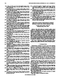
4. Results Figure 1 and 2 show optimum speed profile and control profile for a trip of 120 sec and 2 km. There are no speed limits nor elevations during the trip. The train in this example has the mass of 100 tons with nine notches for acceleration and nine notches for deceleration plus a coasting notch (i.e. no tractive effort) which means 10 control variables in total (Trip 1).
Proceedings of the 56th SIMS October 07-09, 2015, Linköping, Sweden
DOI 10.3384/ecp15119377
Session 10B: Session B
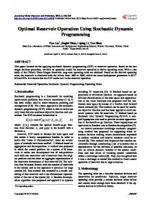
Figure 1. Optimum speed profile for a trip of 2km and 120 sec for a train with 9 notches for acceleration and 9 notches for brake (Trip 1) Figure 3. Optimum speed profile for a trip of 2km and 220 sec for a train with 9 notches for acceleration and 9 notches for brake (Trip 2)
Figure 2. Optimum control profile for a trip of 2km and 120 sec for a train with 9 notches for acceleration and 9 notches for brake (Trip 2)
The same train is run on the same track with elevations and speed limits. Trip time in this case is 170 sec (Trip 2). The results are available in figure 3 and 4. The dotted line represents the speed limit and the dashed line represents the elevations.
DOI 10.3384/ecp15119377
Figure 4. Optimum control profile for a trip of 2km and 220 sec for a train with 9 notches for acceleration and 9 notches for brake (Trip 2)
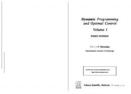
This approach can also be used for the trains with continuous tractive effort. In that case however, high discretization on the control variable is needed. Figures 5 and 6 show optimum speed profile and tractive effort profile for a train with continuous tractive effort on a level track with no elevation. Trip time is assumed to be 120 sec and track length is 2 km (Trip 3). The tractive effort is discretized in 120 steps.
Proceedings of the 56th SIMS October 07-09, 2015, Linköping, Sweden
379
Optimal Control of an EMU Using Dynamic Programming and Tractive Effort as the Control Variable
Figure 5. Optimum speed profile for a trip of 2km and 120 sec for a train with 60 notches for acceleration and 60 notches for brake (Trip 3)
Figure 7. Optimum speed profile for a trip of 2km and 230 sec for a train with 60 notches for acceleration and 60 notches for brake (Trip 4)
Figure 6. Optimum control profile for a trip of 2km and 120 sec for a train with 60 notches for acceleration and 60 notches for brake (Trip 3)
Figure 8. Optimum control profile for a trip of 2km and 230 sec for a train with 60 notches for acceleration and 60 notches for brake (Trip 4)
The same train is run on the same track with elevations and speed limits. The trip time in this case is 230 sec (Trip 4). The results are available in figure 7 and 8.
Table 1 shows the train configuration and the track data for each trip. Table 1. Train data and track data for the 4 trips. Trip distance is 2 km for all trips
Trip 1 Trip 2 Trip 3 Trip 4 380
Number of control variables 19
Trip time [sec] 120
Speed limits
Elevations
no
No
19
170
yes
Yes
120
120
no
No
120
230
yes
yes
Proceedings of the 56th SIMS October 07-09, 2015, Linköping, Sweden
DOI 10.3384/ecp15119377
Session 10B: Session B
the Root-Mean-Square error of the total errors for the 4 trips presented in the results section.
5. Discussion In this section the application and the accuracy of the approach is discussed and a short comparison is made between the two approaches (i.e. the one presented in (Ghaviha, Bohlin et al. 2014) and the approach presented here). The comparison is made with regard to two criteria of accuracy and ease of application.
5.1. Application The approaches presented here and in (Ghaviha, Bohlin et al. 2014) are developed to be a base for a driver advisory system, which is a system that gives instructions to driver on how to drive a train with the aim of minimizing the energy consumption. Traction motor in some trains provide a certain number of notches for acceleration and braking, in other words the tractive effort is discrete, whereas in other trains the tractive effort is continuous which is like the gas pedal in cars. When it comes to controlling a train, driver has the direct control on the tractive effort of the train. Therefore the best way to design a driver advisory system is to give instructions in the form of optimal tractive effort. This would be easy in trains with different notches for the tractive effort and therefore the approach with the tractive effort as the control variable suits best for these kinds of trains. In the trains with the continuous tractive effort however, as the driver has access to continuous tractive effort, following the instructions in the form of the tractive effort would be problematic for the driver. In this case the optimum velocity sounds like a more suitable form of instruction. Although it is possible to give instruction in the form of the optimum velocity using the approach with the tractive effort as control variable, it is better to use the approach with the velocity as the control variable due to accuracy issues, which will be discussed in the next section, Accuracy. 5.2. Accuracy As mentioned in the Approach section, � � and � � should be rounded to the closest distance and velocity step. As the result the model has an inaccuracy regarding the velocity and the distance calculations. To study these, two following errors are introduced:
�
��
= ��� − ��� = ��� − ���
(12) (13)
Where � is the difference between the real velocity (��� ) and the rounded velocity (��� ) in time step � and �� is the difference between the real distance (��� ) and the rounded distance (��� ) in time step �. Table 1 shows DOI 10.3384/ecp15119377
Table 2. RMSE of distance and velocity variables for the four trips
RMSE for �[km/h]
Trip 1
RMSE for �[m]
Trip 2
1.008387
Trip 3
1.994318
0.29593
Trip 4
2.157717
0.284606
1.988579
0.148767 0.112893
As mentioned before, trip 3 and 4 are meant for the train with continuous tractive effort. A solution can also be generated using the previous approach presented in (Ghaviha, Bohlin et al. 2014). The same error is also calculated for that solution and can be seen in table 3. Note that since the velocity in the next time step is assumed to be the control variable in the previous approach, there would be no error for the velocity. This is because of the fact that in the previous approach, the velocity is selected, rather than being calculated and used as state variable (Ghaviha, Bohlin et al. 2014). Moreover for the sake of comparison, the same time, distance and velocity discretization is used for both approaches. Table 3. RMSE of distance for the solution of trip 3 and 4 using the previous approach
Trip 3 Trip 4
RMSE for �[m] 2.090435 2.480182
As it can be seen the errors are negligible considering the fact that the length of the track is 2 km and the maximum train speed is 80 km per hours. Both approaches also give almost the same RMSE for trip 3 and 4. However, when it comes to the comparison of the two approaches, the one presented in (Ghaviha, Bohlin et al. 2014) is more promising, as the distance is the only variable which is estimated in that approach.
6. Conclusion A train model and an approach is presented in this paper for the optimal control of an electric train based on discrete dynamic programming. The problem was previously solved with the velocity as the control variable. In the approach presented here tractive effort is used as the control variable. This approach is most
Proceedings of the 56th SIMS October 07-09, 2015, Linköping, Sweden
381
Optimal Control of an EMU Using Dynamic Programming and Tractive Effort as the Control Variable
suitable for the trains with different notches for the acceleration and braking (discrete tractive effort) as the control variable can be adjusted according to the number of notches available in the train. However for the trains with continuous control on the tractive effort, the approach presented in (Ghaviha, Bohlin et al. 2014) is more suitable as it has higher accuracy compared to the approach presented in this paper. It is to be mentioned that a more thorough study is needed to compare the two approaches regarding the application and instruction issues, as more data and information is needed regarding the drivers’ behavior when using a driver advisory system.
Acknowledgements This research is funded by VINNOVA, grant number 2014-04319. The authors would like to thank Christer Holmberg from Bombardier Transportation Västerås for the help and support with the data and information on electric trains and propulsion system.
References Chang, C. S. and S. S. Sim (1997). "Optimising train movements through coast control using genetic algorithms." Electric Power Applications, IEE Proceedings - 144(1): 65-73. Colak, K., D. Czarkowski, et al. (2012). Energy minimization for catenary-free mass transit systems using Particle Swarm Optimization. Electrical Systems for Aircraft, Railway and Ship Propulsion (ESARS), 2012. Franke, R., P. Terwiesch, et al. (2000). An algorithm for the optimal control of the driving of trains. Decision and Control, 2000. Proceedings of the 39th IEEE Conference on. Ghaviha, N., M. Bohlin, et al. (2014). An Algorithm For Optimal Control of an Electric Multiple Unit. Proceedings from The 55th Conference on Simulation and Modelling (SIMS 55),21-22 October, 2014. Aalborg, Denmark :. Linköping, Linköping University Electronic Press. Ghaviha, N., M. Bohlin, et al. (2015). "Optimal Control of an EMU Using Dynamic Programming." Energy Procedia 75: 1913-1919. Howlett, P. (2000). "The Optimal Control of a Train." Annals of Operations Research 98(1-4): 65-87. Ichikawa, K. (1968). "Application of Optimization Theory for Bounded State Variable Problems to the Operation of Train." Bulletin of JSME 11(47): 857-865. Ko, H., T. Koseki, et al. (2004). "Application of dynamic programming to optimization of running profile of a train." Computers in railways IX: 103-112. Liu, R. and I. M. Golovitcher (2003). "Energy-efficient operation of rail vehicles." Transportation Research Part A: Policy and Practice 37(10): 917-932. Miyatake, M. and H. Haga (2010). Optimization of speed profile and quick charging of a catenary free train with onboard energy storage. Electrical Systems for Aircraft, Railway and Ship Propulsion (ESARS), 2010.
382
Miyatake, M., H. Haga, et al. (2009). Optimal speed control of a train with On-board energy storage for minimum energy consumption in catenary free operation. Power Electronics and Applications, 2009. EPE '09. 13th European Conference on. Miyatake, M. and H. Ko (2007). Numerical analyses of minimum energy operation of multiple trains under DC power feeding circuit. Power Electronics and Applications, 2007 European Conference on. Miyatake, M. and H. Ko (2007). Numerical Optimization of Speed Profiles of Inverter Trains Considering DC Feeding Circuit. Power Conversion Conference - Nagoya, 2007. PCC '07. Miyatake, M. and H. Ko (2010). "Optimization of Train Speed Profile for Minimum Energy Consumption." IEEJ Transactions on Electrical and Electronic Engineering 5(3): 263-269. Miyatake, M. and K. Matsuda (2008). Optimal speed and charge/discharge control of a train with onboard energy storage devices for minimum energy operation. Power Electronics, Electrical Drives, Automation and Motion, 2008. SPEEDAM 2008. International Symposium on. Miyatake, M. and K. Matsuda (2009). "Energy Saving Speed and Charge/Discharge Control of a Railway Vehicle with On-board Energy Storage by Means of an Optimization Model." IEEJ Transactions on Electrical and Electronic Engineering 4(6): 771-778. Panou, K., P. Tzieropoulos, et al. (2013). "Railway driver advice systems: Evaluation of methods, tools and systems." Journal of Rail Transport Planning & Management 3(4): 150-162. Shuai, S., L. Xiang, et al. (2013). "A Subway Train Timetable Optimization Approach Based on EnergyEfficient Operation Strategy." Intelligent Transportation Systems, IEEE Transactions on 14(2): 883-893. Wong *, K. K. and T. K. Ho (2004). "Dynamic coast control of train movement with genetic algorithm." International Journal of Systems Science 35(13-14): 835-846. Wong, K. K. and T. K. Ho (2004). "Coast control for mass rapid transit railways with searching methods." Electric Power Applications, IEE Proceedings - 151(3): 365-376. Yang, L., K. Li, et al. (2012). "Optimizing trains movement on a railway network." Omega 40(5): 619-633. Yasunobu, S., S. Miyamoto, et al. (1983). "A Fuzzy Control for Train Automatic Stop Control." Transactions of the Society of Instrument and Control Engineers 19(11): 873880.
Proceedings of the 56th SIMS October 07-09, 2015, Linköping, Sweden
DOI 10.3384/ecp15119377


![[PDF] Dynamic Programming and Optimal Control (2 ... - Google Sites](https://m.moam.info/img/260x300/pdf-dynamic-programming-and-optimal-control-2-goog_64780723097c47a9708c5ee1.jpg)
![[PDF] Download Dynamic Programming and Optimal Control: 1 Full ...](https://m.moam.info/img/260x300/pdf-download-dynamic-programming-and-optimal-contr_6478b06c097c474d228d6e7b.jpg)
![[PDF] Dynamic Programming and Optimal Control, Vol ... - Google Sites](https://m.moam.info/img/260x300/pdf-dynamic-programming-and-optimal-control-vol-go_64773a5f097c4744708b79be.jpg)


