Mar 12, 2015 - D2D users may experience high data rate and low transmission delay due ..... Table I lists all the parameters and variables used in the problem ...
1
Optimal Resource Allocation in Multicast Device-to-Device Communications Underlaying
arXiv:1503.03576v1 [cs.NI] 12 Mar 2015
LTE Networks Hadi Meshgi1 , Dongmei Zhao1 and Rong Zheng2 1
Department of Electrical and Computer Engineering, McMaster University 2
Department of Computing and Software, McMaster University
Abstract In this paper, we present a framework for resource allocations for multicast device-to-device (D2D) communications underlaying a cellular network. The objective is to maximize the sum throughput of active cellular users (CUs) and feasible D2D groups in a cell, while meeting a certain signal-to-interferenceplus-noise ratio (SINR) constraint for both the CUs and D2D groups. We formulate the problem of power and channel allocation as a mixed integer nonlinear programming (MINLP) problem where one D2D group can reuse the channels of multiple CUs and the channel of each CU can be reused by multiple D2D groups. Distinct from existing approaches in the literature, our formulation and solution methods provide an effective and flexible means to utilize radio resources in cellular networks and share them with multicast groups without causing harmful interference to each other. A variant of the generalized bender decomposition (GBD) is applied to optimally solve the MINLP problem. A greedy algorithm and a low-complexity heuristic solution are then devised. The performance of all schemes is evaluated through extensive simulations. Numerical results demonstrate that the proposed greedy algorithm can achieve closeto-optimal performance, and the heuristic algorithm provides good performance, though inferior than that of the greedy, with much lower complexity.
I. I NTRODUCTION Device-to-Device (D2D) communication is a technology component for Long Term EvolutionAdvanced (LTE-A) of the Third Generation Partnership Project (3GPP) [1]. In D2D communication,
2
cellular users (CUs) in close proximity can exchange information over a direct link rather than transmitting and receiving signals through a cellular base station (BS). D2D users communicate directly while remaining controlled under the BS. Compared to routing through a BS, CUs at close proximity can save energy and resources when communicating directly with each other. Moreover, D2D users may experience high data rate and low transmission delay due to the short-range direct communication [2]. Reducing the network load by offloading cellular traffic from the BS and other network components to a direct path between users is another benefit of D2D communication reduce the network load and increase its effective capacity. Other benefits and usage cases are discussed in [3]. The majority of the literature in D2D communications uses the cellular spectrum for both D2D and cellular communications,also known as in-band D2D [4]. Generally, in-band D2D falls in two categories, underlay and overlay [5]. Underlay in-band D2D can improve the spectrum efficiency of cellular networks by reusing cellular resources. Its main drawback lies in the interference caused by D2D users to cellular communications. Thus, efficient interference management and resource allocation are required to guarantee a target performance level of the cellular communication [6], [7]. In order to avoid this interference issue, it has also been proposed to dedicate part of the cellular resources to D2D communications in overlay in-band D2D. In this case, designing a resource allocation scheme is crucial to maximize the utilization of dedicated cellular resources [8]. Other works consider out-of-band instead of in-band D2D communications so that the cellular spectrum would not be affected by D2D communications [9]. Out-of-band D2D communication faces challenges in coordinating the communication over two different bands because usually D2D communication happens on a second radio interface (e.g., WiFi Direct and Bluetooth) [10]. Most of the work in D2D resource allocation targets the unicast scenario where a single or multiple D2D pairs reuse the resources of CUs. In [4], the authors consider throughput maximization where by allowing D2D communication to underlay the cellular network, the overall throughput in the network can increase compared to a case where all D2D traffic is relayed by the cellular network. Some other work such as [10], [11] consider D2D communication reliability while guaranteeing a certain level of SINR or outage probability. The works in [12], [13], [14] consider both throughput and reliability simultaneously. In [12], throughput is maximized for a network with a single D2D pair and a single CU subject to spectral efficiency restrictions and energy constraints. There are
3
few works for scenarios with multiple D2D users and CUs. For example, the quality-of-service (QoS) requirements for both CUs and D2D users have been investigated in [13] and [14]. In [13], a heuristic algorithm has been proposed to solve the MINLP resource allocation problem that aims to decrease interference to the cellular network and maximize the total throughput. The authors in [14] present a framework of resource allocation for D2D communications underlaying cellular networks to maximize the overall network throughput of existing CUs and admissible D2D pairs while guaranteeing the QoS requirements for both CUs and D2D pairs. A scheme based on maximum weight bipartite matching is proposed to determine a specific CU partner for each admissible D2D pair. Multicast D2D transmissions, where the same packets for a UE are sent to multiple receivers, are important for scenarios such as multimedia streaming, device discovery, and public safety. Specially, D2D multicast communications are required features in public safety services like police, fire and ambulance [1]. Compared to communicating with each receiver separately in unicast D2D, multicast D2D transmission reduces overhead and saves resources. However, unlike the more commonly studied unicast D2D (see e.g. [12] [14]), multicast D2D has its own challenges. Within a multicast group, the data rates attainable at different receivers are different because of the diverse link conditions between each receiver and the transmitter. A common approach is to transmit at the lowest rate of all users within a group determined by the user with the worst channel condition. This assures that multicast services can be provided to all users. On the one hand, as all multicast users within a group receive the same data rate, the total sum rate grows with the number of active users of the group. On the other hand, the lowest transmission rate typically decreases as the number of users increases since it is based on the user with the Least Channel Gain (LCG) [15]. As discussed in [15] there are lots of works in multicast scheduling and resource allocation for OFDMA-based systems. They can be broadly classified into two types: single-rate and multi-rate transmissions. In single-rate broadcast, the BS transmits to all users in each multicast group at the same rate irrespective of their non-uniform achievable capacities, whereas in multirate broadcast, the BS transmits to each user in each multicast group at different rates based on what each user can handle. All of the works mentioned in [15] targeted cellular networks where the multicast transmitter is the BS. However, in multicast D2D, UEs are multicast transmitters and the QoS requirements for both the D2D links and the cellular links should be satisfied.
4
The problem of resource management for D2D multicast communication was first addressed in our previous work [16]. In [16] we formulate the power and channel allocation problem for D2D multicast communication for a special case where each D2D group can reuse the channel of one CU and the channel of each CU can be reused by at most one D2D group. The optimal solution is found using maximum weight bipartite matching algorithm and a low-complexity heuristic algorithm is also proposed. Moreover, we adapt the heuristic scheme in [13] for multicast D2D and compare it against our scheme and show that our proposed heuristic has a superior performance. In this paper, we consider multicast D2D communications underlaying cellular networks and present a joint power and channel allocation scheme to maximize the total throughput of all CUs and D2D groups within a cell. We formulate the general problem of power and channel allocation as an MINLP where one D2D group can reuse the channels of multiple CUs and the channel of each CU can be reused by multiple D2D groups. To guarantee the QoS requirements for both CUs and D2D groups, a minimum SINR constraint is imposed. A variant of the generalized bender decomposition (GBD) is applied to optimally solve the MINLP problem. We further propose an exact solution to a special case of the general problem. Specifically, inspired by the work in [14], we use the maximum weight bipartite matching algorithm for the case where each D2D group can reuse the channel of at most one CU and each CU can share their resources with at most one D2D group. Next, we propose a greedy algorithm with a somewhat high complexity but very close-to-optimal performance. A low-complexity heuristic solution is then devised which trades computation complexity with performance. This heuristic algorithm is an extension to the heuristic algorithm presented [16] for the general scenario. The remainder of the paper is organized as follows. In Section II, the system model is described and the problem of power and channel allocation for underlay multicast D2D communication is formulated. Section III describes the generalized bender decomposition method to solve the general problem. The matching-based optimal resource allocation for one special case is presented in Section IV, and the greedy and the heuristic algorithms are presented in Section V. Numerical results are demonstrated in Section VI, and Section VII concludes the paper.
5
II. S YSTEM M ODEL
AND
P ROBLEM F ORMULATION
We study resource allocation for multicast D2D communcations underlaying uplink (UL) transmissions in LTE networks. UL resource sharing is considered since reusing downlink resources is more difficult and less effective than reusing uplink resources in the worst case of a fully loaded cellular network, as demonstrated in [17]. Consider K groups of multicast D2D users coexisting with M CUs. We assume a fully loaded cellular network scenario. That is, there are M channels, each occupied by one CU. We use m ∈ M = {1, 2, . . . , M} to index both the mth CU and the channel it occupies, and k ∈ K = {1, 2, . . . , K} to index the kth D2D group. We consider a single cell scenario and assume that advanced intercell interference mitigation is applied on top of our scheme. Within a D2D group, there is only one user that multicasts messages to the remaining users. Each D2D user only belongs to one D2D group. We use Dk to represent the set of D2D receivers in the kth multicast group, and |Dk | is the total number of receivers in the group. As a special case, when |Dk | = 1, the scenario becomes unicast. Define a set of binary variables ykm with ykm = 1 if the kth D2D group reuses channel m, and ykm = 0 otherwise. In the general case, each D2D group splits its multicast traffic among maximally C1 channels where C1 ≤ M, and each channel can be reused by at most C2 D2D groups where C2 ≤ K. That is, M X
yk,m ≤ C1 , ∀k ∈ K
(1)
yk,m ≤ C2 , ∀m ∈ M.
(2)
m=1 K X k=1
The channel quality of receiver d in the kth D2D group at channel m is given by D2D βk,m,d
GD2D k,m,d P , = C2D D2D Cell Pnoise + Pm Gk,m,d + k′ 6=k PkD2D ′ ,m Gk,k ′ ,d
(3)
D2D where Pnoise is the aggregate power of background noise, Gk,m,d is the link gain to D2D receiver
d from the D2D transmitter in group k at channel m, GC2D k,m,d is the link gain from CU m to D2D D2D receiver d in group k, PmCell is the transmission power of CU m, Pk,m is the transmission power D2D of the kth D2D group transmitter at channel m, and Gk,k ′ ,d the link gain from the transmitter at
D2D group k ′ to receiver d at D2D group k.
6
For the kth D2D group, its transmission condition in channel m is determined by the receiver with the worst condition. Define D2D D2D βk,m = min βk,m,d . d∈Dk
(4)
Then, the normalized transmission rate (bit/s/Hz) of the kth D2D group is given by rkD2D
=
M X
D2D D2D yk,m log2 (1 + Pk,m βk,m ).
(5)
m=1
The aggregate transmission rate of the kth D2D group is given by RkD2D = |Dk |rkD2D .
(6)
For CU m, its channel quality is given by Cell βm =
GCell m , PK D2D D2C Pnoise + k=1 yk,mPk,m Gk,m
(7)
D2C where GCell is the link gain of CU m to the cellular base station, and Gk,m is the link gain m
from the kth D2D transmitter to the cellular base station at channel m. Therefore, the normalized transmission rate for CU m is Cell Cell Rm = log2 (1 + PmCell βm ).
(8)
A threshold is set for the SINR of each D2D group and CU transmission. For the kth D2D group, D2D D2D D2D Pk,m βk,m ≥ yk,mγth ,
(9)
and for CU m, Cell Cell PmCell βm ≥ γth .
(10)
Given these SINR threshold constraints, we can approximate the capacity in higher SINR cases by removing the term “1” from the logarithm functions in both (5) and (8). The maximum power constraints for CUs and D2D groups, respectively, are given by Cell PmCell ≤ Pmax , ∀m ∈ M,
and
M X
m=1
D2D D2D Pk,m ≤ Pmax , ∀k ∈ K.
(11)
(12)
7
The objective is to maximize the aggregate data transmission rate of all the D2D groups and CUs. Combining (1) – (12), we formulate the joint power control and channel allocation problem to maximize the sum throughput of multicast D2D groups and cellular users as follows, ! M K X X Cell Rm P1. max RkD2D + s.t.
RkD2D
=
(13)
m=1
k=1
M X
D2D D2D yk,m |Dk | log2 (Pk,m βk,m ), ∀k ∈ K, m ∈ M,
(14)
m=1 Cell Rm
=
D2D βk,m ≤
K X
� Cell , ∀m ∈ M, log2 PmCell βm
k=1 D2D βk,m,d ,
∀k ∈ K, m ∈ M, d ∈ Dk ,
yk,m ∈ {0, 1}, ∀k ∈ K, m ∈ M,
(15) (16) (17)
Constraints (1), (2), (7), (9), (10), (11), (12). Table I lists all the parameters and variables used in the problem formulation. Clearly, P1 is a Mixed Integer Nonlinear Programming (MINLP) problem. In general, MINLP problems are NP-hard and thus no efficient polynomial-time solutions exist. In the general case, when C1 and C2 are arbitrary values, we will use GBD [18] to solve the problem in the next section. Based on the values of C1 and C2 , several special cases exist. For example, when C1 = 1 and C2 = 1, each D2D group can reuse the channels of at most one CU and each CU can share their channels with at most one D2D group. Another special case of interest is when C1 = 1. In this case, to increase the spectrum utilization, we allow each D2D group to reuse the resources of multiple CUs, but each CU cannot share its resource with more than one D2D group. Here, there is no interference between D2D groups and this setting is useful when the number of D2D groups is much less than the number of CUs. All the special cases can be resolved via GBD. However, it turns out that polynomial algorithm can be devised when C1 = 1 and C2 = 1 as will be discussed in Section IV. III. G ENERALIZED B ENDER D ECOMPOSITION The MINLP problem in P1 has the special property that when the binary variables (yk,m’s) are D2D fixed, the problem becomes a geometric programming problem with continuous variables (Pk,m ’s
8
TABLE I: Table of notations Notation
Description
M
Set of cellular users (CU)
K
Set of D2D groups
Dk
Set of receivers in kth D2D group
A
Set of admissible or successful D2D groups
yk,m
Binary variable, =1 if kth D2D group reuses CU m’s channel, and =0 otherwise
C1
Maximum number of channels to be reused by each D2D group
C2
Maximum number of D2D groups sharing each CU channel
Pnoise
Aggregate power of background noise
GD2D k,m,d
Link gain to D2D receiver d from the D2D transmitter in group k at channel m
GC2D k,m,d
Link gain from CU m to D2D receiver d in group k
GD2D k,k′ ,d
Link gain from the transmitter at D2D group k′ to receiver d at D2D group k
GCell m
Link gain of CU m to the cellular base station
GD2C k,m
Link gain from the kth D2D transmitter to the cellular base station at channel m
D2D Pk,m
Transmission power of the kth D2D group transmitter at channel m
Cell Pm
Transmission power of CU m
D2D βk,m,d
Channel quality of receiver d in the kth D2D group at channel m
Cell βm
Channel quality of CU m
RkD2D
Normalized transmission rate of the kth D2D group
Cell Rm
Normalized transmission rate for CU m
R
sum
The summation of D2D and cellular throughput
D2D γth
SINR threshold for all D2D groups
Cell γth
SINR threshold for all CUs
fi (|DK |)
The complexity of solving problem Pi
and PmCell ’s), which can be transformed to a convex problem. This allows us to use GBD [18] to solve the problem efficiently with proper transformation. D2D Cell D2D Cell Let X = [Pk,m , PmCell , RkD2D , Rm , βk,m , βm , k ∈ K, m ∈ M] represent the set of all con-
tinuous variables and Y = [yk,m , k ∈ K, m ∈ M] represent the binary variables. We modify the constraints in problem P1 to separate binary variables ykm from the continuous variables in X and make the problem linear in terms of yk,m ’s when the continuous variables are fixed. Problem P1 can be transformed as P2. f (X, Y) = max
K X k=1
RkD2D
+
M X
m=1
Cell Rm
!
(18)
9
s.t.
RkD2D
≤
M X
D2D D2D |Dk | log2 (Pk,m βk,m ) + C(1 − yk,m), ∀k ∈ K, m ∈ M,
(19)
m=1
RkD2D ≤ Cyk,m, ∀k ∈ K, m ∈ M, Cell Rm
≤
K X k=1
Cell βm
(20)
� Cell , ∀m ∈ M, log2 PmCell βm
(21)
GCell m , ∀m ∈ M, ≤ PK D2D D2C Gk,m Pnoise + k=1 Pk,m
D2D ≤ βk,m D2D Pk,m D2D Pmax
(22)
GD2D k,m,d P , ∀k ∈ K, m ∈ M, d ∈ Dk , (23) D2D D2D Pnoise + PmCell GC2D k,m,d + k ′ 6=k Pk ′ ,m Gk,k ′ ,d
D2D ≤ yk,m + ǫ ≤ CPk,m , ∀k ∈ K, m ∈ M,
(24)
Constraints (1), (2), (7), (9), (10), (11), (12), (17). where C is a very large number and ǫ > 0 is a very small number. The basic idea of GBD is to decompose the original MINLP problem into a primal problem and a master problem, and solve them iteratively. The primal problem corresponds to the original problem with fixed binary variables. Solving this problem provides the information about the lower bound and the Lagrange multipliers corresponding to the constraints. The master problem is derived through nonlinear duality theory using the Lagrange multipliers obtained from the primal problem. The solution to the master problem gives the information about the upper bound as well as the binary variables that can be used in the primal problem in next iteration. When the upper bound meets the lower bound, the iterative process converges. A. Primal problem The primal problem results from fixing the yk,m variables to a particular 0-1 combination denoted (i)
by yk,m , where i stands for the iteration counter. The formulation for the primal problem at iteration i is given by P3. f (X, Y (i)) = max
K X k=1
s.t. RkD2D ≤
M X
RkD2D +
M X
m=1
Cell Rm
!
(25) (i)
D2D D2D |Dk | log2 (Pk,m βk,m ) + C(1 − yk,m), ∀k ∈ K, m ∈ M,
(26)
m=1 (i)
RkD2D ≤ Cyk,m , ∀k ∈ K, m ∈ M,
(27)
10
Cell Rm
≤
K X k=1
Cell βm ≤
D2D βk,m ≤ D2D Pk,m D2D Pmax
� Cell log2 PmCell βm , ∀m ∈ M,
(28)
GCell m , ∀m ∈ M, PK D2D D2C Pnoise + k=1 Pk,m Gk,m
(29)
GD2D k,m,d P , ∀k ∈ K, m ∈ M, d ∈ Dk , (30) D2D D2D Pnoise + PmCell GC2D k,m,d + k ′ 6=k Pk ′ ,m Gk,k ′ ,d (i)
D2D ≤ yk,m + ǫ ≤ CPk,m , ∀k ∈ K, m ∈ M,
(31)
(i)
D2D D2D PkD2D βk,m ≥ yk,m γth , ∀k ∈ K, m ∈ M,
(32)
Constraints (10), (11), (12), (22), (23).
Since the optimal solution to this problem is also a feasible solution to problem P1, the optimal value f (X∗ , Y (i) ) provides a lower bound to the original problem. In general, not all choices of binary variables lead to a feasible primal problem. Therefore, for a given choice of yk,m’s, there are two cases for primal problem P3: feasible problem and infeasible problem. In the following, we consider each of these cases. •
Feasible Primal: If the primal problem at iteration i is feasible, then its solution provides information on the transmission power of D2D and cellular transmitters, f (X∗, Y (i) ), and the optimal multiplier vectors, λkq , q = 1, 2, . . . , Q for the Q inequality constraints in Problem P3. Subsequently, using this information we can formulate the Lagrange function for all inequality constraints Gq (X, Y (i) ) ≤ 0 for q = 1, 2, . . . , Q as (i)
(i)
(i)
L(X, Y , λ ) = f (X, Y ) +
Q X
(i) λ(i) q Gq (X, Y ),
(33)
q=1
(i)
where λ(i) = [λq , q = 1, 2, . . . , Q]. •
Infeasible Primal: If the primal problem is infeasible, to identify a feasible point we can formulate an l1 -minimization problem as P3.1. min
Q X
αq
(34)
q=1
s.t.
Gq (X, Y (i)) ≤ αq , q = 1, 2, ..., Q,
(35)
11
αq ≥ 0, q = 1, 2, ..., Q.
(36)
PQ
αq = 0, then P3 is feasible. Otherwise, the solution to this feasibility ¯ (i) problem (FP) provides information on the Lagrange multipliers, which are denoted as λ q ; the Note that if
q=1
Lagrange function resulting from the feasibility problem at iteration i can be defined as ¯ (i) ) = ¯ L(X, Y (i), λ
Q X
¯ (i) (Gq (X, Y (i)) − αq ). λ q
(37)
q=1
B. Master Problem The master problem is derived from the non-linear duality theory [18]. P4. max η
(38)
s.t. η ≤ sup L(X, Y (i), λ(i) ), ∀λ(i) ≥ 0,
(39)
¯ (i) ) ≤ 0, ∀λ ¯ (i) ∈ Λ, ¯ inf L(X, Y (i), λ
(40)
Constraints (1), (2), (17),
(41)
Y(i)
X
X
where ¯ q ≥ 0, Λ = {λ
Q X
¯ q = 1}. λ
(42)
q=1
The master problem P4 is similar to the original problem P2, but has two inner optimization problems which need to be considered for all λ and λ obtained from the primal problem in every iteration. Therefore, it has a very large number of constraints. Because of the separability of binary variables Y and continuous variables X, and the linearity with regard to Y, we can adopt Variant 2 of GBD (V2-GBD) in [18]. It is proven in [18] that under the conditions for V2-GBD, the Lagrange function evaluated at the solution of the corresponding primal is a valid under-estimator of the inner optimization problem in P4. Therefore, the relaxed master problem can be formulated as,
P5. max η
(43)
s.t. η ≤ L(X, Y (i) , λ(i) ), ∀λ(i) ≥ 0,
(44)
Y(i)
12
¯ (i) ) ≤ 0, ∀λ ¯ (i) ∈ Λ, ¯ L(X, Y (i) , λ
(45)
Constraints (1), (2), (17).
(46)
The relaxed problem provides an upper bound to the master problem and can be used to generate the primal problem in the next iteration.The same procedure is then repeated until convergence. Over the iterations, the sequence of upper bounds are nonincreasing and the set of lower bounds are nondecreasing. The two sequences are proven to converge and the algorithm will stop at the optimal solution within a finite number of iterations [19]. Algorithm 1 summarizes the GBD procedure. Algorithm 1 GBD Algorithm 1: First iteration, i = 1 2:
Select an initial value for Y (i) , which makes the primal problem feasible.
3:
Solve the primal problem in P3 and obtain the Lagrange function
4:
UBD (i) = ∞, LBD (i) = 0
5:
while UBD (i) − LBD (i) > 0 do
6:
i=i+1
7:
Solve the relaxed master problem P5 to optain η ∗ and Y ∗
8:
Set UBD (i) = η ∗
9:
Solve the primal problem P3 with fixed Y (i) = Y ∗
10:
if the primal problem is feasible then
11:
Obtain optimal solution X∗ and the Lagrange function L(X, Y (i) , λ(i) )
12:
Set LBD (i) = max(LBD (i−1) , f (i) (X∗ , Y (i) ))
13: 14:
else Solve the feasibility-check problem P3.1 to obtain the optimal solution X∗ and the ¯ (i) ) ¯ Lagrange function L(X, Y (i), λ
15:
end if
16:
end while
13
IV. M ATCHING - BASED O PTIMAL R ESOURCE A LLOCATION In this section, we consider the MINLP problem in P1 for the special case C1 = 1 and C2 = 1. This case can be cast as a bipartite matching problem and thus can be solved polynomially. To formulate the bipartite problem, we divide P1 into two subproblems. In the first step, for each D2D group k and each CU m, we find their transmission power so that the sum throughput of the D2D group and the CU is maximized. If this problem is feasible, D2D group k is allowed to reuse the channel of CU m and is marked as a candidate partner in the second step; otherwise group k is excluded from the list of feasible partners. The second step is then to find the best CU partner for each D2D group among all feasible candidates so that the total throughput of all D2D groups and CUs is maximized. 1) Feasibility check and power allocation: In order to determine whether D2D group k can reuse channel m and to find the transmission power of the feasible D2D group and CU,we have problem P6 as follows: D2D Cell P6. max Rk,m + Rk,m
�
D2D D2D D2D s.t. Rk,m = |Dk | log2 (Pk,m βk,m ), � Cell Cell , Rk,m = log2 PmCell βm
(47) (48) (49)
D2D D2D D2D Pk,m βk,m ≥ γth ,
(50)
Cell Cell PmCell βm ≥ γth ,
(51)
Cell βm =
D2D βk,m ≤
GCell m , D2D D2C Gk,m Pnoise + Pk,m
(52)
GD2D k,m,d , ∀d ∈ Dk Pnoise + PmCell GC2D k,m,d
(53)
Cell PmCell ≤ Pmax , M X
D2D D2D Pk,m ≤ Pmax .
(54) (55)
m=1
P6 is a reduced version of P1 by limiting it to only one D2D group and one CU with the objective of maximizing their sum throughput. Clearly, P6 is a geometric programming problem and can be transformed to a convex optimization problem using geometric programming techniques [20]. We
14
solve problem P6 for all k and m pairs. Define a candidate channel set Ck for D2D group k. If the problem is feasible, D2D group k is admissible to channel m (i.e., eligible to use channel m), then m is added to Ck . For m ∈ Ck , denote the optimal throughput for the kth D2D transmitter and the mth ∗D2D ∗Cell sum ∗D2D ∗Cell CU as Rk,m and Rk,m , respectively, and the optimal sum throughput as Rk,m = Rk,m + Rk,m . � Cell Cell � Gm sum ∗Cell ∗D2D ∗Cell , and thus Rk,m = Rk,m . For m ∈ / Ck , we set Rk,m = 0, Rk,m = log2 Pmax Pnoise
2) Maximizing total throughput: Given the maximum achievable throughput for each D2D group
when reusing each cellular channel, to find the optimal channel allocation that maximizes the total throughput we have,
P7. max yk,m
s.t.
K X
K X M X
sum yk,mRk,m
(56)
k=1 m=1
yk,m ≤ 1, ∀m ∈ M
(57)
yk,m ≤ 1, ∀k ∈ K
(58)
k=1
M X
m=1
yk,m ∈ {0, 1}, ∀k ∈ K, m ∈ M.
(59)
P7 is in effect the maximum weight bipartite matching problem, where the D2D groups and the cellular channels are two groups of vertices in the bipartite graph, and the edge connecting D2D sum group k and channel m has a weight Rk,m . The Hungarian algorithm [21] can be used to solve
the bipartite matching problem in polynomial time. To determine the computational complexity, consider M ≥ K and the complexity of solving P6 is a function of the size of each D2D group, i.e. f6 (|DK |). Therefore, the time complexity of the matching-based optimal resource allocation is O(M × K × f6 (|DK |)) + O(M 3 ) , where the first and second terms correspond to the computation time in the first and second steps, respectively. V. G REEDY
AND
H EURISTIC C HANNEL
ALLOCATION ALGORITHMS
The MINLP problem in P1 is an NP-hard problem and the computation complexity is exponential in the worst case. In other words, GBD may converge in an exponential number of iterations. In this section we first propose a greedy algorithm and then a heuristic solution to the general MINLP problem in P1.
15
Algorithm 2 Greedy algorithm 1: M: Set of cellular users 2:
K: Set of all D2D groups
3:
ek,m = 1, ∀k ∈ K, m ∈ M
4:
Y = [yk,m| yk,m = 0, ∀k ∈ K, m ∈ M]
5:
S =∅
6:
while
7: 8: 9:
PK PM k=1
m=1 ek,m
≥ 1 do
E = [ek,m | ek,m = 1, ∀k ∈ K, m ∈ M] � Cell Cell � PM P Gm′ sum , ∀k ∈ K, m ∈ M Tk,m = m′ =1 log2 max Pnoise
for each ek,m ∈ E do
10:
yk,m = 1
11:
if (k, m) is Admissible then
12:
Cell ′ ′ Solve P3 to find PkD2D ′ ,m′ and Pm′ , ∀(k , m ) ∈ [S ∪ (k, m)]
13:
if P3 is feasible then P sum Tk,m = (k′ ,m′ )∈[S ∪
14: 15:
else
ek,m = 0
16: 17: 18: 19:
(k,m)]
end if else ek,m = 0
20:
end if
21:
yk,m = 0
22:
end for
23:
sum (k ∗ , m∗ ) = arg max∀(k,m) Tk,m
24:
yk∗ ,m∗ = 1
25:
ek∗ ,m∗ = 0
26:
S = S ∪ (k ∗ , m∗ )
27:
end while
D2D yk′,m′ |Dk′ | log2 (PkD2D ′ ,m′ βk ′ ,m′ ) +
PM
m′ =1
Cell log2 PmCell ′ βm′
�
16
A. Greedy algorithm Algorithm 2 shows the greedy resource allocation algorithm. The key idea of the greedy algorithm is that, in each iteration, it selects a CU and D2D group pair that maximizes the resulting sum throughput of all selected pairs. The algorithm terminates when there is no more pair that can be included. In this algorithm, we first initialize all edges of a K × M bipartite graph ,ek,m , to one in line 3. The K × M assignment matrix Y is initialized to zero. S is the set of selected CU and D2D pairs that maximize the sum throughput and initialize to zero at first. Matrix E includes all edges (ek,m ) sum with the value of one. The inner loop (lines 8-23) finds the sum throughput, Tk,m , of all pairs in
set S after an admissible pair (k, m) is added to S. In line 10, to find if (k, m) is admissible, the algorithm checks constraints (1) and (2) for a given (k, m) pair. If either of these constraints is violated for the current (k, m), the procedure sets ek,m and yk,m to zero and moves to the next pair. sum . In the outer loop, the pair (k ∗ , m∗ ) that Otherwise, the algorithm solves problem P3 and finds Tk,m sum maximizes Tk,m ∀(k, m) ∈ S (line 24) is found and removed from E. The outer loop is iterated
until ek,m = 0, ∀k ∈ K and m ∈ M. Since a total of min{M × C2 , K × C1 } pairs can be found in the procedure, and in each iteration of the outer loop, only one such pair can be added, the computational complexity of the greedy algorithm is O(min{M × C2 , K × C1 } × K × M × f3 (|DK |)), where f3 (|DK |) is the complexity of solving P3 as a function of the size of each D2D group. The high complexity of the greedy algorithm mainly arises from the need to solve the optimization problem up to K × M times to find the best pair in each iteration. B. Heuristic algorithm Since the complexity of the greedy algorithm is high, we propose a heuristic algorithm with less complexity in Algorithm 3. In the following we explain some intuition behind the algorithm. To increase cellular and D2D throughputs, it is desirable to have higher SINR. From (3) and (7), C2D it can be deduced that having smaller values of Gk,m,d and GD2D k,k ′ ,d reduces interference from CU
m to D2D group k and from D2D group k to D2D group k ′ respectively, and consequently results D2D in higher βk,m and D2D throughput. Furthermore, higher values of GCell lead to higher cellular m
throughput. Therefore, Algorithm 3 tries to pair up a CU that has a high link gain to the BS and a
17
Algorithm 3 Heuristic algorithm 1: M: List of cellular users in decreasing order of GCell m 2:
K: List of all D2D groups
3:
C2D GC2D m,k = mind∈Dk Gk,m,d , ∀k ∈ K, m ∈ M,
4:
D2D GD2D k,k ′ = mind∈Dk′ Gk,k ′ ,d , ∀k ∈ K, m ∈ M
5:
yk,m = 0, ∀k ∈ K, m ∈ M
6:
Cell PmCell = Pmax , ∀m ∈ M
7:
D2D Pk,m = 0, ∀k ∈ K, m ∈ M
8:
m=1
9:
while m ≤ M do P K′ = {∀k ∈ K| M m=1 yk,m < C2 } PK while k=1 yk,m < C1 or K′ 6= ∅ do � PK D2D D2D Cell C2D k ∗ = arg mink∈K′ k ′ =1 Pk ′ ,m Gk,k ′ + Pm Gm,k
10: 11: 12: 13:
yk∗ ,m = 1
14:
Cell Solve P3 to find PkD2D ∗ ,m and Pm
15:
if P3 is feasible then
16:
D2D k ∗ transmits on channel m
17:
yk∗ ,m = 1
18: 19:
else yk∗ ,m = 0
20:
end if
21:
K′ = K′ \ {k ∗ }
22:
end while
23:
m=m+1
24:
end while
18
D2D group that has low interference to the CU. Here, we assume that each CU sends the channel information between itself and D2D receivers through control channels to the BS. Starting from m = 1, the outer loop in Algorithm 3 iterates through all CUs. For each m, the algorithm finds at most C1 best D2D groups to share the channel m in the inner loop. Line 12 shows the criteria for choosing the D2D group that receives the minimum interferences from CU m and all other D2D groups using the same channel. In line 14, based on the current value of yk,m, problem P3 is solved to find the optimal transmission power for each CU and D2D group. If P3 is feasible, D2D group k ∗ will reuse the channel m and we have yk∗ ,m = 1, otherwise yk∗ ,m = 0 in line 20. In both cases, k ∗ is removed from the D2D group list for the next iteration. The inner loop stops iterating after finding C1 D2D groups for CU m or after at most K iterations. It is worth mentioning that each D2D group cannot reuse more than C2 CUs. That is accomplished by introducing K′ that keeps track of all D2D groups with less than C2 assigned channels in line 10. In this algorithm, problem P3 is solved M × C1 times in the worst case, and thus the complexity of the heuristic algorithm is O(M 2 ) + O(M ×K ×f3 (|DK |)). This is much less than the complexity of the greedy algorithm. However, as will be demonstrated in the simulation, the improvement in computation complexity comes at the cost of lower performance. We summarize the computational complexity of GBD, greedy and heuristic algorithms in Table II in the worst case. TABLE II: Worst case complexity comparison Algorithm
Worst Case Complexity
GBD
Exponential
Greedy
O(min{M × C2 , K × C1 } × K × M × f3 (|DK |))
Heursitic
O(M 2 ) + O(M × K × f3 (|DK |))
VI. P ERFORMANCE E VALUATION We consider a single cell network as illustrated in Fig. 1, where cellular users are uniformly distributed in the cell. We assume that the QoS requirements of all the CUs are satisfied before including D2D groups to the cell. The distance-based path loss and slow Rayleigh fading are adopted as channel models. The proposed algorithms have been implemented in Matlab together
19
1000
800
Cell border Cellular user D2D cluster border D2D user Base Station Selected partner connection
34 35 33 40
600
12
23 9 17
28
400
30
6
200
37
22
10 25
24
39
32
16
15
27 18
2
29
Y
20 0
1
14 (-900,0)
3
4 (-500,0)
(100,0)
(-100,0)
(900,0)
(500,0)
-200 21 -400
36
11
-600
26 19
8
7 13
5 31
-800 38 -1000 -1000
-800
-600
-400
-200
0
200
400
600
800
1000
X
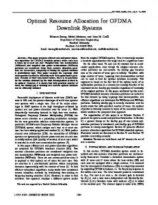
Fig. 1: Regularly placed D2D clusters in a cell, C1 = 2, C2 = 2, M = 40.
with the CVX convex optimization package [22]. Default parameters used in the simulations are given in Table III. We run two sets of experiments to evaluate the performance of the proposed algorithms, namely, regularly placed D2D clusters and randomly placed D2D clusters.
TABLE III: Default Simulation Parameters Parameter
Value
Cell radius (R)
1 km
Number of D2D receivers in each group
3
Pnoise
-114 dBm
Pathloss exponent (α)
3
D2D Pmax
20 dBm
Cell Pmax Cell γth =γth
20 dBm D2D =γth
D2D cluster size(r)
10 dB 50 m
a) Regularly placed D2D clusters: In Fig. 1, D2D groups are manually placed in six different locations and D2D transmitters and receivers are placed in the fixed locations within each group
20
with radius r. This scenario allows us to have a better understanding of the channel selection for D2D users and how it is impacted by geographical spacing. In the figure, D2D transmitters are labeled with their coordinates. The GBD algorithm finds the CU partner (or equivalent, the CU channel) for each D2D group among 40 CUs when C1 = 2 and C2 = 2. The straight lines in Fig. 1 connect D2D groups with their respective CU partners. As shown in the figure, the chosen CU partners, tend to be close to the base station to ensure the rate of the CUs. Meanwhile, the CU partners are away from the respective D2D users to reduce mutual interference between the CUs and the D2D users. Note that even for CUs at the cell edges, their SINR constraints are satisfied as guaranteed by P1. Cell Fig. 2 compares the maximum cellular throughput (without D2D users), Rmax , the throughput of
cellular users (with D2D users), RCell , and D2D throughput, RD2D , defined as follows, Cell Rmax
=
M X
log2
m=1
R
Cell
=
�
Cell Cell Pmax Gm Pnoise
M X
�
,
(60)
Cell Rm ,
(61)
RkD2D ,
(62)
m=1
RD2D =
X k∈A
where A is the set of D2D groups that are allowed to reuse at least cellular channel. As can be observed in Fig. 2, the overall network throughput, Rsum = RCell + RD2D , is greater than the Cell maximum throughput before including D2D users, Rmax . With the introduction of D2D users, the
overall throughput increases by 25% to 125%. This comes at the cost of reduced cellular throughput Cell as Rmax > RCell since adding D2D users causes interference to cellular users and decreases their
throughput. However, the reduction is relatively small, compared to the D2D throughput. Moreover, although a larger D2D cluster size leads to lower D2D channel gain and lower D2D throughput, it does not affect the cellular throughput very much. Fig. 3 shows D2D and sum rates versus C1 for different values of C2 . Both rates increase with C1 since the number of available channels for each D2D group increases and hence D2D rate increases. However, when C2 = 1, both the D2D and sum rates flatten out after a certain value of C1 . In this case, each CU can serve at most one D2D group, and increasing C1 does not increase
21
900
RD2D Rcell max
800
RCell
Throughput (bps/Hz)
700
600
500
400
300
200
100
0
20
40
60
80
100
D2D cluster size, r(m)
Fig. 2: Throughput comparison for different cluster sizes, C1 = 2, C2 = 2, M = 40.
2000
Sum rate, C =4 2
D2D rate, C2 =4
1800
Sum rate, C2 =1 1600
D2D rate, C =1 2
Rate (bps/Hz)
1400
1200
1000
800
600
400
200
2
4
6
8
C
10
12
14
1
Fig. 3: Throughput comparison for different values of C1 and C2 , M = 20.
22
the rate since there are not enough channels to allow all the D2D groups to reuse C1 channels. Also, from this figure we see that cellular throughput, which is the difference between the sum rate and the D2D rate, decreases as C1 increases. This is because of the fact that the interference from D2D groups on CUs increases with C1 . On the other hand, increasing C2 increases the D2D and sum rate for higher values of C1 since each CU can serve more D2D groups and hence there are more available channels for D2D groups. However, for lower values of C1 , since there are enough CUs in the cell to be reused by D2D groups, increasing C2 does not change the D2D and sum rates significantly. b) Randomly placed D2D users: In the second set of experiments, we follow the clustered distribution model in [23], where clusters of radius r are randomly located in a cell and the D2D users in each group are randomly distributed in the corresponding cluster. Four metrics are used to evaluate the performance: the sum throughput, Rsum , the D2D throughput, RD2D , the success rate, and the fairness index. The success rate is defined as the ratio of the number of D2D groups that found their CU partners (|A|) and the total number of D2D groups. Fairness index is defined as follows, f (R1D2D , R2D2D , . . . , RkD2D )
P ( k∈A RkD2D )2 P = |A| k∈A (RkD2D )2
(63)
The fairness index is a positive number with the maximum value of 1 suggesting an equal D2D throughput among all feasible D2D groups. The results in this section have been generated for two sets of C1 and C2 values: in part (a) of all the figures, C1 = 4 and C2 = 3; and in part (b), C1 = 1 and C2 = 1. In the case of C1 = 1 and C2 = 1, both GBD and the matching-based algorithm return the same results since both are optimal. In our previous work, [16], we have adapted the heuristic scheme in [13] for multicast D2D and compared it against proposed scheme when C1 = 1 and C2 = 1. Numerical results in [16] show that our proposed heuristic outperforms the resource allocation algorithm in [13], and thus evaluation of the heuristic in [13] is omitted here. Figs. 4 – 7 compare the performance of GBD, the greedy and the heuristic algorithms for different D2D cluster sizes (r) and different cell radii (R). From these figures, we observe that both the sum and the D2D throughput as well as the success rate decrease with the D2D cluster size. Since the channel gain of D2D link decreases when the cluster radius increases, more transmission power
23
260
Matching, R=2000m Greedy, R=2000m Proposed heursitic, R=2000m Matching, R=1000m Greedy, R=1000m Proposed heursitic, R=1000m
750
GBD, R=2000m Greedy, R=2000m Proposed heursitic, R=2000m GBD, R=1000m Greedy, R=1000m Proposed heursitic, R=1000m
700
240
230
600
Sum rate (bps/Hz)
Sum rate (bps/Hz)
650
250
550
500
450
220
210
200
190
400
180
350
170
300 20
25
30
35
40
45
50
55
60
65
160 20
70
25
30
35
40
45
50
55
60
65
70
D2D cluster size, r(m)
D2D cluster size, r(m)
(a) C1 = 4, C2 = 3
(b) C1 = 1, C2 = 1
Fig. 4: Average sum throughput versus D2D cluster radius for different cell radii (R), M = 10, K = 4
220
700
Matching, R=2000m
GBD, R=2000m Greedy, R=2000m Proposed heursitic, R=2000m GBD, R=2000m Greedy, R=1000m Proposed heursitic, R=1000m
650
600
Greedy, R=2000m Proposed heursitic, R=2000m
200
Matching, R=1000m Greedy, R=1000m 180
Proposed heursitic, R=1000m
D2D rate (bps/Hz)
D2D rate (bps/Hz)
550
500
450
160
140
400 120
350 100
300
250 20
25
30
35
40
45
50
D2D cluster size, r(m)
(a) C1 = 4, C2 = 3
55
60
65
70
80 20
25
30
35
40
45
50
55
60
65
70
D2D cluster size, r(m)
(b) C1 = 1, C2 = 1
Fig. 5: Average D2D throughput versus D2D cluster radius for different cell radii (R), M = 10, K = 4
24
1
0.98
0.97
0.98
0.96
0.94
0.96
Success rate
Success rate
1
GBD, R=2000m Greedy, R=2000m Proposed heursitic, R=2000m GBD, R=1000m Greedy, R=1000m Proposed heursitic, R=1000m
0.99
0.95
0.94
0.92
0.9
0.88
0.93
0.86
0.92
0.84
0.91
0.82
0.9 20
25
30
35
40
45
50
55
60
65
0.8 20
70
D2D cluster size, r(m)
Matching, R=2000m Greedy, R=2000m Proposed heursitic, R=2000m Matching, R=1000m Greedy, R=1000m Proposed heursitic, R=1000m 25
30
35
40
45
50
55
60
65
70
D2D cluster size, r(m)
(a) C1 = 4, C2 = 3
(b) C1 = 1, C2 = 1
Fig. 6: Average D2D success rate versus D2D cluster radius for different cell radii (R), M = 10, K = 4
1 0.95
0.95 0.9
0.9 0.85
Fairness index
Fairness index
0.85 0.8
0.75
0.7
0.8
0.75
0.7
GBD, R=2000m 0.65
0.65
Greedy, R=2000m Proposed heursitic, R=2000m
0.6
0.55
0.6
GBD, R=1000m Greedy, R=1000m
0.55
Proposed heursitic, R=1000m 0.5 20
25
30
35
40
45
50
D2D cluster size, r(m)
(a) C1 = 4, C2 = 3
55
60
65
70
0.5 20
Matching, R=2000m Greedy, R=2000m Proposed heursitic, R=2000m Matching, R=1000m Greedy, R=1000m Proposed heursitic, R=1000m 25
30
35
40
45
50
55
60
65
70
D2D cluster size, r(m)
(b) C1 = 1, C2 = 1
Fig. 7: Average fairness index versus D2D cluster radius for different cell radii (R), M = 10, K = 4
25
is required for the D2D groups to satisfy the SINR threshold constraint. This in turn causes more interference to the reused CU partner. Furthermore, it is seen from these figures that the sum throughput, the D2D throughput and the success rate of all three algorithms increase with the cell radius. This is because increasing the cell radius increases the distance between the CUs and D2D receivers and also the average distance of individual nodes to the BS. Hence, the interference from CUs to D2D receivers and the interference from D2D transmitters at the BS is decreased. Recall that the D2D rate is the maximum throughput achieved by the admitted D2D groups. It is worth mentioning that increasing the cell size leads to reduction in the cellular throughput due to the decreased link gain between the CUs and the base station. However, with the current simulation parameters, RD2D is the dominating part in the sum rate and therefore Rsum increases with the cell size in both parts (a) and (b). It can be also seen from Fig. 4 that the optimal solutions, GBD algorithm for part (a) and matching-based algorithm for part (b), has the highest sum rates. In comparison, the greedy algorithm achieves close-to-optimal sum rate, while the heuristic algorithm has a lower sum rate compared to the other two algorithms but it has the lowest complexity among them. Note that in Fig. 5, the D2D rate of the greedy algorithm exceeds that of the optimal solution for some D2D cluster sizes. This does not contradict the optimality of GBD since the objective of P1 is to maximize the sum rate not the D2D rate. Fig. 7 shows that the D2D fairness indices achieved by all algorithms are greater than 90%. Note that the fairness index calculates the fairness among all admitted D2D groups. Therefore, we can conclude that there is not much difference among D2D rates of all admitted D2D groups. D2D In Figs. 8 – 11 the performance of all proposed algorithms for different SINR thresholds (γth = Cell γth = γth ) with different numbers of CUs (M) is shown. It is seen that increasing the SINR
threshold leads to decreasing sum rates, D2D rates, and success rates since it limits the chances for D2D groups to find CU partners. It can be also observed that the total D2D throughput improves slightly with increasing number of CUs since there are more potential candidates for D2D groups to reuse.
26
500
260
240
Sum rate (bps/Hz)
Sum rate (bps/Hz)
450
400
350
300
250 10
GBD, M=15 Greedy, M=15 Proposed heursitic, M=15 GBD, M=10 Greedy, M=10 Proposed heursitic, M=10 11
12
13
Matching, M=15 Greedy, M=15 Proposed heursitic, M=15 Matching, M=10 Greedy, M=10 Proposed heursitic, M=10
220
200
180
160
14
15
16
17
18
19
140 10
20
γ (dB)
11
12
13
14
15
16
17
18
19
20
γ th (dB)
th
(a) C1 = 4, C2 = 3
(b) C1 = 1, C2 = 1
Fig. 8: Average sum throughput versus γth for different number of cellular users (M), R = 1000m, K = 4
450
140
GBD, M=15 Greedy, M=15 Proposed heursitic, M=15 GBD, M=10 Greedy, M=10 Proposed heursitic, M=10
400
120
350
110
D2D rate (bps/Hz)
D2D rate (bps/Hz)
Matching, M=15 Greedy, M=15 Proposed heursitic, M=15 Matching, M=10 Greedy, M=10 Proposed heursitic, M=10
130
300
250
100
90
80
70 200
60
150 10
11
12
13
14
15
16
γ th (dB)
(a) C1 = 4, C2 = 3
17
18
19
20
50 10
11
12
13
14
15
16
17
18
19
20
γ (dB) th
(b) C1 = 1, C2 = 1
Fig. 9: Average D2D throughput versus γth for different number of cellular users (M), R = 1000m, K = 4
27
1 1
0.95
0.95
0.9
0.9
Success rate
Success rate
0.85
0.85
0.8
0.75
0.7
0.65 10
0.8
0.75
GBD, M=15 Greedy, M=15 Proposed heursitic, M=15 GBD, M=10 Greedy, M=10 Proposed heursitic, M=10 11
12
13
0.7
0.65
14
15
16
17
18
19
0.6 10
20
Matching, M=15 Greedy, M=15 Proposed heursitic, M=15 Matching, M=10 Greedy, M=10 Proposed heursitic, M=10 11
12
13
14
γ (dB) th
(a) C1 = 4, C2 = 3
15
γ th (dB)
16
17
18
19
20
(b) C1 = 1, C2 = 1
Fig. 10: Average D2D success rate versus γth for different number of cellular users (M), R = 1000m, K = 4
1
1
0.95
0.95
0.9
0.9 0.85
Fairness index
Fairness index
0.85 0.8
0.75
0.7
0.65
0.6
0.55
0.5 10
GBD, M=15 Greedy, M=15 Proposed heursitic, M=15 GBD, M=10 Greedy, M=10 Proposed heursitic, M=10 11
12
13
14
0.8
0.75
0.7
0.65
0.6
0.55
15
16
γ th (dB)
(a) C1 = 4, C2 = 3
17
18
19
20
0.5 10
Matching, M=15 Greedy, M=15 Proposed heursitic, M=15 Matching, M=10 Greedy, M=10 Proposed heursitic, M=10 11
12
13
14
15
16
17
18
19
20
γ th (dB)
(b) C1 = 1, C2 = 1
Fig. 11: Average fairness index versus γth for different number of cellular users (M), R = 1000m, K = 4
28
VII. C ONCLUSIONS In this paper, we considered joint power and channel allocation for multicast D2D communications sharing uplink resource in a fully loaded cellular network. To maximize the overall throughput while guaranteeing the QoS requirements of both CUs and D2D groups, we formulated the optimization problem and found the optimal solution using GBD. Then, we solved a special case when each D2D group can reuse the channels of at most one CU and each CU can share their channels with at most one D2D group, using maximum weight bipartite matching algorithm. Finally, a greedy algorithm and a low-complexity heuristic algorithm were also proposed. We performed extensive simulations with different parameters such as SINR threshold, cell size, D2D cluster size, and number of CUs. Results showed that the greedy algorithm has close-to-optimal performance. In comparison, our proposed heuristic algorithm has good performance (but worse than that of the greedy) with lower computation complexity. R EFERENCES [1] T. . V0.4.1, “3rd generation partnership project; technical specification group sa; study on architecture enhancements to support proximity services (prose) (release 12),” June 2013. [2] X. Lin, J. Andrews, A. Ghosh, and R. Ratasuk, “An overview of 3gpp device-to-device proximity services,” IEEE Communications Magazine, vol. 52, no. 4, pp. 40–48, April 2014. [3] L. Lei, Z. Zhong, C. Lin, and X. Shen, “Operator controlled device-to-device communications in lte-advanced networks,” IEEE Wireless Communications, vol. 19, no. 3, pp. 96–104, June 2012. [4] K. Doppler, M. Rinne, C. Wijting, C. Ribeiro, and K. Hugl, “Device-to-device communication as an underlay to lte-advanced networks,” IEEE Communications Magazine, vol. 47, no. 12, pp. 42–49, Dec 2009. [5] A. Asadi, Q. Wang, and V. Mancuso, “A survey on device-to-device communication in cellular networks,” IEEE Communications Surveys Tutorials, vol. 16, no. 4, pp. 1801–1819, Fourthquarter 2014. [6] T. Peng, Q. Lu, H. Wang, S. Xu, and W. Wang, “Interference avoidance mechanisms in the hybrid cellular and device-to-device systems,” in IEEE 20th International Symposium on Personal, Indoor and Mobile Radio Communications, 2009, Sept 2009, pp. 617–621. [7] P. Janis, V. Koivunen, C. Ribeiro, J. Korhonen, K. Doppler, and K. Hugl, “Interference-aware resource allocation for deviceto-device radio underlaying cellular networks,” in IEEE 69th Vehicular Technology Conference, (VTC) Spring, April 2009, pp. 1–5. [8] Y. Pei and Y.-C. Liang, “Resource allocation for device-to-device communications overlaying two-way cellular networks,” IEEE Transactions on Wireless Communications, vol. 12, no. 7, pp. 3611–3621, July 2013. [9] A. Asadi and V. Mancuso, “Wifi direct and lte d2d in action,” in IFIP Wireless Days (WD), Nov 2013, pp. 1–8. [10] G. Fodor, E. Dahlman, G. Mildh, S. Parkvall, N. Reider, G. Mikl´os, and Z. Tur´anyi, “Design aspects of network assisted device-to-device communications,” IEEE Communications Magazine, vol. 50, no. 3, pp. 170–177, March 2012.
29
[11] H. Min, W. Seo, J. Lee, S. Park, and D. Hong, “Reliability improvement using receive mode selection in the device-to-device uplink period underlaying cellular networks,” IEEE Transactions on Wireless Communications,, vol. 10, no. 2, pp. 413–418, February 2011. [12] C.-H. Yu, K. Doppler, C. Ribeiro, and O. Tirkkonen, “Resource sharing optimization for device-to-device communication underlaying cellular networks,” IEEE Transactions on Wireless Communications, vol. 10, no. 8, pp. 2752–2763, August 2011. [13] M. Zulhasnine, C. Huang, and A. Srinivasan, “Efficient resource allocation for device-to-device communication underlaying lte network,” in IEEE 6th International Conference on Wireless and Mobile Computing, Networking and Communications (WiMob), 2010, Oct 2010, pp. 368–375. [14] D. Feng, L. Lu, Y. Yuan-Wu, G. Li, G. Feng, and S. Li, “Device-to-device communications underlaying cellular networks,” IEEE Transactions on Communications, vol. 61, no. 8, pp. 3541–3551, August 2013. [15] R. Afolabi, A. Dadlani, and K. Kim, “Multicast scheduling and resource allocation algorithms for ofdma-based systems: A survey,” IEEE Communications Surveys Tutorials, vol. 15, no. 1, pp. 240–254, Jan 2013. [16] H. Meshgi, D. Zhao, and R. Zheng, “Joint channel and power allocation in underlay multicast device-to-device communications,” accepted in IEEE International Conference on Communications (ICC) 2015. [17] K. Doppler, M. P. Rinne, P. Janis, C. Ribeiro, and K. Hugl, “Device-to-device communications; functional prospects for lte-advanced networks,” in IEEE International Conference on Communications Workshops, 2009, pp. 1–6. [18] A. M. Geoffrion, “Generalized benders decomposition,” Journal of optimization theory and applications, vol. 10, no. 4, pp. 237–260, 1972. [19] C. Hua and R. Zheng, “Robust topology engineering in multiradio multichannel wireless networks,” IEEE Transactions on Mobile Computing, vol. 11, no. 3, pp. 492–503, 2012. [20] M. Chiang, “Geometric programming for communication systems,” Communications and Information Theory, vol. 2, no. 1/2, pp. 1–154, 2005. [21] H. W. Kuhn, “The hungarian method for the assignment problem,” Naval research logistics quarterly, vol. 2, no. 1-2, pp. 83–97, 1955. [22] M. Grant, S. Boyd, and Y. Ye, “cvx users’ guide,” Technical Report Build 711, Citeseer. Available at: http://citeseerx. ist. psu. edu/viewdoc/download, Tech. Rep., 2009. [23] B. Kaufman and B. Aazhang, “Cellular networks with an overlaid device to device network,” in 42nd Asilomar Conference on Signals, Systems and Computers, 2008.
IEEE, 2008, pp. 1537–1541.