Aug 21, 2000 - Damperless Aeromechanically Stable Helicopters ...... [17] Takahashi, M. D., and Friedmann, P. P., "Active Control of Helicopter Air Resonance in Hover ... 500 600. 700 800. RPM. 900 1000. Fig 3: Variation of regressing lag ...
Form Approved OMB NO. 0704-0188
REPORT DOCUMENTATION PAGE
Public Reporting burden for this collection of information is estimated to avenge 1 hour per response, including the time for reviewing instructions, searching existing data sources, gathering and maintaining the data needed, and completing and reviewing the collection of information. Send comment regarding this burden estimates or any other aspect of this collection of information, including suggestions for reducing this burden, to Washington Headquarters Services, Directorate for information Operations and Reports, 1215 Jefferson Davis Highway, Suite 1204. Arlington. VA 22202-4302. and to the Office of Management and Budget Paperwork Reduction Project (0704-0188.) Washington. DC 20503. 1. AGENCY USE ONLY ( Leave Blank) 2. REPORT DATE 3. REPORT TYPE AND DATES COVERED
August 21,2000
Final Progress Report,
4. TITLE AND SUBTITLE
5. FUNDING NUMBERS
Use of Aeroelastic Couplings and Multi-Point Optimization to Design Damperless Aeromechanically Stable Helicopters
to ftaG-tfe-W-1-03+1
6. AUTHOR(S)
Dr. Farhan Gandhi 7. PERFORMING ORGANIZATION NAME(S) AND ADDRESSEES)
Dr. Farhan Gandhi Department of Aerospace Engineering, The Pennsylvania Sate University 233 Hammond Building, University Park, PA 16802 9. SPONSORING / MONITORING AGENCY NAME(S) AND ADDRESS(ES)
U. S. Army Research Office P.O. Box 12211 Research Triangle Park, NC 27709-2211
8. PERFORMING ORGANIZATION REPORT NUMBER
10. SPONSORING/MONITORING AGENCY REPORT NUMBER
Ado 3sn?.z*et-y/P
It. SUPPLEMENTARY NOTES
The views, opinions and/or findings contained in this report are those of the authors) and should not be construed as an official Department of the Army position, policy or decision, unless so designated by other documentation. 12 a. DISTRIBUTION / AVAILABILITY STATEMENT
12 b. DISTRIBUTION CODE
Approved for public release; distribution unlimited. 13. ABSTRACT (Maximum 200 words)
The present study examines the effectiveness of optimized aeroelastic couplings and rotor stiffness properties for improving the aeromechanical stability characteristics of a helicopter with a soft-inplane rotor, over a wide range of conditions, to enable the elimination of auxiliary lag dampers. A refined optimization procedure is developed that is robust and numerically efficient. Using this procedure, results indicate that it is possible to significantly reduce the peak instability levels, while enforcing constraints on design variables, and the rotating flap and lag frequencies. Concurrent optimization of the aeroelastic couplings and rotor stiffness parameters, rather than a sequential optimization strategy, yielded a design which provided maximum improvement in aeromechanical stability characteristics. The optimized design for the ground contact condition also resulted in improved lag damping in hover and forward flight. By appropriately selecting additional design parameters such as landing gear stiffness and damping it is possible to altogether alleviate instabilities in the optimized design.
20001124 033 14. SUBJECT TERMS
15. NUMBbKUr KAUriS
aeromechanical stability, aeroelastic couplings, optimization ground resonance and air resonance damperless helicopter rotors 17. SECURITY CLASSIFICATION OR REPORT UNCLASSIFIED NSN 7540-01-280-5500
18. SECURITY CLASSIFICATION ON THIS PAGE UNCLASSIFIED
16. PRICE CODE
19. SECURITY CLASSIFICATION OF ABSTRACT UNCLASSIFIED
mm QUALITY im-'Z'-"-) *
20. LIMITATION OF ABSTRACT
UL Standard Form 298 (Rev.2-89) Prescribed by ANSI Std. 239-18 298-102
USE OF AEROELASTIC COUPLINGS AND MULTI-POINT OPTIMIZATION TO DESIGN DAMPERLESS AEROMECHANICALLY STABLE HELICOPTERS
FINAL PROGRESS REPORT
FARHAN GANDHI ERIC HATHAWAY
AUGUST 21, 2000
U.S. ARMY RESEARCH OFFICE 35828-EG
PENNSYLVANIA STATE UNIVERSITY APPROVED FOR PUBLIC RELEASE; DISTRIBUTION UNLIMITED
THE VIEWS, OPINIONS, AND/OR FINDINGS CONTAINED IN THIS REPORT ARE THOSE OF THE AUTHOR(S) AND SHOULD NOT BE CONSTRUED AS AN OFFICIAL DEPARTMENT OF THE ARMY POSITION, POLICY, OR DECISION, UNLESS SO DESIGNATED BY OTHER DOCUMENTATION.
Foreword The present study examines the effectiveness of optimized aeroelastic couplings and rotor stiffness properties for improving the aeromechanical stability characteristics of a helicopter with a soft-inplane rotor, over a wide range of conditions, to enable the elimination of auxiliary lag dampers. A refined optimization procedure is developed that is robust and numerically efficient. Using this procedure, results indicate that it is possible to significantly reduce the peak instability levels, while enforcing constraints on design variables, and the rotating flap and lag frequencies. Concurrent optimization of the aeroelastic couplings and rotor stiffness parameters, rather than a sequential optimization strategy, yielded a design which provided maximum improvement in aeromechanical stability characteristics. The optimized design for the ground contact condition also resulted in improved lag damping in hover and forward flight. By appropriately selecting additional design parameters such as landing gear stiffness and damping it is possible to altogether alleviate instabilities in the optimized design.
Table of Contents FOREWORD
_
I
TABLE OF CONTENTS
II
LIST OF FIGURES
III
INTRODUCTION ROTOR-FUSELAGE ANALYTICAL MODEL. 5 5 6
VALIDATION OF ANALYTICAL MODEL EXTENSION OF ANALYSIS TO FORWARD FLIGHT STEADY INFLOW VS. DYNAMIC INFLOW
INFLUENCE OF INDIVIDUAL DESIGN VARIABLES. 6 7 7 7 8
INFLUENCE OF PITCH-FLAP COUPLING ON AEROMECHANICAL STABILITY INFLUENCE OF PrrcH-LAG COUPLING ON AEROMECHANICAL STABILTTY INFLUENCE OF STRUCTURAL FLAP-LAG COUPLING ON AEROMECHANICAL STABILTTY INFLUENCE OFBLADE FLAP STIFFNESS ON AEROMECHANICAL STAB ILTTY INFLUENCE OF BLADE LAG STIFFNESS ON AEROMECHANICAL STABILITY
PARAMETRIC OPTIMIZATION. 9 10 11 13 14
SINGLE-POINT OPTIMIZATION SINGLE-POINT OPTIMIZATION WITH MULTI-POINT CONSTRAINTS MOVING-POINT OPTIMIZATION MULTI-POINT OPTIMIZATION AT 0° AND 9° TWO-STAGE OPTIMIZATION
OPTIMIZATION RESULTS
16
AEROELASTIC COUPLINGS ONLY: No FREQUENCY CONSTRAINTS AEROELASTIC COUPLINGS PLUS FLAP, LAG STIFFNESS: NO FREQUENCY CONSTRAINTS AEROELASTIC COUPLINGS ONLY: FREQUENCY CONSTRAINTS APPLIED AEROELASTIC COUPLINGS PLUS FLAP, LAG STIFFNESS: FREQUENCY CONSTRAINTS APPLIED
17 17 18 18
SEQUENTIAL VS. CONCURRENT OPTIMIZATION
19
SEQUENTIAL OPTIMIZATION: No FREQUENCY CONSTRAINTS SEQUENTIAL OPTIMIZATION: FREQUENCY CONSTRAINTS APPLIED
19 21
INFLUENCE OF RELAXED FREQUENCY CONSTRAINTS
22
SUITABILITY OF GRADDENT - BASED OPTIMIZATION
22
VARIATIONS IN BODY FREQUENCY
24
EFFECT OF OPTIMIZED RESULTS ON AER RESONANCE STABILITY
25
SUMMARY AND CONCLUDING REMARKS
26
PUBLICATIONS PARTICIPATING PERSONNEL
.
28 28
Ill
BIBLIOGRAPHY
29
TABLES AND FIGURES
31
List of Figures 1: ROTOR - FUSELAGE PROPERTIES 31 l: MODAL DAMPING vs. ROTATIONAL SPEED AT 0° COLLECTIVE 32 FIG 2: VARIATION OF REGRESSING LAG DAMPING VS. ROTATIONAL SPEED AT 9° COLLECTIVE 32 FIG 3: VARIATION OF REGRESSING LAG DAMPING VS. ROTATIONAL SPEED AT 9° COLLECTIVE (KPC = -0.4) 33 FIG 4: VARIATION OF REGRESSING LAG DAMPING VS. COLLECTIVE AT 760 AND 820 RPM 33 FIG 5: DYNAMIC VS. STEADY INFLOW (COLL. PITCH = 5°) 34 FIG 6: DYNAMIC VS. STEADY INFLOW: MINIMUM LAG MODE STABILTTY VS. COLLECTIVE prrcH 34 FIG 7: INFLUENCE OFPTTCH-FLAP COUPLING ON LAG DAMPING (5° COLLECTIVE PITCH) 35 FIG 8: INFLUENCE OF PITCH-FLAP COUPLING ON LAG DAMPING - VARIATION OF MINIMUM DAMPING VS COLLECTIVE PITCH 35 FIG 9: INFLUENCE OF PITCH-LAG COUPLING ON LAG DAMPING (5° COLLECTIVE prrcH) 36 FIG 10: INFLUENCE OF prrcH-LAG COUPLING ON LAG DAMPING - VARIATION OF MINIMUM DAMPING VS COLLECTIVE prrcH 36 FIG 11: INFLUENCE OF FLAP-LAG COUPLING ON LAG DAMPING (5° COLLECTIVE prrcH) 37 FIG 12: INFLUENCE OF FLAP STIFFNESS ON LAG MODE STABILITY (COLL. PrrcH = 5°) 37 FIG 13: INFLUENCE OF FLAP STIFFNESS ON LAG MODE STABILTTY - VARIATION OF MINIMUM DAMPING VS. COLLECTIVE prrcH 38 FIG 14: INFLUENCE OF FLAP STIFFNESS ON LAG MODE STABILTTY -AIR RESONANCE STABILITY 38 FIG 15: INFLUENCE OFLAG STIFFNESS ON LAG MODE STABILITY (COLL. PITCH = 5°) 39 FIG 16: INFLUENCE OF LAG STIFFNESS ON LAG MODE STABILTTY - VARIATION OF MINIMUM DAMPING VS. COLLECTIVE prrcH 39 FIG 17: INFLUENCE OF LAG STIFFNESS ON LAG MODE STABILITY - AIR RESONANCE STABILITY (NOMINAL Cj/a=0.07) 40 FIG 18: INFLUENCE OF COUPLINGS OBTAINED USING SINGLE-POINT OPTIMIZATION ON LAG DAMPING (5° COLLECTIVE prrcH) 40 FIG 19: INFLUENCE OF COUPLINGS OBTAINED USING MOVING-POINT OPTIMIZATION AT 5° ON LAG DAMPING (5° TABLE
FIG
COLLECTIVE PTTCH) FIG 20: INFLUENCE OF COUPLINGS OBTAINED USING MOVING-POINT OPTIMIZATION AT 5° ON LAG DAMPING COLLECTIVE PTTCH)
41
(0°
FIG 21: VARIATION OF MINIMUM DAMPING VS COLLECTIVE PITCH USING DIFFERENT OPTIMIZATION SCHEMES FIG 22: ILLUSTRATION OF DISCRETIZATION ERROR IN OPTIMIZATION PROCESS
41
42 42 43
FIG 23: OUTLINE OF "TWO-STAGE" OPTIMIZATION PROCESS FIG 24: VARIATION OF MINIMUM DAMPING VERSUS COLLECTIVE PITCH, COMPARISON OF OPTIMIZED RESULTS WITHOUT FREQUENCY CONSTRAINTS wrra BASELINE RESULTS FIG 25: VARIATION OF MINIMUM DAMPING VERSUS COLLECTIVE PTTCH, COMPARISON OF OPTIMIZED RESULTS WITH
43
FREQUENCY CONSTRAINTS WTTH BASELINE RESULTS FIG 26: VARIATION OF MINIMUM DAMPING VERSUS COLLECTIVE PITCH, SEQUENTIAL VERSUS CONCURRENT
44
OPTIMIZATION TECHNIQUES - NO FREQUENCY CONSTRAINTS FIG 27: VARIATION OF MINIMUM DAMPING VERSUS COLLECTIVE PITCH, SEQUENTIAL VERSUS CONCURRENT
44
OPTIMIZATION TECHNIQUES - FREQUENCY CONSTRAINTS ACTIVE
45
FIG 28: VARIATION OF MINIMUM DAMPING AS FLAP FREQUENCY CONSTRAINT IS RELAXED 45 FIG 29: VARIATION OF MINIMUM DAMPING WITH CHANGES IN DESIGN VARIABLES AT THE POINT OF MINIMUM DAMPING - BASELINE CONFIGURATION 46 FIG
30: VARIATION OF MINIMUM DAMPING WITH CHANGES IN DESIGN VARIABLES AT THE POINT OF MINIMUM DAMPING - OPTIMIZED CONFIGURATION (EQ. 15) 46
IV
FIG
31:
32: 33: 34: FIG 35: FIG 36: FIG 37: FIG 38: FIG
FIG FIG
CONTOUR PLOT - VARIATION OF DECAY RATE WITH PITCH-FLAP AND PITCH-LAG COUPLING (COLL. PITCH
= 5°) 47 VARIATION OF MINIMUM DAMPING VERSUS ROLL INERTIA (COLL. PITCH = 5°) 47 INFLUENCE OF ROLL STIFFNESS ON LAG MODE STABILITY - BASELINE CONFIGURATION (COLL. PITCH = 5°)... 48 INFLUENCE OF REDUCED ROLL STIFFNESS ON OPTIMIZED RESULTS 48 INFLUENCE OF OPTIMIZED CONFIGURATION ON AIR RESONANCE STABILITY IN HOVER 49 INFLUENCE OF OPTIMIZED CONFIGURATION ON AIR RESONANCE STABILITY IN FORWARD FLIGHT (H=0.3) 49 VARIATION OF MINIMUM DAMPING VERSUS ADVANCE RATIO, BASELINE AND OPTIMIZED CONFIGURATION 50 VARIATION OF MINIMUM DAMPING VERSUS ROLL INERTIA - AIR RESONANCE STABILITY 50
USE OF AEROELASTIC COUPLINGS AND MULTI-POINT OPTIMIZATION TO DESIGN DAMPERLESS AEROMECHANICALLY STABLE HELICOPTERS Introduction Helicopters with soft-inplane rotors are susceptible to aeromechahical instabilities due to the interaction of the poorly damped regressing lag mode and the body modes [1]. Traditionally, such helicopters have been equipped with auxiliary lead-lag dampers to alleviate aeromechanical instability.
However,
associated with the use of lag dampers are issues such as hub complexity, weight, aerodynamic drag, and maintenance requirements. Modern day elastomeric dampers are also expensive, susceptible to fatigue, and exhibit complex nonlinear behaviors. Further, elastomeric dampers are sensitive to temperature, exhibiting significant loss of damping at very high or very low temperatures, and have been known to cause limit cycle oscillations in rotor blades. As a result of these factors, a variety of alternatives to auxiliary lag dampers are under consideration. The elimination of lag dampers would further simplify the hub, and reduce weight, aerodynamic drag, and maintenance costs. However, the design of a damperless, yet aeromechanically stable, configuration is truly a challenge [2,3]. While several concepts have shown promise, there has been no generally accepted solution for eliminating lag dampers. One alternative to auxiliary lag dampers for the provision of adequate aeromechanical stability margins is the use of aeroelastic couplings. Numerous studies [4—15] have demonstrated the potential of aeroelastic couplings for increasing lag mode damping. The most noteworthy investigations of the effects of aeroelastic couplings on helicopter aeromechanical stability were conducted at the Army Aeroflightdynamics Directorate at Ames. Initial investigations, begun over twenty years ago, examined the effects of pitch-lag and flap-lag couplings on an isolated hingeless rotor [4-6]. These studies indicated that a combination of these couplings was effective in increasing rotor lag damping. Further studies expanded the investigation to examine the effects of aeroelastic couplings on the coupled rotorbody aeromechanical stability of a hingeless rotor [7-9]. It was found that combinations of aeroelastic couplings were beneficial for the aeromechanical stability characteristics, particularly at higher values of collective pitch. Other work in this area [10-14] has examined the effects of aeroelastic couplings on aeromechanical stability characteristics under various operating conditions. All of these investigations have primarily focused on parametric studies of stability trends, examining discrete values of the coupling parameters at a limited number of operating conditions.
For aeroelastic couplings to be used as a practical alternative to auxiliary lag dampers, they must be able to provide acceptable levels of stability over a wide range of operating conditions (i.e. variations in thrust level, variations in body inertia, ground contact as well as airborne condition). This is a challenge, because different operating conditions often have conflicting requirements for stability augmentation. For example, a value of pitch-flap coupling having a stabilizing influence at a flat pitch condition may be destabilizing at a high thrust condition. One strategy for the determination of favorable values of aeroelastic couplings, investigated in [15], used formal optimization techniques to address these conflicting stability requirements and identify a unique combination of aeroelastic coupling parameters that significantly augmented lag mode damping over a broad range of operating conditions. While aeroelastic couplings can positively influence aeromechanical stability, they also have a significant effect on the rotor frequencies, particularly flap frequency. Values of aeroelastic couplings that are generally stabilizing for ground resonance may result in rotor frequencies that are unacceptable from a handling qualities perspective. The other fundamental parameters in determining flap and lag frequencies are the blade flap and lag stiffnesses. In addition to aeroelastic couplings, these stiffness parameters are introduced as design variables in the present study. The optimization techniques of Ref. [15] are significantly improved, yielding a faster and more numerically robust procedure. The goal of the expanded optimization procedure in the present study is to retain the stabilizing influence of aeroelastic couplings, while using the added design flexibility offered by the inclusion of rotor stiffness properties (as design parameters) to enforce constraints which will prevent excessively large changes in rotor frequencies. It will be shown that this concurrent optimization approach, where the aeroelastic couplings and fundamental rotor stiffness parameters are simultaneously considered as design parameters, is superior to a sequential approach where blade stiffness and frequency targets are set prior to any attempt to incorporate aeroelastic couplings. The concurrent optimization approach provides better performance (increased stability levels), while at the same time satisfying imposed frequency constraints.
The
aeromechanical stability characteristics of concurrently optimized designs will be examined for variations in body inertia, and operating condition (including ground contact, hover, and forward flight) to demonstrate the robustness of the optimized design. Furthermore, it will be shown that by using a combination of parameters (optimized aeroelastic couplings and rotor stiffness properties, together with landing gear stiffness and damping properties), it is possible to provide adequate aeromechanical stability margins without the use of an auxiliary lag damper.
Rotor-Fuselage Analytical Model The analytical model used in the present study represents a three-bladed rotor whose blades have uniform mass distribution and are assumed to undergo rigid flap rotations (ß) and lag rotations (Q about springrestrained offset hinges. The fuselage is assumed to undergo rigid body roll and pitch rotations (a* and Oy) about its center of mass (located directly below the hub). The aerodynamic loads on the rotor blades are calculated using quasi-steady strip theory, assuming a uniform inflow. The rotor-fuselage equations of motion are linearized about the equilibrium condition to obtain the perturbation equations. The perturbation flap and lag equations for the individual blades (having periodic coefficients in the rotating coordinate system) are transformed to the non-rotating coordinate system using Multiblade Coordinate Transforms.
For ground contact or hover conditions, this
transformation yields a collective equation and two cyclic equations in the non-rotating system for flap and lag motions, all of which have constant coefficients (independent of azimuthal position of the blade). The two cyclic flap and cyclic lag equations couple with the fuselage motions, and thus need to be retained for the aeromechanical stability analysis. In addition, the collective flap and collective lag equations are retained and used to track the rotating flap and lag frequencies. Thus, the rotor-fuselage model for a three-bladed rotor has eight degrees of freedom: collective flap (ß0), cyclic flap (ßic and ßls), collective lag (Q, cyclic lag (£ic and £ij). and fuselage roll and pitch (a, and cty). In the non-rotating frame the resulting constant coefficient system can be represented in the following form:
[M]{qMc]{a>[KM={0}
(D
where [M], [C], and [K] are the 8 x 8 mass, damping and stiffness matrices, and {q}=lP.
ßie
ßb
Co
Cc
Cls
«x
aj
(2)
The eigenvalues of Eq. 1 yield the modal frequencies and decay rates. The aeroelastic coupling parameters considered (and contained in Eq.l are: pitch-flap coupling (KPß), pitch-lag coupling (K^), and structural flap-lag coupling (Rß and R^). The pitch-flap and pitch-lag couplings result in perturbations in blade pitch, A0, due to perturbation flap and lag motions. Thus,
Aek=-Kppßk-KP^k
(3)
where the subscript "k" denotes the k* blade. Careful attention should be paid to sign convention here. In the present model, ß is positive for flap-up motion, C, is positive for lag-back, and A6 is positive for nose-up pitching motion. Thus, a positive value of Kpp would result in a flap-up, pitch nose-down coupling, while a positive KP^ would yield a lag-back, pitch nose-down coupling. Structural flap-lag coupling is a result of blade flap and lag flexibility outboard of the pitch bearing. In Ref. [16] flap-lag coupling was modeled using orthogonal hub flap and lag springs kpH and k^H» respectively, inboard of the pitch bearing; and orthogonal blade flap and lag springs kßB and k^B, respectively, outboard of the pitch bearing. Based on this system of springs, effective flap and lag flexural stiffnesses kß and k; were defined as kp=_k!HkiL_
k?=J^kiB_
(4)
+
kßH+kßB
kyj kcB
Structural flap-lag coupling parameters are then defined as Rß=kß/kpB
R(.=k^/k?B
(5)
where, for example, Rß = 1, means the flap flexibility is entirely outboard of the pitch bearing with the hub being rigid in flap, and Rß = 0, means the flap flexibility is entirely in the hub with the region outboard of the pitch bearing being rigid in flap. In general, if there is some flexibility in both the hub and the blade, Rß and R^ assume values between 0 and 1. A complete formulation of the structural flaplag coupling parameters is found in Ref. [15]. Blade stiffness parameters are defined to allow variations about the nominal flap and lag stiffnesses, Kß and K?, respectively. Thus, Kß=Kß(l + AKß) (6)
K^=KC(I+AKJ where AKß and AK^ are non-dimensional design parameters representative of a percent change in stiffness about the baseline values.
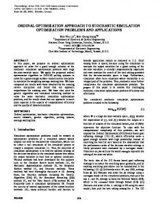
Validation of Analytical Model The analytical model is validated using the experimental results in Ref. [8]. Rotor-fuselage properties for this configuration are given in Table 1. Figure 1 shows the variation in regressing lag damping, body pitch damping, and body roll damping, for 0° collective. It is seen that the regressing lag damping, as well as body pitch and roll damping compare very well with experiment. Figures 2 and 3 show the variation of regressing lag mode damping versus rotational speed at 9° collective for the cases of no aeroelastic coupling, and for a pitch-lag coupling, KP^ = -0.4, respectively. Once again, in both cases, the analytical predictions compare well with experimental results. Finally, Figure 4 show variations of regressing lag damping versus collective pitch at rotational speeds of 760 and 820 RPM. Again, the analytical results compare very well with experiment.
Extension of Analysis to Forward Flight The aeromechanical stability analysis described above is extended to the forward flight condition. For this case, the periodic coefficients of the equations are not eliminated even after transforming to the nonrotating system. Thus, the matrices are functions of blade azimuthal position, and the system can be represented as:
[M]{q}f[c(V)]{q}f[K(V)]{q}={0}
™
The eigenvalues of the above equations can be obtained using either the Floquet Transition Matrix theory or a constant coefficient approximation. In the second approach, the matrices are numerically evaluated at a prescribed number of points around the rotor azimuth and simply averaged. The eigenvalues of the resulting constant coefficient equations then yield the rotor-body frequency and damping characteristics in forward flight. The constant coefficient approximation technique, which is much simpler than the Floquet Transition matrix approach, has been shown to be accurate (see Ref. [17]), and is used in the present study to evaluate aeromechanical stability characteristics in forward flight.
Steady Inflow vs. Dynamic Inflow As mentioned previously, the present analysis uses a uniform inflow model to determine the aerodynamic loads on the rotor blades. It has been suggested that accurate prediction of helicopter aeromechanical stability characteristics requires the inclusion of a dynamic inflow model. However, this is not necessarily the case. Figures 5-6 compare the lag mode stability characteristics of both a baseline (no couplings) configuration and a configuration with optimized aeroelastic couplings (from Ref. [15]), using both a steady inflow model and a dynamic inflow model. Figure 5 shows that at a collective pitch of 5 degrees, dynamic inflow has an insignificant effect on lag damping for both the baseline and optimized configuration. From figure 6 (a plot of the minimum damping, corresponding to the bottom of the resonance bucket, versus collective pitch) it is seen that this observation holds true over the entire range of collective pitch values under consideration. Dynamic inflow is known to have a significant effect on the damping of body modes, but has a much smaller effect on lag mode damping. Further, while dynamic inflow may affect the specific damping level for a particular configuration at a given operating condition, it does not affect the overall stability trends with variations in rotor speed, collective pitch, or aeroelastic coupling parameters. Since the present study is an investigation into the effects that aeroelastic couplings have on lag mode stability trends, rather than a rigorous calculation of aeromechanical stability levels for a specific full-scale design effort, dynamic inflow has not been included in the subsequent results.
Influence of Individual Design Variables Before conducting any optimization studies, it is useful to develop an understanding of the individual influence of each design variable on aeromechanical stability. The baseline rotor configuration used for the numerical studies in this paper is a model hingeless rotor tested at NASA-Ames [7], whose properties are given in Table 1. This baseline configuration has no aeroelastic couplings (i.e. KPß, K^, Rp, Rc = 0).
Influence of Pitch-Flap Coupling on Aeromechanical Stability In Figure 7 it is seen that for 5° collective pitch, positive pitch-flap coupling (flap up - nose down) is able to increase the minimum damping at resonance conditions. The results in Figure 7 indicate that the increase in minimum damping is a nonlinear function of degree of positive pitch-flap coupling. After obtaining a significant increase in minimum damping for small values of pitch-flap coupling, further increases in pitch-flap coupling result in smaller additional increases in minimum damping.
Figure 8 shows that this increase in the level of minimum damping is found at all values of collective pitch, though the degree of stabilization is increased at high collective. Examination of plots similar to Figure 8 for other values of pitch-flap coupling indicates that the trend of smaller increases in minimum damping as Kpß becomes larger holds true for all values of collective pitch.
Influence of Pitch-Lag Coupling on Aeromechanical Stability Figure 9 shows the influence of negative pitch-lag coupling (lag back - nose up) on lag damping in ground resonance at 5° collective pitch. It is seen that while there is no change in the minimum damping values at resonance, negative pitch-lag coupling increases the damping away from resonance. The net effect is that the range of rotational speeds over which instability is encountered can be significantly reduced. Figure 10 shows that effect of negative pitch-lag coupling varies greatly with collective pitch. Above 5° collective, negative KP^ is seen to be quite stabilizing, whereas below 5° collective, it is destabilizing. Examining plots similar to Figure 9 at lower values of collective pitch shows that this destabilizing effect is happening in the resonance region. Away from resonance, negative pitch-lag coupling is stabilizing for all values of collective pitch. In Figures 7 and 9 it is seen that both negative pitch-lag coupling as well as positive pitch-flap coupling tend to shift the resonance condition to a slightly lower rotational speed.
Influence of Structural Flap-Lag Coupling on Aeromechanical Stability Figure 11 shows that structural flap-lag couplings are unable to increase the minimum damping at roll resonance. Of the two parameters, Rß and R^, regressing lag damping is more sensitive to changes in Rß. The regressing lag damping with R^ = 1 is almost identical to the baseline. For the case Rß = R^ = 1 (results not shown in Figure 11), the regressing lag damping was found to be almost identical to the case Rß = 1, R; = 0. It should be mentioned that structural flap-lag coupling would have a larger influence at higher values of collective pitch.
Influence of Blade Flap Stiffness on Aeromechanical Stability Figure 12 shows the influence of rotor blade flap stiffness on ground resonance stability. Increasing the flap stiffness is seen to have a mild stabilizing effect. In Figure 13 it is seen that this trend holds true for
8
all values of collective pitch, with the degree of stabilization increasing at high collective pitch. This is consistent with the findings in [7], where increased flap stiffness was shown to have a beneficial influence on stability boundaries for blade lead-lag frequencies greater than approximately 0.6 (as is the case with the present model). Figure 14 shows that this stabilizing trend with increased flap stiffness continues for the hover condition (however, at the nominal speed of the rotor of 720 RPM, the increase in stability is insignificant). In the present study all "hover" results are obtained by setting the fuselage pitch and roll spring stiffnesses to zero and trimming the rotor to a constant (non-zero) thrust. It can also be seen in Figures 12 and 14 that the rotational speed at which resonance occurs is unchanged. These results would seem to contradict the findings in [7], where increased flap frequency was found to destabilize air resonance. However, the air resonance results in [7] were for a flat pitch condition, whereas the present air resonance analysis trimmed collective pitch to produe a constant thrust. Thus, direct comparisons between the two studies may not be appropriate. Although increased flap stiffness has an overall positive influence on ground and air resonance stability, it should be noted that blade flap stiffness cannot be increased arbitrarily. Other concerns, such as dynamic stresses in the flap flexure, set an upper limit on the level of flap stiffness that can be realized in practice.
Influence of Blade Lag Stiffness on Aeromechanical Stability Figure 15 shows the influence of rotor blade lag stiffness on ground resonance stability. Increasing lag stiffness reduces the level of instability slightly, while also shifting the maximum instability to a higher rotational speed. This shift in the rotational speed at which resonance occurs is expected, because increasing the rotor lag stiffness will cause the regressing lag mode to coalesce with the body modes at a higher rotational speed, delaying the onset of aeromechanical instabilities. This is again consistent with the results reported in [7], where increased lag frequencies generally improved stability boundaries. In Figure 16, it can be seen that as collective pitch is increased, the degree of stabilizing influence from increased lag stiffness decreases, and at very high pitch settings, increased lag stiffness can actually be destabilizing. Figure 17 shows that for the hover condition, increasing lag stiffness again shifts the instability to a higher rotational speed, and this can potentially lower air resonance stability margins at the nominal speed (720 RPM). In addition, excessively large values of lag stiffness would produce unacceptable dynamic stress levels in the blade flexure.
Parametric Optimization Formal optimization procedures were used with the goal of determining a combination of the design variables that will alleviate aeromechanical instabilities, while constraining flap and lag frequencies within prescribed values. The design variables considered were rotor pitch-flap coupling parameter (KPß), pitch-lag coupling parameter (KPi;), structural flap-lag coupling parameters (Rß and R^), as well as changes in blade flap stiffness (AKß) and lag stiffness (AK^). Parametric design optimization is implemented using the subroutine DNCONF, from the IMSL mathematical library subroutines. This is a gradient-based optimizer which uses a successive quadratic programming algorithm to solve the general nonlinear programming problem with nonlinear constraints. The user of this subroutine is required to define a set of design variables, as well as provide a routine which evaluates some objective function. The optimizer then seeks to find the combination of design variables such that the objective function is minimized. Gradients are calculated numerically for each iteration to determine the search direction, using a finite difference method. The objective function must be selected thoughtfully, in order to achieve the desired results. In the present study, a number of objective functions are formulated before satisfactory results are achieved. These successive formulations are presented here, along with discussions of intermediate results, to provide insight into the subtleties involved in successfully formulating this design optimization problem.
Single-Point Optimization Design optimization is initially carried out at a moderate thrust condition (collective pitch of 5°). Since the baseline system (without, any aeroelastic couplings) reaches minimum damping at about 770 RPM, the objective function to be minimized is defined as follows: F(Dj)=(a770-ä770)2
(8)
where a770 denotes the regressing lag mode decay rate at 770 RPM, cf^o denotes the desired regressing lag mode decay rate at 770 RPM (which was set at -0.1, stable), and Dj denotes the jm design variable. The following constraints are imposed on the design variables:
10 -i.0 ^ 0.2
a
> 8 -0.2
a
/e
/
Y
c>
1
:
1
l
§yS
i
I
°/\
i
0\
!
J
QJ
\ \
unstable
I1
«xy
■
i
\
"eg-f
-0.8 : " i
i
i
e\
-0.6 ~
500
S^
|
1
\ _ :
. -0.4 ".
1
c■) I
V
j
t
1
i
j
; i
i
rill. .1
i
600
700
800
j i
i
i
1
!
900
1
11 ..!.._
1000
RPM
Fig 2: Variation of regressing lag damping vs. rotational speed at 9° collective
33
500
600
700
800
900
1000
RPM
Fig 3: Variation of regressing lag damping vs. rotational speed at 9° collective (Kp; = -0.4)
D
2
Experiment (820 RPM) Theory (820 RPM) Experiment (760 RPM) Theory (760 RPM)
4 6 Collective Pitch (deg)
8
Fig 4: Variation of regressing lag damping vs. collective at 760 and 820 RPM
34
500
600
700
900
800
1000
RPM
Fig 5: Dynamic vs. steady inflow (Coll. Pitch = 5°)
4
6
8
12
Collective Pitch, deg. Fig 6: Dynamic vs. steady inflow: minimum lag mode stability vs. collective pitch
35
500
600
700
900
800
1000
RPM
Fig 7: Influence of pitch-flap coupling on lag damping (5° collective pitch)
Ä
o
sc
0
:
I
-0.1 '
a c o -0.2 C0
I
unstable
i
i
!
v
I i
i i
i !
i
^
|
|
|
|
4p = 0.5
CD
DC
(8
oc
i
7,
a a
-0.3 I I I I
O DC
\IXSV
■0.4
^ X i
i
:
! /K;
S a -0.5 a E
I
i
Baseline !
3
E ■0.6 c -
1 I
1
I
1
1
1
1 -
2
,
, , 1
4
I
\u i
i
i
,
.
'■ i
6
i '-L i 1
8
'
L-
10
, , , , 12
Collective Pitch (deg)
Fig 8: Influence of pitch-flap coupling on lag damping - variation of minimum damping vs collective pitch
36
500
600
700
900
800
1000
RPM
Fig 9: Influence of pitch-lag coupling on lag damping (5° collective pitch)
^
u0)
JO
8c
a c o » a OC
0
: II " unstable -0.1 ■0.2
ö ■0.3 a Sa -0.4 DC
i !
S.
'
!
i
■
i
!
:
!
|
:
i\
!
1 /
:
i i*
1
\i^
s
i i i
!
...
Nv !
—-—i«.
Baseline i
i
i
i
i
i
i
i
t
i
4
6
1
t
1
1
1
8
1
1
t
1
10
12
Collective Pitch (deg)
Fig 10: Influence of pitch-lag coupling on lag damping - variation of minimum damping vs collective pitch
37
500
600
700
900
800
1000
RPM
Fig 11: Influence of flap-lag coupling on lag damping (5° collective pitch)
0.6
I "I
r-vn— 1
1
1
1
1
1
1
1
1
1
1
J
1
1
j
1
1
1
1
0.4 -■
1 tJ 0.2 a» e>
0
_
stable %
:
: t
1 Increasing ^s^ \ \ \ Flap Stiffness jf
«3 U U
Uli g
w
•O -0.2
■0.4
l A AK =0.4 jf/ ß :
\ J\ :' M
-
-AK =o.a (Baseline) —^P^ .
-0.6
500
ß
AK
V
-*^^
, , , ,
r
600
i
l
t
I
l
l
l
700
t
1
800
(
'.
U _0.4
:
ß: l
l
l
I
900
l
l
I
i
1000
RPM Fig 12: Influence of flap stiffness on lag mode stability (Coll. Pitch = 5°)
-0.1
1 1 1 1
0
1 1 1 1
38
is
unstable
:
Nk
-0.2
as es u -0.3 u s Q B
e s
-0.4
B ©
-0.5
:
:
i^C"-:
:
|
-0.7
:
i /i^C"i
;
Baseline:
1 II"
-0.6 -
i AK =0.4
i
i
i
i
i
i
4
i
i
i
i
6
i
i
8
i
i
i
i
10
i
i
i
12
Collective Pitch, deg. Fig 13: Influence of flap stiffness on lag mode stability - variation of minimum damping vs. collective pitch
500
600
700
800
900
1000
RPM Fig 14: Influence of flap stiffness on lag mode stability - air resonance stability (nominal CT/o = 0.07)
39
500
600
700
900
800
1000
RPM
Fig 15: Influence of lag stiffness on lag mode stability (Coll. Pitch = 5°)
-i—i—I—i—i—i—|—i—r—i—I—i—i—i—|—r-
-0.1 -V
t AK:=0.4
unstable
:
es
es
Q
s
S I -0.4
-0.6 -0.7
4
6
8
10
Collective Pitch, deg. Fig 16: Influence of lag stiffness on lag mode stability - variation of minimum damping vs. collective pitch
40
Increasing Lag Stiffness
-0.1 -0.2 _i 500
i
i
i
i_
600
700
800
900
1000
RPM
Fig 17: Influence of lag stiffness on lag mode stability - air resonance stability (nominal Cj/o = 0.07)
500
600
700
800
900
1000
RPM
Fig 18: Influence of couplings obtained using single-point optimization on lag damping (5° collective pitch)
41
.g 3 'iiiiiii.il
500
600
i
i
i
700
i
i
800
i
i
i
i
l
900
i
i
i
i
1000
RPM
Fig 19: Influence of couplings obtained using moving-point optimization at 5° on lag damping (5° collective pitch)
500
600
700
800
900
1000
RPM
Fig 20: Influence of couplings obtained using moving-point optimization at 5° on lag damping (0° collective pitch)
42
^ 0.8 u o M
/ !
^ 0-6 u
JDjjtiroized at .9°
Io 0.4
^l—s
CO
o
5E 0.2 o
n
0
2 £-0-2 So CO
Q -0.4 E 3
| -0.6
I ' -0.8
0
2
4
6
8
10
12
Collective Pitch (deg) Fig 21: Variation of minimum damping vs collective pitch using different optimization schemes -0.35
1
!
j
1
^—^
"
j
1
^
(
\
j
j
(
j
1
1
1
1
1
1
1—I'" 1
III! / ■
Baseline
.
/
i*
« u -0.4
JA
-K
/ \
=-(D.4
\
-
\ \
es u es u CU •ö -0.45
V
^s
xf
-
XD
B
v
-0.5 740
i
ill
i i
■
i
:
i
745
i
i
i
i
750
i
i
i
i
r
755
i
i
i
1
760
I
r
i
I
765
770
RPM Fig 22: Illustration of discretization error in optimization process
43
Main Optimization Inner-Loop Optimization
F(Dj = -clag|Dj
Dk=Lo,e| Iterate until Converged F D
( j)=amin|(ek,ßk)=Dk
Iterate until Converged Fig 23: Outline of "two-stage" optimization process
4
6
8
10
Collective Pitch, deg. Fig 24: Variation of minimum damping versus collective pitch, comparison of optimized results without frequency constraints with baseline results
44
0.6
-i—i—i—i—i—i—r-
Optimized, Couplings + AK , AK
0.4
es m
« *w* u >» es u u s 0) M Q B
ss
S
O
2
0.2
stable
0 -0.2
Baseline
Optimized -Couplings
o 5? PS -0.4 B
-0.6 Frequency Constraints Applied -0.8
_J
i
i
l_i
i
i
I
4
i
i
i
■
I
6
8
■
l
10
12
Collective Pitch, deg. Fig 25: Variation of minimum damping versus collective pitch, comparison of optimized results with frequency constraints with baseline results
4
6
8
10
Collective Pitch, deg. Fig 26: Variation of minimum damping versus collective pitch, sequential versus concurrent optimization techniques - no frequency constraints
45
0.3
—i—i—i—|—i—i—i—|—i—i—i—|—i—i—i—|—i—i—i—|—i—i / f
Frequency Constraints Applied
//
Sequential:
0.2
Couplings 1st, Stiffness 2nd // 9i
O
SS
«J
stable
u e
OB
°
I*
0.1 -
So s o
I« 0.2 ->--~.~V
Sequentiä'I: Stiffness 1* Couplings 2nd i
-0.3
i
4
i
i
I
i
i
i
i
6
i
i
i
8
i
i
i
i—
12
10
Collective Pitch, deg. Fig 27: Variation of minimum damping versus collective pitch, sequential versus concurrent optimization techniques - frequency constraints active
I I 1 1
1—1—1—1—1—1—1—1—1—1— I
1
1
1
[■
r-'i
■ i
s^^^'f
-0.15-
II
1
'
Constraint No Longer Active -
-0.16 -
-0.17; es u % B -
:
°E Sg -0.18-
-
J
s ,3-0.19o S
:
- / -0^ -0.21
I
•
1
1.15
i
'■•■■
1.2
1.25
t
i
i
1
i
t
i
1.3
Flap Frequency Constraint (/rev)
Fig 28: Variation of minimum damping as flap frequency constraint is relaxed
46 -0.3
i
i
i
i
i
i
1
1
1
1
_i
-0.5
1
i
1
■
r-
'
0 0.5 Design Variable Value
Fig 29: Variation of minimum damping with changes in design variables at the point of minimum damping - baseline configuration -0.1
T
1
1
1
1
1
1
r
-1
1
1
r-
-r
1
1
r-
K if no frequency constraint
; Damping Level of fl -0.15 l9P ^.^.P^8P? ... Optimized values /
2 « ^~* >>