was used to optimize the etching of submicron ... Deep reactive ion etching is widely used to create high ... An Alcatel 601E reactor has been used for the.
Optimization of two silicon cryoetching processes (STiGer) for submicron trenches and via applications H. Jiang1, R. Dussart1, L.E. Pichon1,2, C.Y. Duluard1, E.H. Oubensaid1, J. Pereira1, P. Lefaucheux1, M. Boufnichel2, P. Ranson1 1
2
GREMI, 14 rue d’Issoudun, BP 6744, 45067 Orléans Cedex 2 STMicroelectronics, 16 rue Pierre et Marie Curie, BP 7155, 37071 Tours Cedex 2
Selected Topic: Etching
Abstract — Two silicon cryoetching processes were recently designed at GREMI laboratory. A high density, low pressure ICP industrial reactor was used to optimize the etching of submicron trenches and vias. An aspect ratio as high as 20 was obtained for 0.8 µm wide trenches. Undercut was reduced to below 100 nm. I.
INTRODUCTION
Deep reactive ion etching is widely used to create high aspect ratio microstructures for integrated devices applications and Micro-Electro-Mechanical Systems (MEMS). There are two main technologies: Cryogenic process and Bosch process. In standard cryogenic process [1], the wafer is cooled down to about −100°C. A plasma of SF6 – O2 is created to both etch the bottom of the structures and protect their sidewalls simultaneously. The passivation layer SiOxFy only forms at low temperature of the substrate in our experimental conditions. Ion bombardment is necessary to remove (or to avoid the formation of) the passivation layer on upward-facing surfaces. Consequently an anisotropic etching can be realized. While standard cryoetching of silicon achieves quite high etch rates, it remains very sensitive to the substrate temperature, and difficult to control. The Bosch process consists of alternating isotropic etching steps (SF6 plasma) and passivation steps (C4F8 plasma) at ambient temperature in order to achieve nearly vertical structures. Until now, the Bosch process, which is widely used in the MEMS industry, appeared as more robust than the standard cryogenic process. But this process has the disadvantage to deposit a polymer not only on etching profiles, but also on the reactor walls. This effect is sometimes an issue in micro component elaboration. As a result, additional steps are required to remove this layer from both the etched profiles and the chamber walls. In order to overcome these drawbacks, two alternated cryogenic etching processes (STiGer processes) were developed in GREMI laboratory [2] and were patented [3]. The first one alternates a short passivation step using SiF4 – O2 plasma with a short isotropic etching step (SF6 plasma). The other one alternates the same passivation step with long anisotropic etching step (SF6 – O2) plasma. Both of them only work at cryogenic temperature (about –85°C).
These processes are much more robust than the standard cryogenic process. They also avoid the main drawback of the Bosch process since no additional treatment is needed in these processes to remove the deposited layer, because the SiOxFy film has the property to desorb when the substrate is warmed up to ambient temperature[2-5]. In this paper, we present our optimizations on these new alternated cryogenic processes applied to submicron trenches and through-wafer interconnects (vias). II.
EXPERIMENT
An Alcatel 601E reactor has been used for the experiments. It is composed of an inductively coupled plasma source and a diffusion chamber. There is a cooling system with liquid nitrogen on this machine in order to regulate the temperature between -150 °C and 40 °C. The chuck is equipped with an electrostatic clamping system to provide a good uniformity of temperature. The process gases we usually use are SF6, O2 and SiF4. A Leica Cambridge Ltd., S360. Scanning electron microscope is used to characterize the etched profiles of the experimental tests. III.
EXPERIMENTAL RESULTS
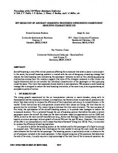
A. Submicron Etching In the submicron etching process, an efficient ionic bombardment is needed in order to avoid the formation of the passivation layer at the bottom of structure and to get a high aspect ratio structure. Based on previous experiments [2-5], we fixed the process temperature at -85°C and the SF6 flow at 230 sccm. A study on the relation between Bias and gas pressure was firstly done for SF6 plasma and SiF4 – O2 plasma (see Fig. 1) We observed that an optimal bias value is obtained at 3 Pa gas pressure for the SF6 plasma (2000W RF source, 50W bias power) and then decreases at higher pressure. This decrease is probably due to the increase of negative ion density, which is favored at high pressure. In the passivation step (SiF4/O2 plasma), the bias value increases quickly when the gas pressure changes from 1 to 3 Pa and then keeps increasing but more slightly. As a consequence, we decided to work at 3 Pa, which is a good compromise. After some tests with different passivation gas flows and pulse time, a good etch profile has been obtained for this 0.8 µm trench (see Fig. 2). The etch depth is 15.6 µm for 6 minutes process time. The aspect ratio in this process is about 20 : 1. The undercut was maintained below 100 nm.
The roughness of the sidewalls was remaining below 200 nm. 70 60 SF6: 230 sccm
Bias (V)
50 SiF4: 60 sccm O2 : 60 sccm
40 30
which corresponds to an etch rate of 9 µm/min. The undercut was stopped and remained below 600 nm. While this type of process was successfully used for trench features [2, 3], it is not yet completely optimized for via applications because some small etching defects appear between each alternation. These defects, which are probably due to a non uniform SiOxFy deposition layer at the bottom of the holes, have to be avoided. A further optimization of the passivation parameters will be carried out and should solve this trouble.
20 10 0 1
2
3
4 5 Pressure (Pa)
6
7
8
Figure 1. Study on Pressure & Bias relation for SF6 and SiF4/O2 plasmas with 2000W source power and 50W Bias power
Figure 4. 5 times alternated process for Via applications
IV.
CONCLUSIONS
In this paper, we presented the etching performances of two silicon cryoetching processes for micro-fabrication.
Figure 2. Best result obtained for 0.8 µm trench etching process
B. Via Applications The other advanced alternated etching process, including a long anisotropic etching step (SF6/O2) and a relatively short passivation step (SiF4/O2), was used in this via process. A study of anisotropic etching step was firstly done. In Fig. 3, we can see the etching result of a 2 minutes anisotropic standard etching process with SF6 – O2 plasma. A good etching profile with a high etch rate (13µm/min) was obtained.
In submicron etching application, we developed an alternated etching process which enabled an etching depth of 15.6 µm for 0.8 µm trenches. An etch rate of 2.6 µm/min was reached. In via applications for which a higher silicon etching rate is required, we tested the second cryoetching process. A high etch rate of 9 µm/min was obtained for 16 µm diameter holes. Some more experimental tests will be performed in order to well control this process and to attaint a higher depth without defects. ACKNOWLEDGMENT We want to thank ST Microelectronics Tours for their support during this process development. REFERENCES [1]
[2] [3]
[4] Figure 3. 2 minutes anisotropic etching step
Then, we alternated 1 minute anisotropic etching step with 4 second passivation step. In Fig. 4, we show the result after 5 alternations. We obtained an etch depth of 48.7 µm,
[5]
M.J. de Boer, J. G. E. Gardeniers, H. V. Jansen, E. Smulders, M-J. Gilde, G. Roelofs, J. N. Sasserath, and M. Elwenspoek , J. Microelec. Syst., 11(4), (2002) 385 T. Tillocher, R. Dussart, L.J. Overzet, X. Mellhaoui, P. Lefaucheux, M. Boufnichel, P. Ranson, J. Electrochem. Soc., 155 (2008) D187 R. Dussart, T. Tillocher, P. Lefaucheux, P. Ranson, X. Mellhaoui, M. Boufnichel, L. J. Overzet «Procédé de gravure profonde anisotrope du silicium », FR 0554095 (2007) R. Dussart, X. Mellhaoui, T. Tillocher, P. Lefaucheux, M. Boufnichel , P. Ranson, J. Microelectronic Eng., 84(2007) 1128 X. Mellhaoui, R. Dussart, T. Tillocher, P. Lefaucheux, P. Ranson, M. Boufnichel, L.J. Overzet, J. Appl. Phys., 98 (2005) 104901


![[PDF] Optimization of Chemical Processes - Google Sites](https://m.moam.info/img/260x300/pdf-optimization-of-chemical-processes-google-site_64777308097c4744708bb995.jpg)