modulation-format-independent all-optical clock recovery with a simple and straight-forward configuration. We then analyze the clock enhancement technique ...
NOC 2011
CPI - 8
Optimizing Clock Enhancement to Achieve Modulation-Format-Independent All-Optical Clock Recovery Zuqing Zhu, Member IEEE School of Information Sci. & Tech., University of Science and Technology of China, Hefei, Anhui 230027, China
Email: {zqzhu}@ieee.org � Abstract—We investigate a clock enhancement technique with signal pre-distortion using a semiconductor optical amplifier based Mach-Zehnder interferometer (SOA-MZI). Working together with a Fabry-Perot filter (FPF) based all-optical clock recovery module, this technique achieved modulation-format-independent all-optical clock recovery with a simple and straight-forward configuration. We then analyze the clock enhancement technique with numerical simulations. The simulations determine the optimal operation points of the SOA-MZI for RZ and NRZ inputs and demonstrate effective clock amplitude improvement and clock amplitude fluctuation reduction.
I. INTRODUCTION
O
reamplification, reshaping and retiming (3R) regeneration is an important enabling technology that ensures scalability and robustness in future all-optical networks. To achieve full 3R optical regeneration, we need to realize all-optical clock recovery without requiring high-speed electronics. Previous research has demonstrated a number of all-optical clock recovery techniques [1,2,3,4]. However, most of these techniques can only work with either return-to-zero (RZ) or non-return-to-zero (NRZ) format. Hence, modulation-format-dependence becomes a drawback for implementation. Recently, we have proposed a clock enhancement technique that uses signal pre-distortion in a semiconductor optical amplifier based Mach-Zehnder interferometer (SOA-MZI) [5,6]. In this paper, we investigate this technique with a simulation model using realistic SOA-MZI parameters and demonstrate that modulation-format-independent all-optical clock recovery can be achieved with a simple configuration. The numerical simulations also locate the optimal operation points of the SOA-MZI for various input encodings (e.g. RZ and NRZ). Effective clock amplitude improvement and clock amplitude fluctuation reduction can be achieved for all-optical clock recovery with the optimization. PTICAL
Fig. 1 Operation principle of all-optical clock recovery with a FPF and a SOA
signals with narrowband optical filtering. A Fabry-Perot filter (FPF) with a free spectral range (FSR) matched to the signal bit-rate, and a relatively large finesse (typically > 50) works effectively in this situation [4,7]. Fig. 1 explains the operation principle of the all-optical clock recovery module that is built with a FPF and a semiconductor optical amplifier (SOA). The optical spectrum of the return-to-zero (RZ) signal consists of continuous spectral components from data modulation and line spectral components from the clock and its harmonics. When passing through the all-optical clock recovery module, the clock spectral components get transmitted, while the data modulation components get suppressed. The FPF removes most of the data modulation and provides optical clock pulses
II. ALL-OPTICAL CLOCK RECOVERY WITH FPF All-optical clock recovery can be achieved through extracting the clock spectral components from optical
978-1-86135-373-3/11/$25.00 ©2011 IEEE
110
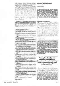
Fig. 2 Intensity of recovered 10 GHz clock component vs. LEAF fiber transmission distance
NOC 2011
CPI - 8
Fig. 3 Setup of the all-optical clock enhancement and recovery module
matching to its FSR (i.e. signal bit-rate) frequency. However, when the data modulation contents long sequences of repeated zeros, the recovered clock amplitude can decay due to pattern-dependence [7]. This is the reason why the module has to include a gain-saturated SOA to reduce the pattern-dependent amplitude variations [4]. The limiting amplification in the saturated SOA helps suppress the residual data modulation and enhances the recovered clock’s side-lobe suppression ratio.
Fig. 4 Simulated eye-diagrams for clock recovery from dispersed RZ signal
III. SIGNAL PRE-DISTORTION FOR CLOCK ENHANCEMENT We have discussed FPF-based all-optical clock recovery for undistorted RZ signals in Section II. However, during fiber transmission, physical layer impairments, such as amplifier noise, chromatic dispersion (CD), polarization-mode dispersion (PMD), and fiber nonlinearities can degrade signal quality and input a distorted signal to the all-optical clock recovery module. Fiber dispersions such as CD and PMD add complexity to clock recovery due to the clock RF fading effect [8]. Due to the fact that RF fading can attenuate the magnitude of the clock frequency components in signal spectrum, the performance of the all-optical clock recovery will be strongly affected. Fig. 2 plots the intensity of the 10 GHz frequency component vs. the large-effective-area fiber (LEAF) (D = 4.25 ps/nm/km) transmission distance at O = 1552.5 nm. The parameter D is the frequency chirp of the initial modulation. The RF fading induced by CD causes large-swing (> 20 dB) intensity fluctuation of the clock component. Without pre-knowledge of the transmitter chirp D and the total dispersion, it is difficult to predict the intensity fluctuation. Moreover, when the signal is encoded in the non-return-to-zero (NRZ) format, the clock spectral components can be even weaker [6]. To overcome this drawback, we have proposed an all-optical clock enhancement technique that uses signal pre-distortion in a semiconductor optical amplifier based Mach-Zehnder interferometer (SOA-MZI) [5,6]. Fig. 3 shows the setup of the all-optical clock enhancement and recovery module. The SOA-MZI is in a push-pull operation, which injects the same optical signal into both interferometric arms of the SOA with a relative time delay. The SOA-MZI works in an over-driven mode in which the device is driven across the minimum point on its power transfer function [5]. Fig. 4 shows the simulated eye-diagrams for clock recovery from dispersed RZ signal. The 10 Gb/s input signal is encoded with pseudorandom bit
Fig. 5 10 GHz clock spectra for (a) without and (b) with clock enhancement for dispersed RZ input
Fig. 6 Simulated eye-diagrams for clock recovery from NRZ signal
sequence (PRBS) 231-1. As shown in Fig. 4(c), a portion of the leading and falling edges of the bit “1” pulses can be flipped up and be extended into the adjacent bit “0” slots. This enhances the clock component by inserting pulses in the bit “0” slots. Also, the pulse-width of the pre-distorted signal is narrower than the original signal, and this enhances the clock component by sharpening the signal. By comparing the recovered clocks in Fig. 4(b) and (d), we can
111
NOC 2011
CPI - 8
see that the pre-distortion reduces both the timing jitter and the amplitude fluctuation on the recovered clocks. Fig. 5 compares the 10 GHz clock spectra for cases with and without clock enhancement. With the same average input
Fig. 7 10 GHz clock spectra for (a) without and (b) with clock enhancement for NRZ input
simulations. The amplitude of the input signal is ������� � ��� �� �-switching power (optical power to ���� � � ���� ���� � �� � �
� �� � � ����� �� �� SOA-MZI, and the relative delay is changed from 10 to 90 ps. As shown in the contours in Fig. 8-11, the clock enhancement with signal pre-distortion not only improves the amplitude of the recover clocks, but also reduces the amplitude fluctuation. The simulations also successfully locate the optimal operation points of the SOA-MZI for clock enhancement, in the cases. For example, when the FWHM of the input RZ pulse is 50 ps, if we make sure the signal input power is within [0.15, 0.2] �-switching power and the relative delay is within [20, 30] ps, the amplitude of the recovered clock can be increased by 4.5 dB and the amplitude fluctuation can be reduced by 1 dB. For the NRZ inputs, when the input power is within [0.25, 0.3] �-switching power and the relative delay is within [30, 40] ps, the clock amplitude can be increase by around 12 dB and the amplitude fluctuation can be reduced by 2 dB.
power, the clock enhancement improves the carrier-to-noise-ratio (CNR) by 6 dB, and increases the power of the 10 GHz clock component by ~10 dB. Fig. 6 shows the simulated eye-diagrams for clock recovery from NRZ signal. The pre-distortion creates RZ-like pulses and overcomes the spectral notch at clock frequency of the NRZ signal. Fig. 7 shows the comparison of the 10 GHz clock spectra with and without clock enhancement. With the same average input power, the clock enhancement improves the CNR by 9 dB, and increases the power of the 10 GHz clock component by ~20 dB. IV. SIMULATION AND RESULTS ANALYSIS To determine the optimal operation points of the SOA-MZI for the clock enhancement, we build a simulation model with realistic SOA-MZI parameters and investigate the clock enhancement technique with numerical simulations. The output of the SOA-MZI can be modeled as [9]: I out (t )
Fig. 8 Contours of (a) clock amplitude improvement and (b) clock fluctuation improvement for RZ signal with pulse FWHM = 20 ps.
I 0 [G1 (t ) � G 2 (t ) � 2 G1 (t ) G 2 (t ) cos(I1 (t ) � I 2 (t ))]
(1) where I 0 is the intensity of the probe light, G1 (t ) and
G2 (t ) are the gains probe light get from the two arms, and I1 (t ) and I 2 (t ) are the phases of the probe lights before interference. We assign the initial gain of the SOA as 10 dB, and the gain recovery time as 25 ps. The 10 Gb/s input signal is encoded with PRBS 231-1. The FPF has a FSR of 10 GHz and a finesse of 100. The simulations investigate both the RZ and NRZ format, and the full-width at half-maximum (FWHM) is 20, 50, or 90 ps for the RZ pulses. In the simulations, we scan the signal input power and relative delay between the two SOA-MZI arms in the
112
Fig. 9 Contours of (a) clock amplitude improvement and (b) clock fluctuation improvement for RZ signal with pulse FWHM = 50 ps.
NOC 2011
CPI - 8
Fig. 11 Contours of (a) clock amplitude improvement and (b) clock fluctuation improvement for NRZ signal.
Fig. 10 Contours of (a) clock amplitude improvement and (b) clock fluctuation improvement for RZ signal with pulse FWHM = 90 ps.
V. CONCLUSION We investigated a clock enhancement technique with signal pre-distortion using a SOA-MZI. Working together with a FPF-based all-optical clock recovery module, this technique achieved modulation-format-independent all-optical clock recovery with a simple and straight-forward configuration. To determine the optimal operation points of the SOA-MZI for clock enhancement, we built a simulation model with realistic SOA-MZI parameters. The simulation results showed that the pre-distortion by SOA-MZI could sharpen the clock components in the input signal and reduce both the timing jitter and amplitude fluctuations on the recovered clocks. By scanning the input signal power and relative delay between the two SOA-MZI arms, we determined the optimal operation points of the SOA-MZI for RZ and NRZ inputs and achieved effective clock amplitude improvement and clock amplitude fluctuation reduction.
[9] T. Durhuus, and et al., "All-optical wavelength conversion by semiconductor optical amplifiers," J. Lightwave Technol., vol. 14, pp. 942-954, Jun. 1996.
REFERENCES [1] B. Sartorius, and et al., "System application of 40 GHz all-optical clock in a 40 Gbit/s optical 3R regenerator," in Proc. of OFC'00, paper PD11, Mar. 2000. [2] C. Bintjas, and et al., "Clock recovery circuit for optical packets," IEEE Photon. Technol. Lett., vol. 14, pp. 1363-1365, Sept. 2002. [3] G. Contestabile, and et al., "A novel 40 Gb/s NRZ all-optical clock recovery," in Proc. of CLEO'05, paper CMZ2, May 2005. [4] Z. Zhu, and et al., "10,000-hop cascaded in-line all-optical 3R regeneration to achieve 1,250,000-km 10-Gb/s transmission," IEEE Photon. Technol. Lett., vol. 18, pp. 718-720, Mar. 2006. [5] Z. Zhu, and et al., "1,000 Cascaded Stages of Optical 3R regeneration with SOA-MZI based Clock Enhancement to Achieve 10 Gb/s, 125,000 km Dispersion Uncompensated Transmission," IEEE Photon. Technol. Lett., vol. 18, pp. 2059-2061, Oct. 2006. [6] M. Funabashi, and et al., "Optical clock recovery and 3R regeneration for 10-Gb/s NRZ signal to achieve 10,000-hop cascadability and 1,000,000-km transmission," IEEE Photon. Technol. Lett., vol. 18, pp. 2078-2080, Oct. 2006. [7] M. Jinno, and et al., "Optical tank circuits used for all-optical timing recovery," IEEE J. Quantum Electron., vol. 28, pp. 895-900, Apr. 1992. [8] F. Devaux, and et al., "Simple measurement of fiber dispersion and of chirp parameter of intensity-modulated light emitter," J. Lightwave Technol., vol. 11, pp. 1937-1940, Dec. 1993.
113