OPTIMIZING THE ELECTRODE SURFACE AREA BY USING COMSOL MULTIPHYSICS B. Krishna Srihari1, B. Prabhakara Reddy1, P. Venkatesh1 , K. Nagarajan1* 1. INDIRA GANDHI CENTRE FOR ATOMIC RESEARCH, CHEMISTRY GROUP, KALPAKKAM, TAMIL NADU, 603102. * E-mail :
[email protected]
RESULTS & DISCUSSION
INTRODUCTION
Molten salt electrorefining will be used for reprocessing metal fuels from Fast
Reactions involved: At cathode: U3+ + 3e- → U At anode: U → U3+ + 3e-
Breeder Reactors
In the design of electrorefiner, Working electrode and Counter electrode surface areas are very important
The main aim of this study is to understand the effect of the ratio of Anode to
Table1
electrorefining cell
Computer simulation on the electrochemical cell is one of the valuable tools for visualization of the process parameters such as potential distribution, current density and deposition thickness
Application of this model to design electrorefiner for metallic spent nuclear fuel is discussed with respect to Uranium recovery
shaping of real anode surface area is a major issue to be resolved for particularly modeling molten salt electrorefining
Using Comsol Multiphysics 4.3b, calculated deposition thickness with varying
Variable Electrolyte Conductivity Operating Temperature Equilibrium Potential Anode Potential Cathode Potential Exchange Current density
anode surface area.
In the molten salt electrorefining process, the spent metallic fuel is used as the anode and LiCl-KCl eutectic melt as the electrolyte
Fuel elements, U and Pu, are selectively electrotransported to a suitable cathode
When solid inert electrode is used as cathode, Uranium alone is deposited at the cathode leaving Zr and Noble metal fission products in the anode basket, alkali and alkaline earth and lanthanides accumulate in the electrolyte salt phase
Units S/m
773[7]
K
-1.3
V
-1.2 -1.45
V V
150
A/m2
Table2
MOLTEN SALT ELECTROREFINING PROCESS
Value 1900[8]
When reactive cathodes such as liquid Cd, liquid Bi, etc.., are used U, Pu and minor
Ratio of Anode to Cathode Surface Area 0.3 0.6 1 1.3 1.6 2 2.3
Deposition Thickness, mm
Figure2: Deposition Thickness (mm) after 54 hrs
Deposition Thickness, mm
cathode Surface areas on the thickness of deposition on the cathode in an
4.5 4 3.5 3 2.5 2 1.5 1 0.5 0 0
0.9 1.2 1.4 1.5 1.6 1.7 1.8
Figure 3: Potential Distribution
0.5
1
1.5
2
2.5
Ratio of Anode to Cathode Surface Area Figure4:
Ratio of Electrode Surface Areas Vs Deposition Thickness
actinides are co-deposited
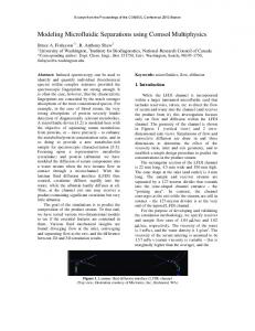
Electrochemical cell Geometry: In this geometry Cylindrical Anode is kept at left side and Cylindrical Cathode is at centre In this problem two electrodes and electrolyte was meshed with Triagonal elements.
Figure1: Electrochemical Cell
Figure5: Deposition Thickness Vs Time,
Figure6: Deposition Thickness Vs Time ,
Figure7: Deposition Thickness Vs Time ,
Ratio 0.3
Ratio 0.6
Ratio 1
FUTURE DIRECTION THEORY OF ELECTROREFINER MODELING
In this study, numerical analysis of an Electrorefiner was performed by using a commercial finite element method
Optimize the Cathode Surface Area For a Electrochemical Cell
code, namely, COMSOL Multiphysics software.
An electrodeposition secondary current distribution model was applied to evaluate the performance of a
Modeling of Multi electrode system for a electrodeposition using comsol Multiphysics
electrorefining cell, in particular the throughput and separation behavior. A moving mesh was used with the bulk density of Uranium dendrite. This approach should be useful to design a
Electrorefiner with suitable Anode surface area.
Figure8:
The Secondary current distribution interfaces set up the charge balance among the electrodes and electrolyte in
Deposition Thickness Vs Time, Ratio 2
Comparison of model developed by the comsol multiphysics with Experimental results
electrochemical cells. These balances are described under the assumption that the electrolyte composition is uniform. The interfaces define two independent variables, one for the potential in the electrolyte and another for the electric potential in the electrode. The conduction of current in the electrolyte is assumed to takes place through transport of ions , while electrons
CONCLUSION
Increasing the Ratio of Anode Surface Area to the Cathode Surface Area, increases the thickness of deposition that means that the rate of deposition increases
conduct the current in the electrode. For uniform electrolyte composition, the sum of the fluxes of all charged species yield the following expression for the current density vector:
REFERENCES
il = -σl ∇ ϕl
Where σl denotes the electrolyte conductivity and ϕl denotes the potential in the electrolyte. An analogous equation is defined by the interfaces for current conduction in the electrodes: is = -σs ∇ ϕs The rate of electrochemical reactions can be described by relating it to the activation overpotential. For an electrode reaction, with index m, the activation overpotential, denoted by ηm, is the following: ηm = ϕs – ϕl – Eeq,m
Where, Eeq,m denotes the equilibrium potential for reaction m.
Electrode Kinetics Expression: Butler-Volmer Equation :
iloc = i0 (exp (αaFη/RT) – exp (-αcFη/RT))
Where, iloc = Local current density, A/m 2
αa & αc = Anodic & Cathodic Charge Transfer coefficient, F = Faraday’s
constant, C/mol η = Overpotential, V R = Universal gas Constant, J/(mol K) T = Operating Temperature, K
1. Sungyeol Choi et al., “Three dimensional multispecies current density simulation of molten salt electrorefining,” J. Alloys and Compounds, 503,177-185 (2010) 2. K.R. Kim et al., “Multiphysics modeling of a molten salt electrolytic process for nuclear waste treatment”, Material science and Engineering, 9,012002 (2010) 3. Jun LI, “A Comprehensive Electrorefining Process Simulation Model for Pyroprocessing of spent Fuel”, proceedings of GLOBAL 2011 4. S.H. KIM, “Comparative Study on the primary and secondary current density distributions of Electrorefiner”, proceedings of GLOBAL 2011 5. K.R. Kim et al., “Multiphysics modeling of a molten salt electrolytic process for nuclear waste treatment”, Material science and Engineering, 9,012002 (2010) 6. S. Choi et al., “Uncertainty studies of real anode surface area in computational analysis for molten salt electrorefining”, Journal of Nuclear materials, 416,318-326 (2011) 7.B.Prabhakara Reddy et al., “Electrochemical studies on the redox mechanism of uranium chloride in molten salt LiCl-KCl eutectic”, Electrochimica Acta, 49,2471-2478 (2004) 8. Tsuguyuki Kobayashi, “Investigation of Cell Resistance for Moltensalt Electrorefining of Spent Nuclear Fuel”, Journal of Nuclear science and Technology, 32, 68-74 (1995)