ing algorithms play a fundamental role in nonblocking net- works, and any algorithm that ... ficient routing algorithms for these networks using parallel processing ...
Parallel Routing Algorithms for Nonblocking Electronic and Photonic Multistage Switching Networks Enyue Lu and S. Q. Zheng Department of Computer Science, University of Texas at Dallas, USA enyue, sizheng�@utdallas.edu Abstract Nonblocking multistage interconnection networks are favored to be used as switching networks whenever possible. Crosstalk-free requirement in photonic networks adds a new dimension of constraints for nonblockingness. Routing algorithms play a fundamental role in nonblocking networks, and any algorithm that requires more than linear time would be considered too slow for real-time applications. One remedy is to use multiple processors to route connections in parallel. In this paper, we study the connection capacity of a class of rearrangeable nonblocking and strictly nonblocking networks with/without crosstalkfree constraint, model their routing problems as weak or strong edge colorings of bipartite graphs, and propose efficient routing algorithms for these networks using parallel processing techniques.
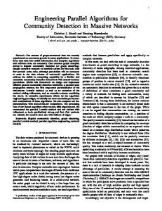
SE can have switching speed ranging from hundreds of picoseconds to tens of nanoseconds [15]. However, due to the nature of optical devices, optical switches hold their own challenges. One problem is crosstalk, which is caused by undesired coupling between signals carried in two waveguides so that two signal channels interfere with each other. Fig. 1 shows an example of crosstalk in an SE. Each SE has two logic states, namely, straight and cross (see Fig. 1 (a)). For the straight state, a small fraction of input signal injected at the upper input may be detected at the lower output (see Fig. 1 (b)). Crosstalk can also occur when an SE is in the cross state. Consequently, the input signal will be distorted at output due to crosstalk accumulated along connection path. Waveguide
Voltage
Input signal
Output signal Electrode
Straight
1
Introduction
Crosstalk Electrode Cross
Interconnection networks have many different applications, including but not limited to, being used as interconnects for communications among processors and between processors and memory modules in a multiprocessor or multicomputer system, and as a switching network within a network router or switch. Roughly speaking interconnection networks are classified into two classes, direct (routerbased) networks and indirect (switch-based) networks [3]. A typical indirect interconnection network is a multistage interconnection network (MIN). In this paper, we consider MINs in the context of their being used as switching networks. We investigate their ability of simultaneously realizing one-to-one I/O mappings in the form of permutations. A switching network usually comprises a number of electronic or photonic switching elements (SEs) grouped into several stages interconnected by a set of wires or optical links. A photonic switching network can be built from ¾ � ¾ electro-optical SEs such as common lithium-niobate (LiNbO¿) SE (e.g. [4, 5]). Each SE is a directional coupler with two inputs and two outputs. Depending on the amount of voltage at the junction of two waveguides, optical signals carried on either of two inputs can be coupled to either of two outputs. An electronically controlled optical
(a)
(b)
Figure 1. (a) States of an SE (b) Crosstalk in an electro-optical SE. According to blocking properties, Switching networks are classified as blocking and nonblocking. In an SE, if two active inputs (resp. outputs) intend to be connected with the same output (resp. input), it causes output link conflict (resp. input link conflict). Crosstalk in photonic switching networks adds a new dimension of blocking, called node conflict, which happens when an SE has two active inputs/outputs. In order to reduce blocking effect, one approach, called space dilation, has been proposed. In space dilation approach, blocking can be eliminated by ensuring at most one connection passing through a link for electronic switching networks (in which there is no crosstalkfree constraint) or through both a link and an SE for photonic switching networks (in which there is the crosstalkfree constraint). More specifically, blocking can be avoided
Proceedings of the 18th International Parallel and Distributed Processing Symposium (IPDPS’04)
0-7695-2132-0/04/$17.00 (C) 2004 IEEE
by increasing the number of SEs in a switching network (e.g. [8, 9, 14, 16, 17, 18, 19]). Nonblocking networks have been favored in switching systems since they can set up any one-to-one I/O mapping. There are three types of nonblocking networks: strictly nonblocking (SNB), wide-sense nonblocking (WSNB) and rearrangeable nonblocking (RNB) [1, 6]. In both SNB and WSNB networks, a connection can be established from any idle input to any idle output without disturbing existing connections. In SNB networks any of available conflict-free paths for a connection can be chosen and in WSNB networks, however, a rule must be followed to choose one. The high degree of connection capability in SNB and WSNB networks is at a high hardware cost. RNB networks, usually constructed with lower hardware cost, can establish a conflict-free path for the connection from any idle input to any idle output if the rearrangement of existing connections is allowed. A network is self-routing if any connection is established only by the addresses of its source and destination regardless of other connections. A self-routing network can be either blocking such as a Banyan network or nonblocking such as a crossbar. In a switching network, when more than one input requests to be connected with the same output, output contention occurs. Output contentions can be resolved by switch scheduling. For a set of connection requests without output contentions, the process of establishing conflict-free connection paths to satisfy these requests is called switch routing. A switch routing (or simply, routing) algorithm is needed to find these paths. Once a set of conflict-free paths is found, the SEs on these paths can be properly set up. Routing algorithms play a more fundamental role in WSNB and RNB networks since the nonblockingness depends on them. For SNB networks, routing algorithms tend to be overlooked, since a conflict-free path is always guaranteed for the connection from any idle input to any idle output without rerouting the existing connections. An efficient routing algorithm, however, is still needed to find such a conflict-free path for each connection request. Any routing algorithm requiring more than linear time would be considered too slow. Thus, finding efficient algorithms to speed up routing process is crucial for high-speed switching networks. Recently, a class of multistage nonblocking switching networks has been proposed. In this class each net�� �� �� ��, has relatively low hardwork, denoted by ware cost and short connection diameter, � � � �� � � and � �� � � respectively, in terms of the number of SEs1 . �� �� �� ��, � ��� ��, is constructed by horiA zontally concatenating � � �� � � �� extra stages to an � � � Banyan-type network and vertically stacking � copies of the extended Banyan. Networks �� �� �� �� and �� �� �� �� are similar in structure, but the latter does not allow any two connection paths through the same SE �� �� �� �� and �� �� �� �� are while the former does. suitable for electronic and optical implementation, respec�� �� �� �� can be SNB, tively. It has been shown that WNB and RNB with certain values of � and � for given � 1 In
this paper,
� �� (� �� � ) and all logarithms are in base 2.
and � [8, 9, 12, 17, 18]. Routing � connections sequen�� �� �� �� needs � � �� � � time. When the tially in number of connection requests becomes larger, the routing time complexity is greater than � � �. To the best of our knowledge, except for some special cases such as �� �� �� ��) and Benes network Banyan network (i.e., (i.e., �� �� � � �� �� ��), no effort of investigating faster routing for the whole class of these networks has been reported in the literature. In this paper, by examining the connection capacity of �� �� �� ��, we first model the routing problems for this class of networks as weak and strong edge colorings of bipartite graphs. Basing on our model, we propose fast �� �� �� �� using parallel prorouting algorithms for cessing techniques. We show that the presented parallel routing algorithms can route � connections in � � � �� �� �� � � �� � � time for an RNB �� �� �� �� and in � �� �� �� � � ����� ��� time for an SNB �� �� �� � ��. Since �� �� � � � � and � � �� � , the proposed algo� rithms can always set up � � � connections � in � �� � � time for RNB �� �� �� �� and in � � �� � � time for SNB �� �� �� � ��.
2
Nonblocking Networks Based on Banyan Networks
A class of multistage self-routing networks, Banyan-type networks, has received considerable attention. A network belonging to this class has properties of short connection diameter, unique connection path, and uniform modularity, which are very attractive for constructing switching networks. Several well-known networks, such as Banyan, Omega, Shuffle, and Baseline, belong to this class. It has been shown that these networks are topologically equivalent. In this paper, we use Baseline network as the representative of Banyan-type networks. An � � � Baseline network, denoted by � �, is constructed recursively. A � is a � SE. A � � consists of a switching stage of � SEs, and a shuffle connection, followed by a stack of two � �’s. Thus a � � has � � � stages labeled by �� � � � � ��� from left to right, and each stage has � SEs labeled by �� � � � � � �� from top to bottom. Each SE has two inputs, each named upper input or lower input if it is above or under the other, and two outputs, each named upper output or lower output similarly. The upper and lower outputs of each SE in stage are connected with two � �� �’s, named upper subnetwork and lower subnetwork, respectively. The � links interconnecting two adjacent stages and � � are called output links of stage and input links of stage � �. The input (resp. output) links in the first (resp. last) stage of � � are connected with � inputs (resp. outputs) of � �. To facilitate our discussions, the label of each stage, link and SE is represented by a binary number. Let � � � � � � be the binary representation of . We � to denote the integer that has the binary representause tion � � � � � � � � �. An example is shown in Fig. 2.
Proceedings of the 18th International Parallel and Distributed Processing Symposium (IPDPS’04)
0-7695-2132-0/04/$17.00 (C) 2004 IEEE
upper subnetwork BL(8) 0000 0001
P0 P1 I N P U T S
0010 0011 0100 0101 0110 0111 1000 1001 1010 1011 1100 1101 1110 1111
000 001 010 011 100 101 110 111
0000 0001
0000 0001
0010 0011
0010 0011
0100 0101
0100 0101
0110 0111
0110 0111
1000 1001
1000 1001
1010 1011
1010 1011
1100 1101
1100 1101
1110 1111
1110 1111
000 001 010 011 100 101 110 111
0000 0001
0000 0001
0010 0011
0010 0011
0100 0101
0100 0101
0110 0111
0110 0111
1000 1001
1000 1001
1010 1011
1010 1011
1100 1101
1100 1101
1110 1111
1110 1111
000 001 010 011 100 101 110 111
0000 0001
0000 0001
0010 0011
0010 0011
0100 0101
0100 0101
0110 0111
0110 0111
1000 1001
1000 1001
1010 1011
1010 1011
1100 1101
1100 1101
1110 1111
1110 1111
000 001 010 011 100 101 110 111
0000 0001 0010 0011 0100 0101 0110 0111 1000 1001 1010 1011
O U T P U T S
free constraint and � � if the network has crosstalkfree constraint. Clearly, � �� �� �� � is a Baseline network and � �� � �� �� � is a Benes network [1]. In � �� �� �� �, a subnetwork, denoted by � �� �� � �� � � (� � � � � �) is defined as a � � �� � � �� �� ��� �� � from stage � to stage � � �� �� �� �. Fig. 3 shows an example of � ��� �� �� �, which contains three planes of � ��� �� �� �, and each � ��� �� �� � contains two extra stages.
1100 1101 1110 1111
3 planes
2 extra stages
lower subnetwork BL(8) 0
1
STAGES
2
3
Figure 2. Self-routing connection paths and ½ in �� ���.
¼
Self-routing in �� � � is decided by the destination of each connection. If the � ��-th bit, � � ½, of the destination equals to �, the input of the SE that the connection path enters in stage � is connected to the SE’s upper output, and otherwise (i.e., � � ½ � �) to the lower output. Since two adjacent stages are connected by shuffle connection, the unique path for each connection can be derived. If Baseline network is used for photonic switching, it is a blocking network since two connections may pass through the same SE, which causes node conflict. Even if Baseline network is used for electronic switching, it is still a blocking network since two connections may try to pass through the same input (resp. output) link, which causes input (resp. output) link conflict. Fig. 2 shows two connection paths ¼ from ���� to ���� and ½ from ���� to ����. ¼ and ½ have the output link conflict in stage � and input link conflict in stage � because both two active inputs of SE � in stage � intend to be connected with its lower output and both active outputs of SE in stage � intend to be connected with its upper input; they have node conflicts at SEs � and in stages � and �, respectively. Although a Baseline network is blocking, a nonblocking network can be built by extending it in three ways: horizontal concatenation of extra stages to the back of a Baseline network, vertical stacking of multiple copies of a Baseline network, and the combination of both horizontal concatenation and vertical stacking [8, 9, 17, 18]. In the general approach, a network is constructed by concatenating the mirror image of the first � � �� stages of �� � � to the back of a �� � �, then vertically making copies of the extended �� � � (each copy is called a plane), and finally connecting the inputs (resp. outputs) in the first (resp. last) stage to � � � splitters (resp. � � combiners). Specifically, the �-th input (resp. output) of the -th plane is connected with the -th output (resp. input) of the �-th � � splitter (resp. � � combiner), which is connected with the �-th input (resp. output) of this network. We denote a network constructed in this way by � �� �� � �, where is crosstalk factor. That is, � � if the network has no crosstalk-
I N P U T S
0 1
0 1
2 3
2 3
4 5
4 5
6 7
6 7
8 9
8 9
10 11
10 11
12 13
12 13
14 15
14 15
0
1
2
3
4
O U T P U T S
5
STAGES
Figure 3. A network
3 3.1
�
� � � �.
�� � �
Graph Model I/O Mapping Graphs
Let � and � be the sets of � inputs, denoted by �¼ � � � � � �� ½, and � outputs, denoted by �¼� � � � � �� ½, of � �� �� � � respectively. For � �� �� � �, a set of � inputs (resp. outputs) is called the �-th modulo-� input group (resp. modulo-� output group) if the inputs (resp. outputs) in the set are congruent to � � when the modulus is � � �� � � � � � �). Let � � � � � � be an � � mapping that indicates connections from � to �. If there is a connection from �� to �� , then set � �� � and � ½ � � �; otherwise set � �� � �. If �� � �� for any �� , then set � ½ � � �. We say that an input (resp. output, link, SE)
is active if it is on a connection path, and idle otherwise. An I/O mapping from � to � is one-to-one if each �� is mapped to at most one �� and � �� �� � � for any � �� . In this paper, all I/O mappings are one-to-one and all connections belong to a one-to-one I/O mapping. If a connection path does not have any link (resp. node) conflict with other connection paths, it is called a link conflict-free (resp. node conflict-free) path. Clearly node conflict-free path is also link conflict-free, but the converse is not true. If a set of connections can be set up by conflict-free paths in � �� �� �� �, these connections are
Proceedings of the 18th International Parallel and Distributed Processing Symposium (IPDPS’04)
0-7695-2132-0/04/$17.00 (C) 2004 IEEE
called feasible connections of �� �� �� ��. Our goal is to quickly set up � link (resp. node) conflict-free paths for � connections of any I/O mapping in �� �� �� �� (resp. �� �� �� ��). To achieve this goal, we usually decompose a set of connections into disjoint subsets, and route each subset in one plane of �� �� �� �� so that each subset is feasible for its assigned plane. Given any I/O mapping with � connections for �� �� �� ��, we construct a graph � �� �� ��, named I/O mapping graph, as follows. The vertex set consists of two parts, ½ and ¾ . Each part has � � vertices, i.e., each modulo-� input (resp. output) group is represented by a vertex in ½ (resp. ¾ ). There is an edge between vertex � �� in ½ and vertex �� in ¾ if � ��. Thus, � �� �� �� is a bipartite graph with � � vertices in each of ½ and ¾ and � edges, where at most � edges are incident at any vertex. Thus, the degree of � �� �� ��, the maximum number of edges incident at a vertex, equals to �. Since there may be more than one connection from a modulo-� input group to the same modulo-� output group, � �� �� �� may have parallel edges between two vertices. However, there is a one-to-one correspondence between active inputs/outputs in the I/O mapping and edges in the I/O mapping graph, and thus, we can label each edge by its corresponding input. An edge � is called the left edge (resp. right edge) of edge if � � � (resp. �� � �). Any edge has at most one left edge and at most one right edge in � �� �� ��. Two edges � and are called neighboring edges if � is the left or right edge of . We define a component of � �� �� �� as follows: two edges � and � belong to the same component if and only if there is a sequence of edges � � �½ � � � � � � � � such that �� and ��·½ , � � � � � �, are neighboring edges. If every edge in a component has two neighboring edges, it is called a closed component; otherwise it is called an open component. It is easy to verify that each edge is in exactly one component, and thus, components are edge disjoint in � �� �� ��. In Fig. 4, (a) shows an I/O mapping with �� inputs, 25 of which are active; (b) shows the I/O mapping graph � ��� ��� � of (a), where each of ½ and ¾ of � ��� ��� � has vertices and each vertex includes inputs (resp. outputs) belonging to the same modulo- input (resp. output) group; (c) shows all components of � ��� ��� � in (b).
3.2
Graph Coloring and Nonblockingness
If we set up connections in �� �� �� �� one by one by sequential algorithms, the time complexity for establishing � connections is � � � � � ��� since it takes � � � �� time to set up one connection. For a large number of connections, the time required is more than � � �, which is not acceptable for real-time applications. Parallel processing techniques can be used to speed up rout�� �� �� ��. We say that two connections share ing in a modulo-� input (resp. output) group if their sources (resp. destinations) are in the same modulo-� input (resp. output) group. Let us study the connection capability of �� �� �� �� first.
Lemma 1 For any connection set � of �� �� �� ��, if no two connections in � share any modulo-� input (resp. output) group, then the connection paths for � satisfy the following conditions: (i) they are node conflict-free in the first (resp. last) � stages; (ii) they are input link conflict-free in the first � � � (resp. last �) stages and output link conflict-free in the first � (resp. last � � �) stages. Lemma 2 For any pair of input and output in �� �� �� ��, there are �� paths connecting them. It is easy to verify that Lemmas 1 and 2 are true according to the topology of � � � (refer to [12] for formal proofs). Using the above two lemmas, the following claim can be easily derived from the results of [12].
�� �� �� ��, if Lemma 3 Given a connection set � of any two connections in � do not share any moduloÒ Ü·« � ¾ � input group and also do not share any Ò Ü·« modulo-� ¾ � output group, then � is feasible for �� �� �� ��. By Lemma 3, if we assign the connections of with sources (resp. destinations) passing through the same modulo-� input (resp. output) group to different planes, then we can route connections in �� �� �� �� without conflict. Thus, in order to set up �� �� �� ��, we first need conflict-free connections in to determine which plane to be used for each connection. By constructing an I/O mapping graph � �� �� �� with � � � Ò Ü¾·« � , we can reduce the problem of routing � connections in �� �� �� �� to the following two graph coloring problems: Weak Edge Coloring Problem (WEC problem): Given an I/O mapping graph � �� �� �� with �¼ � � � colored edges, color � edges with a set of colors such that no two edges with the same color are incident at the same vertex of � �� �� �� with the changing of the colors of the �¼ colored edges allowed. If we can find a weak edge coloring of � �� �� �� using �½ different colors, we call this coloring a (weak)2 �½ -edge coloring of � �� �� ��. Strong Edge Coloring Problem (SEC problem): Given an I/O mapping graph � �� �� �� with �¼ � � � colored edges, color � � �¼ uncolored edges with a set of colors such that no two edges with the same color are incident at the same vertex of � �� �� �� without changing the colors of the �¼ colored edges. If we can find a strong edge coloring of � �� �� �� using �¾ different colors, we call this coloring a strong �¾ -edge coloring of � �� �� ��. If we think the colored (resp. uncolored) edges in � �� �� �� as the existing (resp. new) connections in �� �� �� ��, a solution to the ��� problem is a plane assignment for routing in an RNB network since we can reroute existing connections in such a network, and a solution to the ��� problem is a plane assignment for routing in an SNB network since rerouting existing connections is not allowed in such a network. Clearly, for the same � �� �� ��, �½ � �¾ .
�� �� �� ��
2 The definition of weak edge coloring is the same as the definition of edge coloring in graph theory. Thus we omit “weak” in the following of paper.
Proceedings of the 18th International Parallel and Distributed Processing Symposium (IPDPS’04)
0-7695-2132-0/04/$17.00 (C) 2004 IEEE
4 4.1
Routing for Rearrangeable Nonblocking Networks Rearrangeable Nonblockingness
Ò Ü·« Lemma 4 If ¾ ¾ � , then � �� �� � �� is rearrangeable nonblocking.
The above claim is implied by the results of [12]. It is important to note that the minimum value of in Lemma 4 equals to the value of � in Lemma 3, where is the number of � �� �� �� �� planes required for � �� �� � �� to be rearrangeable nonblocking. By Lemmas 3 and 4, if we assign the connections (including existing and new connections) sharing the same modulo-� input/output group to different planes, the connections are feasible for every assigned plane. Then, the routing can be completed by setting up conflict-free connection paths within each plane. Lemma 5 Every bipartite graph � has a �-edge coloring, where � is the degree of �. Ò Ü·« By Lemma 5 (see a proof in [2]), if we set � � � ¾ � in � �� �� ��, the plane assignments for a set of connections in RNB � �� �� � �� can be solved by finding a �edge coloring of � �� �� �� since the degree of � �� �� �� equals to �.
4.2
Algorithm
� �� �� ��
for
Balanced
�-Coloring
of
In order to solve � problem efficiently, we present an algorithm for a problem, named balanced 2-coloring problem: given an I/O mapping graph � �� �� ��, color its edges with � colors so that every vertex is adjacent to at most � � edges with one color and � � with the other. We choose to present our parallel algorithms for a completely connected multiprocessor system since any algorithm for this parallel computing model can be easily transformed to algorithms on more realistic multiprocessor systems. A completely connected multiprocessor system of size � consists of a set of processing elements (PEs) , � � � � � � �, connected in such a way that there is a connection between every pair of PEs. We assume that each PE can communicate with at most one PE during a communication step. Initially, each PE reads � �� from input �, sets value of ��½ in PE�´ µ as �, and then performs the following two steps. Step 1. Divide the I/O mapping graph � �� �� �� into a set of components. This step can be done by each edge finding its left edge �� and right edge ��½ � ���. Step 2. Color components with two colors, red and blue, so that neighboring edges in each component have different colors. Each component has two specific representatives, simply referred to Rep’s. (There is an exception: for the component
with length of �, there is only one Rep, which is itself.) For closed and open components, the Rep’s are defined differently. For a closed component, we define two edges with the minimum labels as two Rep’s; for an open component, if an edge � has no left edge or �’s left edge has no right edge, � is defined as one Rep. Fig. 4(c) shows the Rep’s of all possible types of components, where the Rep’s of each component are marked as dark lines and edges are labeled by their corresponding inputs Step 2 can be done by coloring edges with the Rep’s as references using the pointer jumping technique in [7]. At the beginning, each edge sets its pointer to point to the right edge of its left edge if it exists and to itself otherwise. By doing so, for a closed component or an open component with more than one edge, two disjoint directed cycles or paths are formed, each containing a Rep. For an open component, furthermore, the end pointer of every directed path is pointing to one of the Rep’s. For example, Fig. 4(d) shows that the directed cycles and paths formed from the components of Fig. 4(c). Then, by performing �� �� ��� times of parallel pointer jumping, each edge finds the Rep belonging to the same directed cycle or path. Finally, each edge can be colored by comparing the value of the Rep found by itself with that by its neighbor. That is, if the value of the Rep founded by an edge is no larger than its neighbor’s, color the edge with red; and otherwise color it with blue. Fig. 4(b) shows a balanced �coloring of an I/O mapping graph of Fig. 4(c), where solid lines are colored as red and dashed lines are colored as blue. Theorem 1 A balanced �-coloring of any � �� �� �� can be found in � � � � time using a completely connected multiprocessor system of � PEs. Proof. Given an I/O mapping graph � �� �� ��, Step 1 can be done in � �� time using a completely connected multiprocessor system of � PEs. In Step 2, since the length of each directed cycle or path is at most �� ��, each edge can find a Rep by �� �� ��� times of pointer jumping. Clearly, all edges in the same directed cycle or path are colored with the same color since they find the same Rep. The pointer initialization implies that each edge and its neighboring edge are in different directed cycle or path, and thus, they have different colors. By the definition of left/right edge, there are no more than � � pairs of neighboring edges incident at any vertex of � �� �� ��. Thus, the coloring of all components compose a balanced �-coloring of � �� �� ��. Therefore, a balanced �-coloring of any � �� �� �� can be found in � � � � time. ¾
4.3
Algorithm for �-Edge Coloring of � �� �� ��
Based on the balanced 2-coloring algorithm, a � solution to any I/O mapping graph � �� �� �� with no more than � colors can be found as follows. Initially, we remove all colors for �¼ already colored edges. In initial step (i.e., step 0), we find a balanced 2-coloring of � �� �� �� using colors � and �, and let �¼ and �½ be the graphs induced by the edges with colors � and �, respectively. In step 1, if the degree of �¼ and/or �½ is no less than �, we find a balanced 2-coloring for �¼ using colors �� and ��, and/or
Proceedings of the 18th International Parallel and Distributed Processing Symposium (IPDPS’04)
0-7695-2132-0/04/$17.00 (C) 2004 IEEE
i
π (i)
0 1 2 3 4 5 6 7 8 9 10 11 12 13 14 15 16 17 18 19 20 21 22 23 24 25 26 27 28 29 30 31
6 10 -1 0 4 -1 -1 3 11 26 12 22 5 16 9 20 -1 -1 1 28 23 30 21 24 7 27 29 -1 17 15 -1 25
(a)
V1
G(32, 25, 8)
V2
0 1 2 3 4 5 6 7
0 1 2 3 4 5 6 7
8 9 10 11 12 13 14 15
8 9 10 11 12 13 14 15
16 17 18 19 20 21 22 23
16 17 18 19 20 21 22 23
24 25 26 27 28 29 30 31
24 25 26 27 28 29 30 31
3
0 1
4
10 11
18 19
8 9 24 25
14
12 13
15 22 23
20 21
26
7
28 29
(i) 1 closed component
31
(ii) 5 open components (c)
0
1
3
10
8
18
11
9
19
20
25
26
21
4
14
12
15
13
7
22
28
23
29
31
24 (d)
(b)
Figure 4. Finding a balanced ¾-coloring (a) An I/O mapping (b) A balanced ¾-coloring of an I/O mapping graph ��� ��� �� (c) A set of components (d) Pointer initialization for pointer jumping.
find a balanced 2-coloring for ½ using colors �� and ��. This process is recursively continued in a binary tree fashion until a solution to WEC is reached. More formally, in � � �, we find a balanced each recursive step �, � using colors � � and � � (i.e., 2-coloring for each graph is no less concatenate � or � with � ) if the degree of than �, where � is a binary representation of an integer in ��� �� � � � � �� � �� and the color of � � in step � � �. Theorem 2 For any I/O mapping graph �� �� ��, a �edge coloring can be found in � � � � � � � time using a completely connected multiprocessor system of � PEs.
�� �� ��. Since Proof. There are � ( � ) edges in � �� , we can prove the theorem by an induction on . If �, it is true since a balanced �-coloring is a �-edge coloring by Theorem 1. Assume that for any � , the theorem holds. Now, we prove that the theorem holds for �. First, we find a balanced �-coloring of �� �� ��, which can be done in � � � � time by Theorem 1. Let ¼
and ½ be the graphs induced by the edges of two different colors from this balanced �-coloring. By the definition of balanced �-coloring, we know that � ¼� � � and � � �. By the hypothesis, we can find a � ��½� edge coloring for each of ¼ and ½ in � � �� � � � � time on a completely connected multiprocessor system of �� ¼�� and �� ½�� PEs, respectively, which can be carried out simultaneously since � ¼� � � ½� �. The � ��-edge colorings of ¼ and ½ compose a �-edge coloring of �� �� ��, which takes total � � � � � time for a completely connected multiprocessor system of � PEs.
¾
4.4
Parallel Routing in a Plane
We have shown how to assign a plane to each connection in an RNB � �� �� �� ��. In this section, we show how connections are routed within each plane. Lemma 6 Let � be a set of feasible connections for � �� �� �� ��. If each connection in � is set up in the first and last � stages such that the output link in stage � and the input link in stage � � � � on each connection are connected with the same subnetwork � �� �� � ��·½� ��, � � � � �, then � can be routed by self-routing in the middle � � � � stages. Proof. By the topology of � �� �� �� ��, we know that each connection must pass through the same subnetwork � �� �� � ��� ��, � � � � � �. Since the middle � � � � stages of � �� �� �� �� consists of �� Baseline network �� ¾�Ü �, this lemma is true. ¾ Theorem 3 Let � be a set of � feasible connections of � �� �� �� ��. Then � can be correctly set up in � � � � � � � time using a completely connected multiprocessor system of � PEs. Proof. By Lemma 6, what we only need to do is to set up � correctly in the first and last � stages for � � �. By the topology of � �� �� �� ��, we know that the output link in stage � and the input link in stage � � � � on each connection are connected with the same subnetwork � �� �� � ��·½� ��, � � � � �. Thus, we need to decide which subnetwork to be used for each connection
Proceedings of the 18th International Parallel and Distributed Processing Symposium (IPDPS’04)
0-7695-2132-0/04/$17.00 (C) 2004 IEEE
since there are ¾ �� �� ��� � ��’s. This can be reduced to a �-edge coloring of a bipartite graph with degree of �. For each subnetwork �� �� ��� � ��, � � � � �, we construct an I/O mapping graph � ��� � � � ��, where � is the number of connections passing through it. We color the edges of � ��� � � � �� with two different colors and assign the connections (edges) with the same color to pass through the same subnetwork �� �� ��� ·½� ��. Specifically, in each step �, � � � � �, we run -edge coloring algorithm for � � ��� � � � ��’s with � �. By Theorem 2, each step can be done in �� � � time. Thus, the time to set up � feasible connections in the first and last � stages is � �� � �. By Lemma 6, we can set up the connections in the middle �� � � � stages by self-routing, which takes �� � � � time. Therefore, the total time to route � feasible connections of �� �� �� �� is � �� � � �� � � using a completely connected multiprocessor system of � PEs. ¾
4.5
Overall Routing Performance
Theorem 4 For any RNB �� �� �� �� , we can correctly route � connections (including existing and new connections) in � � �� �� �� � � �� � � time using a completely connected multiprocessor system of � PEs. Proof. By Theorem 2, we can find a �-edge coloring of the I/O mapping graph � �� �� �� in �� � �� � � time. By Lemma 3, we assign the connections with the same color to �� �� �� ��, by Theorem the same plane. In each plane 3, we can set up the connections in � �� � � �� � � time. Thus, the total time complexity is � ��� �� �� � ��� � �.
¾
By Theorem 4, the routing time for setting up � � connections in an RNB �� �� �� �� is improved to � � �� �� �� � � �� � � from � � � � �. By Lemma 4, for an RNB �� �� �� �� and an RNB �� � �� �� ��, the minimum number of planes of Baseline network and Benes Ò·« ½·« network, equals to � ¾ � and � ¾ � , respectively. Consequently, we can route connections in ��¾ � � time for both �� �� �� �� and �� � �� �� ��. For the RNB �� � �� �� ��, which is the electronic Benes network, this performance is the same as the best known results reported in [11, 13].
5 5.1
Routing for Strictly Nonblocking Networks Strict Nonblockingness
The following lemma can be easily derived from the results of [18]. Lemma 7 If
�� then
�
��� � � ÒÒ ¾ ÜÜ·½¿¾ � ½¾ �� � �� ½ � � ��� � � ¾ � � ¾ �� � �� ��
�� �� �� �� is strictly nonblocking.
for even � � for odd � �
For an SNB network, we can set up new connections (as long as these connections form an I/O mapping from idle inputs to idle outputs) without disturbing the existing ones; however, this routing problem is by no means to be simpler than that in an RNB network when we need to set up the new connections simultaneously. In this section, we present a parallel algorithm based on graph coloring to speed up routing time. Based on the discussions in Section 3, we know that the �� �� �� �� can be solved routing problem for an SNB by finding a strong edge coloring of the I/O mapping graph � �� �� � with � � Ò Ü¾·« � . Lemma 8 Any graph � has a strong ing, where � is the degree of �.
��
� ��-edge color-
Proof. Consider coloring edges in an arbitrary order. Since each edge in � is adjacent to at most �� � � edges, any uncolored edge in � can always be assigned a color so that the total number of colors used is no more than �� � �. ¾ We consider a subclass of SNB networks, �� �� �� � �� Ò·« with �� � � ¾ �·½ � �. By Lemma 7, we know that � �� �� �� � �� is an SNB network. Since each plane of �� �� � � �� is a Baseline network, the routing of connections in any plane can be done by self-routing. Thus, the problem of setting up connections in �� �� �� � �� is reduced to finding a plane for each new connection so that all connections, including existing ones, are conflict-free. By Lemmas 3 and 8, this can be done by finding a strong � � ��-edge coloring for � �� �� � of �� �� �� � �� with �¼ existing connections and � � �¼ new connecÒ·« tions, where � � ¾ � . In the next subsection, we present an algorithm to find a strong � � ��-edge coloring of � �� �� �.
5.2
Algorithm for Strong of � �� �� �
� ��-Edge Coloring
�
A matching is defined as a set of edges that does not contain any adjacent edges. Conceptually, a strong � � ��edge coloring of � �� �� � with �¼ � � colored edges can be done in the following two steps. Step 1: find a set of matchings in � �� � � �¼ � �; Step 2: color matchings one by one without changing the existing colors. It is easy to see that the edges with the same color compose a matching for any -edge coloring of � �� � � �¼ � �. Thus, Step 1 can be done by finding a -edge coloring of � �� � � �¼ � �, which divides � � �¼ uncolored edges (corresponding to new connections) into at most matchings. By Theorem 2, it takes �� � �� � � �¼ �� time using a completely connected multiprocessor system of � PEs. In � �� �� �, each edge is adjacent to at most � � � edges, and hence, there are at most � � � colored edges adjacent to each edge in a matching. Thus we can color every edge in the matching by one of the unused colors. This can be done by parallel searching for a free color among � � � colors, which takes �� � time. Since no
Proceedings of the 18th International Parallel and Distributed Processing Symposium (IPDPS’04)
0-7695-2132-0/04/$17.00 (C) 2004 IEEE
two edges are adjacent in a matching, by coloring match��-edge colings one by one in � �� �� �, a strong � oring of � �� �� � is found. Therefore, we have the following claim. Theorem 5 For any I/O mapping graph � �� �� � with � � � � colored edges, a strong � ��-edge coloring can be found in � �� �� � � � � �� � time using a completely connected multiprocessor system of � PEs.
5.3
Performance Analysis
Theorem 6 For a strictly nonblocking network Ò·« �, we can estab� �� �� �� � with � � � ¾ ��� lish � connections from � idle inputs to � idle outputs in � �� � �� � � � �� �� time using a completely connected multiprocessor system of � PEs. Proof. In � �� �� ��, we assume the edges corresponding to the existing connections in the -th plane of � �� �� �� � have been colored with color and the edges corresponding to the new connections have not been colored yet. By Theorem 5, we can find a strong �� ��-edge coloring of � �� �� �� in � �� � �� � � � �� �� time using a completely connected multiprocessor system of � PEs. We assign each new connection with color to the -th plane of � �� �� �� �. By Lemma3, these new connections can be ¾ set up by self-routing in � �� � � time. By Lemma 7, we can derive the minimum number of planes, ���� , in � �� �� �� �. Compared with � �� �� ���� � �, the hardware redundancy of � �� �� �� � � is shown as follows. �
�
�� ���� �� ���� � �� ��� �� ��
if � � and � is odd if � � and � is even if � � and � is even if � � and � is odd
The hardware cost of � �� �� �� � �, in terms of the number of SEs, is higher than that of � �� �� ���� � � in half of the cases, but both have the same hardware complexity of � � � �� � �. The routing time for setting up � � � � connections, however, is improved to sublinear � � �� � � from � �� � �.
6
Concluding Remarks
One major contribution of this paper is the design and analysis of parallel routing algorithms for a class of nonblocking switching networks, � �� � �� �’s. Although the assumed parallel machine model is a completely connected multiprocessor system of � PEs, the proposed algorithms can be transformed to algorithms for more realistic parallel computing models. The pointer jumping and binary searching, which dominate the complexity of the proposed algorithms, can be reduced to sorting on realistic parallel computing structures. It is interesting to note that the sorting can be implemented in Banyan-type network in
� ��� � � time [10]. Thus the proposed algorithms can set up connections in � �� � �� � with a slow-down factor � ��� � � on a Banyan-type network, whose complexity is no larger than one plane of � �� � �� �.
References [1] V.E. Benes, Mathematical Theory of Connecting Networks and Telephone Traffic, Academic Press, New York, 1965. [2] J.A. Bondy and U.S.R. Murty, Graph Theory with Applications, Elsevier North-Holland, 1976. [3] J. Duato, S. Yalamanchili and L. Ni, Interconnection Networks - A Engineering Approach, Morgan Kaufmann, 2003. [4] H. Hinton, “A Non-Blocking Optical Interconnection Network Using Directional Couplers”, Proc. of IEEE Global Telecommunications Conference, pp. 885-889, Nov. 1984. [5] D.K. Hunter, P.J. Legg, and I. Andonovic, “Architecture for Large Dilated Optical TDM Switching Networks”, IEE Proc. on Optoelectronics, vol. 140, no. 5, pp. 337-343, Oct. 1993. [6] F.K. Hwang, The Mathematical Theory of Nonblocking Switching Networks, World Scientific, 1998. [7] J. Jaja, An Introduction to Parallel Algorithms, AddisonWesley, 1992. [8] C.T. Lea, “Multi-log2N Networks and Their Applications in High-Speed Electronic and Photonic Switching Systems”, IEEE Trans. on Communications, vol. 38, no. 10, pp. 17401749, Oct. 1990. [9] C.T. Lea and D.J. Shyy, “Tradeoff of Horizontal Decomposition Versus Vertical Stacking in Rearrangeable Nonblocking Networks”, IEEE Trans. on Communications, pp. 899-904, vol. 39, no. 6, June 1991. [10] F.T. Leighton, Introduction to Parallel Algorithms and Architectures: Arrays � Trees � Hypercubes, Morgan Kaufmann Publishers, 1992. [11] G.F. Lev, N. Pippenger and L.G. Valiant, “A Fast Parallel Algorithm for Routing in Permutation Networks”, IEEE Trans. on Computers, vol. 30, pp. 93-100, Feb. 1981. [12] G. Maier and A. Pattavina, “Design of Photonic Rearrangeable Networks with Zero First-Order Switching-ElementCrosstalk”, IEEE Trans. on Communications, vol. 49, no. 7, pp. 1268-1279, Jul. 2001. [13] N. Nassimi and S. Sahni, “Parallel Algorithms to Set Up the Benes Permutation Network”, IEEE Trans. on Computers, vol. 31, no. 2, pp. 148-154, Feb. 1982. [14] K. Padmanabhan and A. Netravali, “Dilated Network for Photonic Switching”, IEEE Trans. on Communications, vol. COM-35, no. 12, pp. 1357-1365, Dec. 1987. [15] R. Ramaswami and K. Sivarajan, Optical Networks: A Practical Perspective, second edition, Morgan Kaufmann, 2001. [16] F.M. Suliman, A.B. Mohammad, and K. Seman, “A Space Dilated Lightwave Network-a New Approach”, Proc. of IEEE 10th International Conference on Telecommunications (ICT 2003), vol. 2, pp. 1675-1679, 2003. [17] M. Vaez and C.T. Lea, “Wide-Sense Nonblocking BanyanType Switching Systems Based on Directional Couplers”, IEEE J. on Selected Areas in Communications, vol. 16, no. 7, pp. 1327-1332, Sep. 1998. [18] M. Vaez and C.T. Lea, “Strictly Nonblocking DirectionalCoupler-Based Switching Networks under Crosstalk Constraint”, IEEE Trans. on Communications, vol. 48, no. 2, pp. 316-323, Feb. 2000. [19] J.E. Watson et al., “A Low-Voltage � Ti:LiNbO¿ Switch with a Dilated Benes Architecture,” IEEE J. of Lightwave Technology, vol. 8, pp. 794-800, May 1990.
Proceedings of the 18th International Parallel and Distributed Processing Symposium (IPDPS’04)
0-7695-2132-0/04/$17.00 (C) 2004 IEEE