We call the trellis at the highest layer a. âsuper-trellis ..... Breaking the ACS-bottleneck,â IEEE Trans. ... Almaden Research Center between 1989 and 1990,.
IEEE TRANSACTIONS COMMUNICATIONS, ON
62
VOL. 41, NO. 1, JANUARY 1993
Parallel Viterbi Decoding Methods for Uncontrollable and ControllableSources Horng-Dar Lin, Member, IEEE, and David G. Messerschmitt, Fellow, ZEEE
Absrruct-ThefastestconventionalViterhidecodingmethod processesall states in parallel,but still decodescodesymbols sequentially.Inordertodecode faster than this rate,parallel methods must be developedto break the processing into independent state-parallel decoding tasks. This paper discusses parallel Viterbi decoding for two different cases: uncontrollable sources and controllablesources. For general,uncontrollableMarkov processes,weextendapreviouslyknownparallelmethodtoa hierarchical parallel decoding approach, which achieves a lower latency. For controllable Markov sources in telecommunications applications, we propose new parallel decoding methods by controllingthe source processesinappropriateways.Thispaper focuses on the parallel decoding methods for controllable sources because these methods have zero processing overhead. Because themethodsmodifythecodingprocess,theybringpositive changes to framing and negativechanges to latencyandcode performance.However,wecanadjusttheparametersofthe methodstomakethedegradationnegligible.Becauseoftheir lowoverhead,themethodsaremostattractiveforhigh-speed decoders for convolutional and trellis codes, and also applicable to other sequentialalgorithmsforsuboptimal decoding and estimation of complex Markov sources.
I. INTRODUCTION
T
HE Viterbi algorithm (VA) [l]applies the dynamic programming principle to the dctection of discrete-time finite-state Markov processes with a noisy observation, including decoding continuous phase modulated signals [2], [3], decoding of convolutional codes and trellis codes [4], [SI,and decoding signals in magnetic channels, or channels with intersymbol or interchannel interfcrence. The algorithm has been shown [6], [7] to be the maximum-likelihood (ML) sequence estimator for these applications. The VA has a fundamental speed limitation. The VA modcls possible state sequences of the source Markov process as paths in thc trellis, which represents states at different time indices as nodes in different trellis stages and state transitions as arcs between nodes. (See [l] for more detail). The core process of the VA involves selecting a minimal-metric path leading to each state, stage by stage. The path selection depends on the survivors and the survivor metrics of the previous trellis stage, and this data dependency limits the number of code symbols the VA decodes per second, or VA’s throughput. For example, Paper approved by the Editor for Coding Theory and Applications of the IEEE Communications Society Manuscript received January 20, 1989; revised August 5, I Y Y I . This paper was presented in part at ICC’89, Boston, MA. H:D. Lin is with AT&T Ball Laboratories, Holmdel. NJ 07733. 0.G . Messerchmitt is with the Department of Electrical Engineering and Computer Science, University of California at Berkeley, Berkeley, CA 94720. IEEE Log Number 9203587. ‘This throughput definition does not include the initial delay of the VA, but rather refers to the steady-state decoding spccd of the VA.
the VA can maximize its throughput by selecting minimalmetric paths for all states in parallel, because path selcctions for different states in the same stage are mutually independent. If 7 denotes the processing time for a state, the throughput of a state-parallcl implementation, or the throughput upper bound, is 1 / r symbols per second. The 1 / bound ~ originates from data dependency of the VA, and thus qualifies as a general bound to any conventionallyimplemented VA. For example, the methods in [8]-[10] use different ways of mapping the VA to VLSI architectures, but since the data dependency remains unchanged, the throughput bound is the same. To bypass the l/r throughput bound, we must modify the data dependency so that a state-parallel VA processor can simultaneously compute several stages of trellis. To achieve this, we have two alternatives. First is to consider path selections for multiple trellis stages and change the computational sequence or structure of these multistage path selections. If the new computational sequence or structure requires a shorter processing time, usually at the expense of additional hardwarc, we achievea speedup. Similar linear-complexity methods2 based on this approach have been proposed independently [11]-[14]. In Section 11, we extend the basic method in [13], [14] using a more general computational hierarchy. The advantage of the method is that it has a shorter processing latency. The previous approach, parallel decoding by changing the computation structure, seems to be general. However, its complexity overhead is proportional to the amount of the speed and alsoto the number of states. If we want to speed up the throughput significantly, the hardware overhead becomes unacceptably high. Similarly, this approach is not suitable for parallel decoding for sources with a large state space. Therefore, this approach is limited by its complexity overhead. The other approach to parallel decoding is to relax dependency betwccn decoding of different codesymbols so that we can break the decoding process into independent tasks. Several low-complexity methods have been proposed [15], [16] especially for telecommunication applications and will be summarized in the following. The parallel method in [IS], [25] is suitable for decoding applications with the convergence property. That is, the method assumes that when decoded fromawrong initial state, a survivor path converges to the right path after a finite length of ’Linear complexity means that thc complexity of the method is proportional to the speed improvement.
009M778/93$03.00 0 1993 IEEE
LIN AND MESSERSCHMITT:PARALLEL VITERBI DECODING METHODS
63
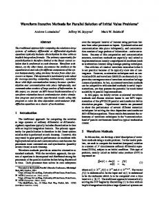
trellis (forward convergence).The method also assumes that all survivor paths originate froma commonpath some stagesback (backward convergence). Using the convergence property, the decoderindependentlydecodesdifferentsegments of code symbols from an arbitrary state, finds the survivor paths within the segments, and retains part of the paths that converge to thecorrectones. Errors happen when the selectedpaths do not converge to the correct ones within the expected time of convergence. The overhead of the method is proportional to the time of convergence, and therefore can be significant for codes with slow convergence rates. The method in [16]ismoreeffectivebecauseituses I,.\ is,decoding. parallel That interleaved [17]-[20] for coding \’I the data stream from an information source is interleaved into Fig. 1. An example trellis at (a) layer one, (b) layer two, and (c) layer three independentencoders, and then recombinedthroughmultiwhere L = 3, M I = 4, and hf2 = 3. plexing.Thereforethecombinedencodedsequenceiscomposed ofindependentsubstreamswhichcan be decoded in 11. PARALLEL DECODING FOR UNCONTROLLABLESOURCES parallel. The interleavedmethod can achieveanarbitrary speedup without overhead but not without other limitations. Here we define a few terms for the convenience of descripTo use the interleavedmethod, the encoder has to antici- tion. We define the number of trellis stagcs (or code symbols) pate an appropriatevalue of speedup,thuspredetermining that can be processed independently as the concurrency level the maximumthroughput at source.Thismakestheinterof the decoding method. The conventionalVA implementation leaved methodinappropriateforvariable-rateapplications. processes the trellis stageby stage [I], and thus its concurrency For example,instore-and-forwardcommunicationnetworks levelis 1. In principle,theconcurrencylevel of a method with time stamps, a decoder may haveto meet a certain defines how much faster the method is than the conventional deadline for processing a specificmessage or datapacket. implementation. For example, if a decoding method processes The requiredthroughput may exceedthedynamicrange of three stages of trellis simultaneously, with similar computathe decoderthroughput if theinterleaved method isused. tional complexity per stage, the methodruns three times faster, Anotherlimitation to the method is that interleavedcoding or has a speeedup of 3. may be infeasible in applications like decoding for continuous- As described in the introduction, modifying the computation phasemodulations and channelswithinter-symbolinterferstructure of the VA may improve the decoding throughput. We ence. develop a general, hierarchical VA implementation [13], [14] in which generates concurrency exactlyin this way. The methods Because of the limitation of thepreviousmethods, adopt a similar but Section 111, we propose two new methods to break the decod- in [ll], [12],developed inde~endently,~ ingprocessintoindependenttasks for controlluble Markov lessgeneralapproach. Consider the hierarchical method for the example in Fig* 1, sources. By controllable we mean eithertheinput to the wherethestatesize or the memory of theMarkovsourceis S of the trellisis 4. First,breakthe Markovsource externally (periodically) accessible. For example, for general original trellis into segments of M I stages each, as illustrated finite-state-machineencoders, our methodschangeonlythe in Fig. l(a) for A41 = 4. Thenforeachsegment, use the input to the encoders or the memory content (initial state) of VA to find the minimal-metricpaths between eachpossible the encoder, but not the state transition function or the output beginning and ending state of the segment. This can be donc, function. The majoradvantage of our methods is that they for example, by running a conventional Viterbi algorithm S times,each fora differentbeginningstatewith the initial do not incurprocessingoverheads. In Section IV, wewill to show that they haveothersidebenefitswhichmake them metric of that beginningstateset to zeroandallothers attractivesystem-lcvelsolutions.Anotheradvantage of our infinity. Then the final survivors at the end of trellis segments methods, pointed out in the conclusion, is that they apply to contain the minimal-metric paths starting from that beginning state. In practice,wecandecideallminimal-metricpaths other sequential decoding algorithms as well. within the segments in one pass of the VA by tagging metrics Thispaperfocusesmostly on the parallelmethodsfor controllable Markov sources, because they can provide a very with corresponding beginning states. Next, construct a new trellis at a higher layerby representing high throughputimprovementfordecodingcomplexcodes I1 the minimal-metric paths of the MI-stage trellis as branches. with very littleoverhead. Our generalmethodinSection Specifically, connect each possible pair of beginning and endrequires a lower latency but still a significant overhead like othergeneralmethods[11]-[14], and thereforeshould be ing state of the minimal-metric paths with a branch, as shown in Fig. l(b). Set the associated branch metric of the branch used only for uncontrollablesources. For simplicity,this of theminimal-metric path of the paper addresses mostly decoding applications of the VA, and to thepathmetricvalue same beginning and ending state, and thc associated “output inparticular,decodingforconvolutional and trelliscodes. Extensions to othercodes and applicationsarepossible but 3Altemativr derivatlon of these methods from the VA formulation in [SI will not be elaborated here. and the results in [26],[27] is alao possible.
IEEE TRANSACTIONS ON COMMUNICATIONS, VOL. 41, NO. 1, JANUARY 1993
64
The advantage of the general hierarchical method over the symbol” of the branch to the content of the minimal-metric path, i.e., thesurvivor.Atthenextlayer of thehierarchy, fixed two-layer hierarchy methods[ l l ] , [ 121 is the flexibility in we concatenate M2 stages of the new trellis to yield a single adjusting processing delay. For example, a two-layer method in segment. Again we find the minimal-metric paths within the with a speedupcomparable to thethree-layerhierarchy new trellis segment, and construct another trellis at the next Fig. 1 requires the segnlcnt length be M I = 12. The processhigher layer, as illustrated in Fig. l(c) for MZ = 3. The process ing delay is the timeforproccssing 12 stages of first-layer repeats until the highest layer, where we do not segment the trellis(sequentially) and for 1 stage of second-layertrellis, trellisfurther, but rather use the conventional VA to select a total of 13 units. In contrast, the three-layer hierarchy can paths stage by stage. We call the trellis at the highest layer a minimizedelay by processingsegmentsinparallel, and the “super-trellis,” because the trellis is compressed from minimal-processing delay is for 4 stages of first-layer trellis, 3 stages of second-layer trellis, and 1 stage of third-layer trellis. The metric paths of the original trellis hierarchically. total is 8 units as opposed to 13 for the two-layer approach. In general,thetrellishierarchycanhave L layers,with thefirst-layertrellisbeingtheoriginaltrellis. The trellisat The hierarchical method (including the two-layer methods) of offers arbitrarily high throughput as long as the hardware and layer 2 , I E {1,2, . ’ . ,L - l}, is divided into segments Ml stages, each compressed into branches at the next higher memory overhead is tolerable. For trellises with many states, layeraspreviouslydescribed. At layer L, thesuper-trellis likeconvolutionalcodes with a longconstraintlength,the is a semi-infinite trellis. The parameters M l , Mz: . . ,M L - ~ overhead can be unacceptably high. Methods with much lower next subsectionshows, if the completely specify the trellis hierarchy; a stage of the super- overheadarepossible,asthe stages at layer L - 1, M L - - ~ M L - ~Markov source satisfies certain constraints. trellis corresponds to M L - ~ stagesatlayer L - 2,. and L-1 M . stages of theoriginal trellis at layer 1. 111. CONTROLLED CODINGMETHODS The basic speedup depends on the concurrency level, or the number of segments at each trellis layer. (See ourdefinition of Another way of parallel decoding is to relax dependency the concurrency level at the beginning of Section 11.) At layer betweendecoding of differentcodesymbols. Our approach one, the original trellis, the concurrency level is M,. At to this is by forcing the source/encodermemory to havc a layer I , 1 < 1 < L - 1,the concurrency level is M,. finite propagation length. Specifically, we force the source to In practice,because at layer L - 1 and lower the trellisis go through a certain known ground state after every Iv time finite and segmented, we can apply pipelining and parallelism units. Then the generated output symbols can be segmented to make hardware operate even faster for these layers. Thus, is intosubblocks of N symbolseach:whereeachsubblock the throughput is limited onlyby sequential path selections for associated with a finite segment of trellis evolving from the the continuous, semi-inifinte super-trellis at layer L. Because ground state. Because these trellis segments all start from the M, stages known ground state, the Viterbi estimation of these segments a stage of the super-trelliscorrespondsto of the originaltrellis, the potentialspeedupis M,, become independent and thus can be processed concurrently. whichcan, in principle,growwithoutbound.However, as The concurrency at the decoder is udimitrd, since any number illustrated in Fig. 1, path selection in the super-trellis is more of subblocks can be processed in parallel. To be more specific, consider modifying the source process complex than in the original trellis. Therefore, when we use as in Fig. 2. The counter repeatedly counts up to N and generbinary comparators for path selections, the actual speedup is M, ates a signal to reset the memory contentof the source/encoder. approximately4 (1 [log, ( A ) ~ ) / ( I [log, ( s ) ] ) For example, the trcllis of a convolutional code encoded with where S is the statesize and A istheinputalphabetsize of the sourceencoder. (In figure 1, A = 2 and S = 4, and the reset method in Fig. 2 would look like Fig. 3. As another example, if the source process is a shift-register process, then Mz.) thus the actual speedup is two thirds of In an S-state trellis,theconventional VA implementation the memory of the source/encoder can be driven to the ground requires S path selections per stage. The hierarchical method, state by shifting in a predetermined bit pattern as shown in Fig. 4. For example, if the memory of the source/cncoder is a in contrast, runs the conventional VA S times within three-bit shift register, then shifting three bits of zero would eachsegment,once for eachinitialstate.Therefore,the S2 path selections make the shift register return to the zero state. Thus the trellis processingcomplexity at layeroneis per trcllisstage. We definethe overhead of a method returns to the zerostateevery N time units if the encoder as the ratio of its processing complexity over that of periodically takes N - 3 bits of source input and then three zero bits. An example trellis of a convolutional code encoded the conventional VA. The overhead of the hierarchical with the zero-shifting method is shown in Fig. 5. Note that method about is ( S 2 / S ) = S, or more accuratelv: the two methods apply to arbitrary choices of ground states by selecting the reset state or shifted bit patterns properly. The unlimiteddecodingconcurrencygenerated by using 4Pathselectionsinvolve additions too. Here we assume thatan addition the controlledcodingmethodsrequiresneitheradditional takes the same amount of time as a comparison. encoders nor decoder computational overhead. In practice, the 5Here we assume that the decoder uses binary comparators and adders with codesymbolsfromthesourceare buffered and partitioned comparable complcxity. Thus, a path selectionamong S paths requires S for parallel decoding. The controlledcoding into subblocks additions and X - 1 binary comparisons. We also assume that all high-level trellises are fully connected. methods have an advantage over the interleaved method: the s .
ntz,’ nk::,
nfzt nfl:
+
n$:
+
n,“,:
LIN ANU MESSERSCHMIW: PARALLEL VITERBI DECODING METHODS
65
MODIFIEO IOURCE
I
i i
I
j
I
!
DEWDED
moe*roRD
1
OUTPUT
!
SYMBOL8
!
BYINLLS
DCWDER
DATA
Fig. 6. Thc decision feedback method for cxtracting framing information.
Fig. 2. Theencoderarchitecturcfortheresetmethod
Fig. 7.
~
Y)DIREDlOUnaE
I
1 I
i
Fig. 4. Theencoderarchitecture
i
for the zero-shiftmethod
Fig. 5. An example trellis of the zero-shiftmethod.
decoder concurrency is not predetermined by the encoder design, but rather bythe buffer size. Although the reset method and the zero-shift method can be applied to any chosen ground state, there is no obvious reason why we should chooseany ground stateother than the zero state. However, if the source is less controllable, the capability of supporting multiple ordynamic ground states may be important. Another comment is that the zero-shift method is not limited to modifying shift register processes. When the source process is controllable in a strict sense, the source can be driven to a given state in a finite number of time steps. Given the number of steps required for driving a source to the ground state, we can generalize the zero-shift method to controllable sources by choosing the shifted-in-bit pattern dynamically.
Iv.
PROPERTIESOF THE
to extractframinginformalion
Traditionallv this isdone bv inserting distinct framing bits, such as in CCI'IT recommendation G.732 and G.733-TDM
of the reset method.
Fig. 3. An example trellis
Using themonitoringmethod
MODIFIEDCODES
The controlled coding methods explicitly modify the source processes or the codes by periodically shiftingzeros or resetting the encoder memory. As a result, the properties of the codesare different from those of conventional codes. In the following, we will consider the effect of suchcode modifications specific to applications in data communications over noisy channels. A. Framing Advantages
In most data communications, the transmitted information is packed into frames before they are sent through the channel.
systems. Correct framing is also important for the controlled coding methods. In our controlled coding methods, the codec (coderidecoder) revisits the zero-state periodically, and thus supplies additional framing information automatically. We can use the decision feedback or monitoring method to extract this information and improve framing correctness. The decision feedback method, as shown in Fig. 6, is applicable if the sourcc is modified by the zero-shifting method. Recall that in the zero-shift method there is a zerotail (or a fixed pattern tail) at the end of each subblock. Thus, with reasonable code performance, the zero tail will appear periodically at the output of the decoder acrosssubhlock boundaries. Wc can determine the positions of the periodic zero tails based on either the majority rule or the maximum likelihood (ML) criterion, whichchooses the locations that best match the periodic tail bit pattern. Then the determined tail positions can be used for framing. Note that the derived framing information is enhanced by a coding gain. The other method of extracting framing information is the monitoring method as shown in Fig. 7, which is useful when the channel signal-to-noise ratio (SNR) i s high. The monitoring method exploits the fact that the first few code symbols (and also the last few code symbols if using the zero-shift method) in a subblock fall within a subset of possible code symbols.For example, only two possible code symbols,one for eachbranch, can appear at thc first position of the subblock associated with Fig. 3 and Fig. 5, which is also tmc for the last position of the subblock associated with Fig. 5. Thus framing information can be extracted by examining the positions where the received code symbols best satisfy these constraints, using either the ML criterion or majority rule. The advantage of using the monitoring method is that the extraction of this additional framing information is totally independent of thc decoding process, resulting in laster acquisition. The disadvantage is that the extracted framing information maybe less reliable, sinceitdoes notbenefit fromcoding gain. The supplementary framing information extracted with the two methods depends on the number of subblocks per frame. In the extreme, the framing information from subblocks, if sufficient, may outweight the information derived from the insertcd framing bits. For example, for channels with bursty errors, the framing information from the subblocksmay be
IEEE TRANSACTIONS ON COMMUNICATIONS, VOL. 41, NO. 1, JANUARY 1993
66
morereliablesincethisinformationisdistributedamong subblocks within the frame. 8. Latency
The controlled coding methods may induce additional decodinglatency,becauseadditionalbufferingisrequiredto converttheseriallyincomingcodesymbols to parallelsubblocks.However,thelatencydoesnotusuallypresenta problem in real-timecommunicationsystems.Forexample, supposeadedicateddecoderusingthecontrolledcoding method has a buffering latency P subblocks where P is the concurrency level of the decoder. Obviously since the decoder isrunning P timesfaster than aconventionaldecoder,the buffering time delay is justthe time required for decoding one subblock length of code symbols for a conventional decoder. In practice, the outputs of the decoders are further delayed by the truncation length. The truncation length refers to the number of stages of asurvivorpathstored in thedecoder memory. Therefore the truncation length is also the bit delay for running a sequential VA, or the difference of time indexes of the current output and input. From the previous discussion and the fact that the bit delay of the concurrent decoder is the sum of buffering bit delay N x P and the trancation length, we have the following relationship: Dclayp,
Deh’NP,
N
--
+ TP
TNP
’
(1)
where Delay,,
1
o 0
mm
400 op
LDO low lpo 1400 lop l o p
moo
-kLl4hM
Fig. 8. Asymptotic degradation of the zero-shift method
the equivalent signal power-to-noise (SNR) degradation in the following discussion. Suppose the received signal power-tonoise (SNR) is defined as S/vo where qo is the double-sided noisespectraldensityofthe AWGN channel and S isthe power of the received signal. For infinite bandwidth AWGN channelwithaveragesignal power S, thechannelcapacity [21] is
From (2) and our definition of SNR, theequivalent SNR difference between two channels with capacitycm,land Cm,2 is then given by:
= bufferingtimedelay for theconcurrentdecoder; DelayNp, = buffering time delay for the conventional decoder; Moregenerally, if twocodingsourcestransmitthesame Tp = truncation length of the concurrent decoder; amount of information with the same energy per (transmitted) T N P= truncation length of the conventional decoder. bit, the total signal power is proportional to the total number Usually N is at least five times larger than T,YPin order to of bitstransmitted.Because the zero-shiftmethoddoes not provide a reasonable coding gain. If Tp x TI\’,, the buffering change the coding gain, the power penalty is the same as (3) latency ratio will be close to N/TNP. where C-J and Cm,2 denote the informationrates of two Actual processing delay at the system level is a combina- different coding methods. In particular, for a constraint-length tion of buffering delay and decoder processing delay, which v code (2”-l states) encoded with the zero-shift method with depends on the scheduling of subblock decoding. For a single a subblock length N , a zero tail of v - 1 bits is inserted for pipelined decoder or for optimal scheduling, the latency for the every N - v + 1 normal input bits. Therefore, the ratio of the controlled coding methods is described by the buffering time information rate of the zero-shifted method to the information delay. And clearly the asymptotic ratio N/T,vp describes the rate of the conventional method is ( N - v l)/N. Thus, the tradeoff between the time delay and the subblock length, which equivalent SNR degradation is given by is related to the code performance as will be shown below. ASNR(dB) = 10 log( N + i - v ) . C. Code Performance
+
The zero-shift method gives a slight improvement in coding gainovertheconventionalmethodbecausetheconcurrent decodercanmake no mistakes on the first state of each subblock and this limits the propagation lengthof error events in the decoder. Also the coding gain degradation due to the finite truncation length effect can be reducedby exploiting the converging trellis characteristics at the end of each subblock. The zero-shift method does suffer information rate loss. To simplify the comparison between the zero-shift and the reset method,theinformation-rate loss is expressedinterms of
As v gets larger, the degradation is more serious, but becomes small if N is large (Le.,if N >> v). We plot the asymptotic degradationagainstsubblock length N inFig. 8 for v = 4 and v = 7. As showninthefigure,the SNR degradation drops below 0.1 dB as N increases over 300 code symbols per subblock. Clearly the information rate loss is insignificant for most applications. In contrast, the reset method causes no information-rate loss since the input and output hit rate of the encoder remain the same. However, the reset method suffersa small degradation in
LIN AND MESSERSCHMITT: PARALLEL VITERBI DECODING METHODS
67
Fig. 9. Code performance of the reset method at dil-ferent channel SNR’s for the same constraint-length = 4, rate = 1 / 2 convolutional code. Note the logarithm bit error probability saturates as the subblock length increases.
3
4
6
8
that
7
CkrmenR(EWN0)
Fig. 10. Effects of thesubblocklength
the coding gain, a result of periodically resetting the memory and truncating the trellis at the end of the subblocks. Since the decoder must output all the remaining survivorsat the of each end of the subhlocks, the last fewcodesymbols subblock suffer a loss in coding gain due to the insufficient truncation length. More specifically, the truncation length of a conventional decoder is usually set to at least 5 times the constraint length v to achieve most of the available coding gain [22];this meansthat the last 5v data bits of each subblock have less coding gain? Of course, as each subblock getslonger, the less protccted data bits represent only a small percentage of the total data bits transmitted, and a long subblock length is again desirable to alleviate this problem. The degradation in coding gain for the reset method cannot be derived by interpolating the code performance at varying truncation lengths, since the tailbitsare not decoded independently, even though their equivalent truncation lengths are well-ordered from T p - 1 to 1 . Shown in Figs. 9 and 10 are the code performance for v = 4, rate = 1/2 optimal convolutional code with a hard-quantized Viterbi decoder simulated directly 6The degradation depends on the channcl SNR, the code, and the quantization (soft or hard) of the decoder.
of thecoding gain of the resetmethod
for different quality channels with a truncation length 20 and QPSK signaling. As predicted, the error rate goes down as the subblock length grows, and the coding gain saturates if the subblock length N is sufficiently large. The figures also show that if the channel SNR is relatively large, then we need longer subblocks to achieve the maximum coding gain. In summary, both controlled coding methods provide framing advantages but suffer degradation in either the information ratc or thc coding gain, a degradation that becomes small as the subblock length gets larger. In most practical cases, the degradation is negligible. The zcro-shift mcthod usually has less (equivalent) SNR degradation than the reset method, but the choice of method may still depend onindividual system rcquirements and characteristics. Increasing the subblock length N while holding the transmission speed fixed increases the required buffer size, since the buffer size is proportional to the product of N and the concurrency level P. Thus, decoding at high throughput with little performance degradation can he achieved with a longer latency. As a final comment, the inserted zero bits of the zero-shift methodcanbe further exploited in ways other than those previously described for framing. By monitoring the last v - 1
IEEE TRANSACTIONS COMMUNICAlIflNS. ON
68
bits of the subblocks at the decoder output, we can decide an approximate bit error rate by computing the ratio of nonzero bits attheae locations. By reencoding the decoded bitsand comparing them with the received code symbols, we canderive the channel bit error rate, and consequently, the coding gain and the system performance.
v.
COMPARISON AND CONCLUDlNG
REMARKS
The hierarchical method (Section 11) improves the throughput of Viterbi decodingfor uncontrollable sources. By exploring different parameter setting, we can minimize the processing latency of the hierarchical method. Other general methods like [ l l ] , [12] are special cases of the hierarchical method. All these methods require similar processing and buffering overhead. Because the overhead of these general methodsis proportional to the number of statesand the speedup, they are not suitable for complex codes (with many states) or for significant spcedups. We have shown that thetwo controlled codingmethods are more eficient for controllable sources. Thesemethods generate decoding concurrency without any processing overhead, and thiscan lead to throughput in the Gbps range. The buffering overhead of controlled coding methods coding methods is also smaller than that of general parallel methods? The methods are adaptive tochannel requirements because we can control the degradation and throughput by adjusting the subblock length and the number of subblocks processed in parallel. The controlled coding methods fit perfectly in 1) flexible processing environments, as in multiprocessor systems or in packet communication networks, 2) channels of combined or varying characteristics, as in ISDN, 3) high-bandwidth or high-quality channels, e.g., as those in local or optical communication networks, and 4) channels using complex trellis or convolutional codes. The controlled coding methods can be combined with the conventional methods or methods described in Section I1 to generate concurrency with desired code properties. The generality of the controlled coding methods also suggests flexibility in implementations. As discussed in [13], the implementation can bein the form of parallel software on general processors, including pipelined DSP processors [23], or specialized parallel or pipelined hardware. The specialized hardware, unlikc in [12], does not require additional preprocessors for decoding. We can construct a specialized Viterbi decoder by pipelining8 the conventional state-parallel decoders [I]. The decoding rate is the same as the pipelining clock rate, and the number of subblocks interleaved into the decoder isthe same as the numbcr of pipeline stages within the processing element. For complex trellis codes, the processing element is ’The bufferingcomplexity of generalparallelmethods is approximately O(S’~\-P), and the buffering complexity of the controlled coding methods is O ( S d V P where ) S is thc statc size, S is h f l or the subblock length, P is L-I or thenumber of subblocksprocessed in parallel. ‘Specifically, we insert pipeline latches in each parallel proccssing element of the conventional state-parallel decoder.
nr=*
VOL. 41, NO. 1, JANUARY 1993
morecomplex,and hence wecan gain morespeedupfrom pipelining. (Ideally there is no limit on the number of pipeline stages within the processing element.) In contrast, the clock rate of hardware implementation of general parallel methods like [12] depends on the complexity of the processing element. Therefore, the control coding methods are more suitable for decoding complex trellis codes. Our controlled codingmethodscanalsoimprove the throughput of suboptimalestimators using other sequential algorithms [24]. For example, we can simply decodeindividual subblocks independently with the algorithm, and implement a pipelined or parallel suboptimalestimator based on the principle described above for the VA. Again we improve the decoding throughput without any processing overhead. Because the major advantage of suboptimal algorithms is their low complexity, this zero-overhead property makes the controlled coding methods an attractive option for decoding long constraint-length codes and estimating controllable Markov processes with large state sizes. REFERENCES G. D. Forney, Jr., “The Viterbi algorithm.” Proc. IEEE, Mar. 1973. T. Aulin,“Symbolerrorprobabilitybounds for coherently Viterbi detected continuous phase modulated signals,” IEEE Trans.Commun. vol. COM-29, Nov. 1981. R . F . Pawula and R. Golden,“Simulations of convolutionalcodingNitcrbi decoding with noncoherent CPFSK,” IEEL Trans. Cornmun., vol. COM-29, Oct. 1981. G . Ungerboeck, “Channel coding with multilevel phase signals,” IEEE Trans.Inform. Theory, Jan. 1982. A. R. Calderbank, J. E. Mazo, and V. K. Wel, “Asymptotic upper hound3 on theminimomdistance of trellis codes,” IEEE Trans. Commun. vol.COM-3.3, Apr. 1985. A. I. Viterbi, “hrror bounds for convolutional codes and an asymptotically optimum decoding algorithm,” /&E Trans. Inform. Theory, Apr. 1967. J K. Omura, “On thc Viterbi decoding algorithm.” IEEE Trans. fnform. Theory, Jan. 1968. C. Y. Chang and K. Yao, “Viterbi decoding by systolic array,” in Proc. 23rdAnnu. Allerton Conf Commun.. Contr., Comput., Oct. 2-4, 1985. W. Bliss. I. Girard, J. Avery, M. Lightner, and L. Scharf, “A modular architecture for dynamic programming and maximum likelihood sequence estimation,” in Proc. ICASSP ’86, 1986. P. G. Gulak and T. Kailath, “VLSI architectures fortheVitcrbialgorithm,” IEEE .I. Select. Areas Commun., vol. 6, Apr. 1988. H. K. Thapar and J. M. Cioffi, “A block processing method for deslgning high-speed Vilerbi detectors,” in Int. Conf Commun., June 11-14, 1989. G. Fettweis and H. Meyr, “Parallel Viterbi algorithm implementation: BreakingtheACS-bottleneck,” IEEETrans.Commun., vol. 37,Aug. 1989. H.-D. Lin, “Architectures for Viterbi decoding and ML estimation for controllable Markov sources,” Univ ofCalifornia, Berkeley, Master Rep.,May 20, 1988. D.G. Messerschmitt, “Algorithms and architectures for H.-D.I.inand concurrent Vlterhl decoding,” inlnt. Conf Commun., June 11-14, 1989. G. Fettweis and H. Meyr. “A moaular variahlc speed viterhi decoding implementation for high data rales,” in Proc. EUSIPCO-88, Sept., 1988. T. Fujino et al., “A 120 Mbits!s coded SPSK modem with soft-decision viterbl decoder,” in Int. Conf Commun., June 22-25, 1986. ti. C . Clark, Ir., and R.C. Davis, “Tworecent applications of errorCorrection coding lo communication systems design,” IEEE Trans. Commun.Technol., Oct. 1971. K. Brayerand 0 . Cardinale,“Evaluation of error correction block IEEE Trans. Commun. Technol., encoding forhigh speedHFdata,” June 1967. K. Brayer,“Theimprovement of dlgital IIF communication through coding: I-interleaved cyclic coding,” IEEE Trans. Commun. Technol., Uec. 1968. -, ”Theimprovemcnt of digital HF communication through coding:11-Tandem Linterleavedcycliccoding,’’ IEEE Trans. Commun. Technol.. Dcc. 1968.
METHODS LIN DECODING AND MESSERSCHMITT: VITERBI PARALLEL
C . E. Shannon, “Communication in the presence of noise,” Proc. IRE, Jan 1949. J. A. Heller and I. M. Jacobs, “Viterbi decoding for satellite and space Oct. communication,” IEEE Trans. Commun., 1971. E. A. Lee, “Programmable DSP architectures: Part II,”IEEEASSPMug., vol. 6, Jan. 1989. S . Lin and D. I. Costello, Jr., Error Control Coding: Fundamental7 and Appliculions. Englewood Cliffs, NJ: Prentice-Hall, 1983. P. J. Black and T. Meng, “A hardware efficient parallel viterbi algorithm,” Proc. Int. Conf Acous., Speech, Signal Processing, Apr. 1990. P.M. Koggc, “Parallel solution of recurrence prnblems,” IBMJ. Res. Development, Mar. 1974. K. Parhi, “Algorithm transformation techniques for concurrent processors,” Proc. IEEE, Dec. 1989.
Horng-Dar Lin (S’87-M’91) receivcd the B.S.E.E. degree from the National Taiwan University in 1984, and M.S. and Ph.D. degree from the University of California at Berkeley in 1988 and 1991, respectively. Between 1984 and 1986, he served as a technical officer in Taiwan responsible for research and engineering in communication electronics. He did research on efficient ASIC pipelining at the IBM Almaden Research Center between 1989 and 1990, and on optical networks at the IBM T. I. Watson Research Center in 1990. Between 1990 and 1991 he worked at Teknekron Communications Inc., Berkeley, CA, as the principle architect of an image
69
compression encoderldecoder chip. Since 1991 he joined the AT&T Bell Labs and continued his VLSI research on parallel algorithm, algorithm-toarchitecture mapping, power efficient circuits, applicatior-specific mcmory, and various communications applications. Dr. Lin was elected a member of the Phi Tau Phi scholastic honor society in Taiwan in 1984.
David G . Messerschmitt (S’65-M’68-SM’78F’83) is a Professor and Vice Chair for Computer Resources in the Department of Electrical Engineering and Computer Sciences at the University of California at Berkeley. Prior to 1977 he was at Bell Laboratories in Holmdel, NJ. Current research interests include signal processing and transport in broadband networks, advanced video services, and computer aided design of communications and signal processing systems using object-oriented programming methodologies. He has served as a consultant to a number of companies. He received a B.S. degree from the University of Colorado in 1967, and an M S . and Ph.D. from the University of Michigan in 1968 and 1971 respectively. He is a Fellow of the IEEE and a Member of the National Academy of Engineering of the Unitcd States. He has served as Editor for Transmission of the IEEE TRANSACTIONS ON CoMMuNlrAnOKS, and as a member of the Board of Governors of the Communications Society. He has also organized and participatcd in a numher of short courses and seminars devoted to continuing engineering education.