Since the location of the nodes can potentially change with time, the system we ..... âRobotics-based location sensing for wireless ethernet,â in Eighth ACM Mobi-.
Parrots: A Range Measuring Sensor Network Wei Zhang
Joseph Djugash
Sanjiv Singh
CMU-RI-TR-06-05
June 2006
Robotics Institute Carnegie Mellon University Pittsburgh, Pennsylvania 15213
c Carnegie Mellon University °
Abstract This paper presents the implementation and design of a wireless sensor network developed to facilitate indoor mobile robot localization. The sensor network consists of homogeneous nodes, termed the Parrot, that can measure range to other nodes within the network using ultrasonic signals. This information provides algorithms running on mobile and static nodes to analyze and learn their physical location within the network. Since the location of the nodes can potentially change with time, the system we have developed allows us to “map” the topology of the network from the range measurements in a nearly dynamic manner. Through the use of a media access control scheme the Parrots are able to coordinate node transmission timings. In addition to the control scheme, Parrots are also able to switch between four different operational modes that manage the information flow between the nodes. The system has been successfully tested to localize and map individual nodes within an office environment. We present experimental results of accurately mapping and localizing the network structure with the presence of a mobile node.
I
Contents 1
Introduction
1
2
Related Work
1
3
System Architecture 3.1 Functionality and Control Scheme . . . . . . . . . . . . . . . . . . .
2 3
4
Operational Modes
5
5
Experiments 5.1 Noise Characteristics . . . . . . . . . . . . . . . . . . . . . . 5.2 Measurement Update Rates . . . . . . . . . . . . . . . . . . . 5.3 Network Localization: Unconstrained Nonlinear Optimization 5.4 Mobile Robot Experiment: EKF SLAM . . . . . . . . . . . .
6
Conclusion
. . . .
. . . .
. . . .
. . . .
7 7 9 9 10 11
II
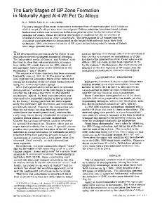
1 Introduction We have developed a sensor network that uses radio to communicate data and ultrasonic measurements to range between nodes, called the Parrot (see Fig. 1). The Parrot nodes enable a low-cost means of omni-directional ranging, suitable for localization in environments where standard localization systems such as GPS are not available or provide poor accuracy. The Parrot offers a decentralized and ad-hoc network structure that facilitates range-based localization of every node within the network. The system is indifferent to static and mobile nodes, thus, enabling a truly versatile and ad-hoc network. Our goal in developing the Parrot device was to allow user devices connected to any node within the network to obtain the necessary information about the network structure and localize the node’s position within the network. We present in this paper the various features and characteristics of the Parrot device. In addition we will demonstrate the reliability of the system in a network localization task and present its accuracy and robustness.
Figure 1: 6 identical sensor beacons shown. Each beacon consists of four pairs of ultrasonic transmitters and receivers arranged in a configuration such that signals can arrive from any direction. Range measurement between any pair of beacons is made available to the other beacons over a radio link. The bottom interface board measures 5" × 2.5", the top sensor board measures 3" × 3" and the sensor board is mounted 5" above the interface board.
2 Related Work Most sensor networks designed to aid localization systems measure relative bearing, range or in some cases both range and bearing between nodes within the environment. Possible approaches for bearing based network localization have been demonstrated recently ([1], [2], [3]). Marinakis and Dudek ([1]) present a technique to infer the topol1
ogy and connectivity information of a network of cameras based on Markov models of observed motion in the environment. An alternate MDS (Multidimensional Scaling) based approach for implicit estimation of the geometric locations of the camera sensors is described by Agathangelou et. al., [2]. More recently, Lee and Aghajan ([3]) present methods for estimating the node positions based purely on relative bearing measurements between image sensors. In addition, they emphasize the use of a mobile agent (with or without a known position estimate) to improve the localization of the entire network based on coupled observations of the mobile agent by several nodes in the network. While bearing based localization schemes have received more attention recently, other researchers have used range to localize the network. One commonly adopted approach, utilizes signal strength from a known transmitter to produce a “pseudorange” that is then used for triangulation. For instance, the Cricket System (a decentralized location-support system), [4] and [5], uses fixed ultrasound emitters and embedded receivers in the target object to localize the target. In addition, the Cricket system utilizes radio frequency (RF) signals are used to synchronize time measurements and to reject multipath readings. Alternately, Bahl and Padmanabhan present, the RADAR system [6], that uses the more commonly available 802.11b wireless networks for localization of network devices. This system uses the signal strength of each packet to localize a laptop. RADAR uses nearest neighbor heuristics to achieve localization accuracy of about 3 meters. Another system, the SpotOn system [7], provides an ad-hoc localization solution that localizes wireless devices relative to one another based on range estimated from radio signal attenuation. Other methods choose to train on patterns of signal strength to localize. For example, Ladd et. al. propose a Bayesian formulation to localize based on signal strength patterns from fixed receivers [8]. In this paper, we report the design and implementation of a range-only sensor network, which computes range using a combination of both RF and Ultrasonic signals, to aid robot localization tasks. The remainder of the paper is organized as follows. Section 3 describes the design and protocol of the Parrot sensor. Section 4 explores in detail that various operational modes available within the sensor. Experimental results demonstrating the noise characteristics, measurement update rates and localization performance are presented Section 5. Some concluding remarks are included in Section 6
3
System Architecture
Parrot nodes consist of a microcontroller (16-bit, 8MHz), a radio transceiver (outdoor communication range 1500 ft. and data rate 19.2Kbps) and four pairs of ultrasonic sensors (working freq. 40KHz). Each of these ultrasonic transducers has a limited directionality within which it can send/receive signals. Fig. 2 shows the plot of the signal strength compared to the angle of incidence to the sensor. By placing the four sensor pairs around the node at 90◦ intervals, we can achieve a full 360◦ field-of-view. Fig. 3 diagrams the various components of the Parrot nodes. As can be observed the ultrasonic sensors are placed on an extension board mounted on top of a stalk attached to the primary processing board. 2
Figure 2: A plot of the strength of the signal vs. the angle of incidence of the signal to the ultrasonic transducers. Figure borrowed from Data Sheet [9].
Figure 3: A diagram of the various components on the Parrot nodes.
3.1 Functionality and Control Scheme The primary function of the Parrot is measuring the distances between each other. This is accomplished through the use of both the radio and ultrasonic sensors equipped on the sensor. Each node within the network in turn sends out a radio signal followed by an ultrasonic pulse train (see Fig. 4). Other Parrots that receive both signals convert 3
the time difference between receiving the radio signal and the ultrasonic signal to a distance measurement by multiplying with the speed of sound. Distance = ((tR − tU S ) − 0.000815) ∗ VU S
(1)
where, tR is the time of arrival of the radio signal, tU S is the time of arrival of the ultrasonic signal and VU S is the speed of the ultrasonic signal through the environment.
RF
Figure 4: Sender sends out RF data followed by ultrasonic signals (a 40KHz pulse train). Receiver measures the time gap between the receipt of RF data at t0 and ultrasonic signals at t2 . Each node within the network takes turn transmitting its radio and ultrasonic pulses. The transmission order is controlled through the use of the supermedia access control scheme. This scheme initially assigns a random node as the starter and then forms a queue of all other active nodes within the environment (in range of its radio transceiver). This queue contains the transmission order and the node listed on top of the queue is allowed a limited amount of time to transmit its radio and ultrasonic pulses. Upon transmitting the necessary signals, the node updates the queue with any newly activated nodes and moves itself to the back of the queue. This newly modified queue is then transmitted to the other nodes to ensure proper syncing between all the nodes. If a given node fails to transmit its signals within a set timeout (determined by the maximum range of the ultrasonic transmitters), the next node on the queue begins its transmission. Upon failure/deactivation, nodes are removed from the queue when the remaining nodes fail to see any signs of activity, thereby improving overall network performance. The Parrots automatically formulate an ad hoc multi-hop wireless network to share the range information. They employ a distributed architecture in which every Parrot is able to acquire all the distance measurements from all the Parrots in the network, eliminating the requirement of a central node for the coordination and information exchange/collection. Sharing this information can at times become bandwidth consuming and can then negatively affect the performance of the system. In order to avoid such 4
difficulties, the Parrot nodes are equipped with four different operational modes that specify exactly which measurement information is exchanged and shared within the network. Further details of the different operational modes is described in Section 4. Compared with similar ultrasonic ranging nodes such as the Cricket, [5], the Parrot achieves a longer ranging distance of up to 15 meters with an accuracy of 2cm. It is also more effective in detecting ultrasonic signals by using four pairs of ultrasonic sensors, making it able to detect ultrasonic signals from any direction and reducing the number of nodes required by similar systems, which in turn leads to an improved update rate of the distance measurements improving the efficiency of tracking a moving object. Furthermore, since each of the four ultrasonic transmitter/receiver pair is directional, we can then estimate the direction of the signal (to approximately 90 degrees). This reduces the ambiguity inherent to omni-directional range-only sensors, thus improving the accuracy of standard localization and mapping algorithms. Our system, through the use of an unconstrained nonlinear optimization or an Extended Kalman Filter (EKF), is able to achieve accurate localization of the network. These results demonstrate the use of the Parrot nodes for target tracking and other localization tasks. Not unlike many similar systems, the Parrots do generate some noisy and outlier measurements. These measures, however, are easily handled by simple filtering schemes (i.e. χ2 filter) and our localization algorithms showed little/no loss in accuracy due to these measurements.
4 Operational Modes In order for a sensor network to be universal in its use, it needs easily scale to much larger network sizes without any change in system performance. The Parrot nodes facilitate scalability through the use of four different operational modes. These modes control information exchange within the network, thereby optimizing the amount of strain on the network bandwidth. In a truly large network, with dozens of nodes within the network, the optimizing network bandwidth is crucial and switching the operational modes of the parrots ensures that the Parrots do not transmit unnecessary and duplicate information across the network. The four modes function as follows: • Static Flooding: In this mode, every Parrot sends out ultrasonic signals to estimate the distances between itself and its neighbors. When a Parrot receives a distance estimation, it forwards the estimation to the serial port, and then propagates the estimation in which it is a receiver to the whole network. • Static Local Forwarding: In this mode, every Parrot sends out ultrasonic signals to estimate the distances between itself and its neighbors. When a Parrot receives a distance estimation, it forwards the estimation to the serial port, but won’t propagate the estimation to the whole network. Therefore the host is responsible for propagating the distance estimations to the whole network. • Dynamic Flooding: In this mode, the Parrot first figures out whether it is moving or not. Only the moving Parrots send out ultrasonic signals to estimate the distances between itself and its neighbors. When a Parrot receives a distance 5
estimation, it forwards the estimation to the serial port, and then propagates the estimation in which it is a receiver to the whole network. • Dynamic Local Forwarding: In this mode, the Parrot once again determines if it is moving or not. Only the moving Parrots send out ultrasonic signals to estimate the distances between themselves and their neighbors. When a Parrot receives a distance estimation, it forwards the estimation to the serial port, but won’t propagate the estimation to the whole network. Therefore the host is responsible for propagating the distance estimations to the whole network. In summary, every Parrot gets full network link information (measurements between all nodes in the network) when the network is in the flooding mode. When the system is in Dynamic mode, the Parrots first determine if they are moving by observing its estimated position over several time steps. By applying a threshold on its position estimate, the Parrot can roughly determine when it is in motion. However, in order for the Parrot to effectively detect if it is moving or not, it needs to be able to receive ultrasonic signals from at least three neighbors. Finally, when the network is in the forwarding mode, every Parrot gets partial link information, only measurements that the node itself received is known to that node, thus no measurement information is transmitted across the network. Suppose we have a 3-node Parrot network where node A is moving and the other two nodes (B and C) are static. The full network link distance estimation should consist of 6 sender to receiver pairs, A → B, A → C, B → A, B → C, C → A and C → B (where A → B represents the measurement sent from node A to B). The link information available in node B for the different operational modes are: • Static Flooding: In this mode, it gets distance estimations A → B, A → C, B → A, B → C, C → A and C → B. • Static Local Forwarding: In this mode, it gets distance estimations A → B, C → B. • Dynamic Flooding: In this mode, most of the time it gets distance estimations A → B, A → C, and in every 5 seconds, it gets distance estimations B → A, B → C, C → A and C → B. • Dynamic Local Forwarding: In this mode, most of the time it gets distance estimations A → B, and in every 5 seconds, it also gets distance estimation C → B. (if we monitor the network from node 1, then most of the time we won’t get any distance estimations. But in every 5 seconds we get distance estimations B → A and C → A). These four different operational modes, allow easy control over the information exchange and network stress. In small network sizes static flooding should be desired to provide each node with the most information, thus improving any localization algorithm. However, in large networks, switching to dynamic local forwarding might still provide a lot of measurements to each node and minimizing the strain on the network bandwidth while still achieving the desired localization accuracy. 6
5 Experiments We conducted several experiments to investigate the performance of the Parrot. The first experiment examined the noise characteristics of the Parrot nodes, revealing centimeter level accuracy. The second experiment was aimed to understand and compare the real world update rates with the ideal/theoretical rates for the various operational modes. The next experiments investigated the robustness of the system in localization tasks and examined the effectiveness of network localization in the presence of mobile nodes. Here we present experimental results for localizing the entire network using an unconstrained nonlinear optimization approach and using an EKF while incorporating the odometry from a mobile robot equipped with a Parrot node.
5.1 Noise Characteristics In our system, there are mainly two kinds of noises that affect the performance of the range estimation. One is the multi-path effects caused by the reflections of the ultrasonic pulses, yielding false results when they are captured by an ultrasonic transducer. To reduce the multi-path effects and also achieve 360 degree ranging capability, our ranging sensor uses four pairs of ultrasonic transducers facing four directions. The first ultrasonic transducer that captures a valid ultrasonic signal will inform the sensor to ignore the ultrasonic signals captured by any of the other three ultrasonic transducers, which are probably caused by the multi-path effects. Another kind of noise comes from the beacon wrongly correlating the RF data from one sender with the ultrasonic pulses from other sources: ultrasonic pulses sent out by another sensor, environmental noise, etc. Our experiments have shown that our beacons significantly reduce these noises, and accurately and reliably estimate range between each other. From the four experiments, we collected 20,014 inter-beacon range estimations by the beacons. Out of these estimations, we observed only 6 error estimations. To evaluate the precision of the system, we analyze the ranging performance between two beacons, and compare it with the range measurement using a tape measure. The result is illustrated in Fig. 5. This shows that the sensors accurately estimate the distance between the two beacons, and the difference between the average range estimation and the manually surveyed range measurement is 0.04 m (under ideal circumstances, where there are no multi-path effects on the sensors, the range error is approximately 0.02 m). Let us now examine the noise characteristics of the range measurements as a function of the true distance between the pair of beacons. Fig. 6 shows the mean and 3 sigma bounds of the measurements collected at the various ranges between a single pair of nodes. Here, a single node was moved in a two node network and range measurements were collected at 1 m intervals. A total of 1847 measurements were collected from 15 distinct surveyed locations with an average range error of less than 0.0185 m at each location. It can observed that most of the beacons can accurately and reliably estimate ranges between each other with a standard deviation of less than 0.04 m. Further experimentation demonstrate that range measurements between 21 pairs of beacons, with measurements ranging from 2 m to 10 m, mostly had errors less than 7
400
samples
350 300 250 200 150 100 50 0 6.64
6.66
6.68
6.7
6.72
6.74
6.76
6.78
6.8 6.82 range(m)
Figure 5: Histograms of a typical set of range measurements between two sensor beacons. The surveyed range measurement between the two beacons, measured using tape measure, is 6.65 m. The observed shift in the histogram is due to multi-path within the environment and imprecision in manual surveying. This level of accuracy is constant across ranges from 2 m to 15 m.
0.05 m. In this scenarios, we observed that one of the beacon pairs had a standard deviation of 0.4 m. Closer examination revealed that out of 341 range measurements between these two beacons, 335 of them were close to the true range of 7.75 m, and 6 of them are close to 5.15 m resulting in the higher standard deviation for this measurement pair. However, in most applications, such gross errors can be easily filtered out.
0.14
Avg. Range Error (Meas − True) 3−sigma bounds
Range Error [measured − true] (m)
0.12 0.1 0.08 0.06 0.04 0.02 0 −0.02 −0.04 −0.06 2
4
6
8 10 True Range (m)
12
14
Figure 6: Range error and 3-sigma bounds for range measurements between a pair of nodes as one node is moved at 1 m intervals. 1847 measurements collected from 15 distinct surveyed locations with range errors less than 0.0185 m and standard deviation less than 0.04 m.
8
5.2 Measurement Update Rates In the ideal scenario where every Parrot can receive the ultrasonic signals from all its neighbors, and none of the communication signals are lost, the measurement update rates of an N -Node Parrot network with M moving nodes in the four Operational modes are listed in Table 1 and Table 2. Estimations received from the serial port (per second) Static Flooding Static Local Forwarding Dynamic Flooding Dynamic Local Forwarding
N ∗(N −1) (α+β∗N +(β+γ∗N )∗N ) N −1 (α+γ∗N +β∗N ) M ∗(N −1) (α+γ∗N +(β+γ∗M )∗M +γ∗(N −M )∗M ) M (α+γ∗N +β∗M )
Table 1: Number of independent measurements received through the serial port for various operational modes. The parameters used in the table are α = 0.03, β = 0.052 and γ = 0.012, tuned based on environmental and system relative constants (i.e. room temperature, max. wait time between measurements, etc). Update rates of a full network link (Hz) Static Flooding Static Local Forwarding Dynamic Flooding Dynamic Local Forwarding
1 (α+γ∗N +(β+γ∗N )∗N ) 1 (α+γ∗N +β∗N ) 1 (α+γ∗N +(β+γ∗M )∗M +γ∗(N −M )∗M ) 1 (α+γ∗N +β∗M )
Table 2: Update rate to achieve full network link update. Here a full network link update is considered to be the total measurements achievable for any given operational mode as described in section 4. The parameters used in the table are α = 0.03, β = 0.052 and γ = 0.012, calibrated based on environmental and system relative constants (i.e. room temperature, max. wait time between measurements, etc). In the real world, the rates are less than the rates in the ideal condition due to the factors mentioned above and also due to the Parrots’ need to send out keep-alive signals when they are in the dynamic mode. For your reference, a 6-node Parrot network is used in this experiment with one moving node as the test bench. Using this setup, hour-long experiments were conducted for each operational mode and the results are compared with the ideal/theoretical update rates in Table 3. As can be expected, the ideal update rates are larger than the real world cases. However, it can be seen that the various operational modes help provide a wide array of measurement rates. This allows the user to choose the appropriate balance between the update rate and information exchange/availability between Parrot nodes.
5.3 Network Localization: Unconstrained Nonlinear Optimization Nonlinear optimization algorithms help provide reliable localization results when a fully connected network is available. In practice, networks rarely have a sufficient 9
Static Flooding Static Local Forwarding Dynamic Flooding Dynamic Local Forwarding
Full Network Link Update (Hz) Ideal Case Real World 1.2 1.0 2.4 2.3 4.4 3.1 6.4 5.2
Individual Meas. (Hz) Ideal Case Real World 35 28 12 11 22 20 6.5 6.3
Table 3: Expected (Ideal) and Observed Real world measurement update rates. number of neighbors to uniquely determine topology based on inter-node range measurements. Our approach attempts to minimize the errors in measurements observed between node pairs and arrives at an estimate of all inter-node ranges. These ranges are then used to solve an optimization problem that produces an estimate of each node with the network given using a single node as a reference node. This approach is demonstrated to produce reliable and locally accurate maps that correspond with the true locations of the nodes. It should also be noted here that in the general case where only range between nodes in a network is known the solution will contain both rotational and flip ambiguities (even in a fully connected network graph). This is due to the nature of range measurements and the lack of any constraints on the locations of the nodes. These ambiguities are resolved if and only if a few reference nodes are provided. The results obtained from this network localization approach is shown in Fig. 7.
5.4 Mobile Robot Experiment: EKF SLAM Our next experimental setup consisted of a sensor network composed of several Parrot nodes deployed arbitrarily in an environment along with a mobile robot platform (a standard Pioneer 1 platform developed by ActivMedia) manually controlled using a joystick and equipped with a single Parrot node (See Fig. 8). The robot was driven around manually, by joystick control, within a large indoor area with partial clutter. There was no ground truth available for the exact path taken by the robot, however, the robot’s intended path was surveyed. The true robot path differs somewhat from the intended path, however, it is close enough for the purposes of judging the validity of the localization and SLAM algorithm. In addition to the beacon that was placed on the robot, several other beacons were placed around the environment. The locations of these beacons were accurately surveyed to allow proper evaluation of the accuracy of our localization and mapping results. Utilizing the setup described above, we then used an Extended Kalman Filter (EKF), [10], to estimate both the position of the mobile robot and the locations of the other static Parrot sensors in the environment. Since no position information about the Parrots was provided to the EKF a priori, the estimator initially makes use of the odometry from the mobile robot to estimate the positions of the other Parrots. Each of the other Parrots’ position is estimated using a probability grid based approach (Olson et. al. [11]), which estimates each Parrot’s position based on an accumulated set of range measurements. Upon properly estimating the position of several Parrots, the range 10
Figure 7: Localization results of a 8-node network, the numbers inside the circles represent node IDs and their estimated positions; green lines show the estimated distance between pairs of nodes. (Left) The true surveyed solution. (Right) Output from unconstrained nonlinear optimization on measurements from network alone. This approach produces ambiguities (flip and rotational) and unstable solutions due to noise and partially connected networks. As can be observed this map although incorrect in appearance is indeed correct since it is simply presenting the solution with a flip (along the x-axis) and a small rotation, which is the best that can be achieved without any known fixed reference nodes. measurements from the tracked Parrots was then used to further improve the localization estimates of both the Parrot on the mobile robot and the other non-tracked Parrots. This approach provides reliable and accurate maps that other autonomous agents can use to localize themselves within the network. The localization and mapping results of the robot and Parrot network are presented in Fig. 9. A simple affine transform (AT) is performed on the final beacon locations estimates in order to re-align the locally accurate solution into a global coordinate frame. From the SLAM output it can be seen that it is indeed possible to extract an accurate estimate of the network topology.
6 Conclusion In this paper we presented a localization support system for indoor applications. We presented the design and implementation of the Parrot nodes that provide an ad-hoc homogeneous sensor network solution. This decentralized and low-cost solution utilizes RF and ultrasound signals to measure range between individual nodes within the network. Our system enables low network bandwidth overhead through the use of its 11
Figure 8: Robot used for our experiments shown along with a range sensing beacon mounted on top. The robot has wheel encoders that measure distance traveled and estimate heading. Neither estimate is good but the heading estimate is particularly poor. Tranformed Path from Kalman Filter SLAM GT Affine Trans. KF true beacon positions AT final beacon est.
x position (m)
4 2 0 −2 −4
0
2
4
6
8 10 12 y position (m)
14
16
18
20
Figure 9: EKF SLAM results along with intended ground truth path that the robot traveled. The location of the beacons is completely unknown at the start of SLAM. The path and beacon estimates shown include an affine transform that re-aligned the local solution acquired from the EKF into a global coordinate frame. four different operational modes that allow the user to vary the load on the network based on the application requirements. The Parrot device is able to share range measurement information within the network to facilitate and improve the accuracy of the localization nodes. By utilizing a decentralized control scheme the system is able to easily coordinate information exchange and measurement cycles, thus reducing signal interference and overlap. We have demonstrated the effectiveness and robustness of our system in localization tasks with the presence of both static and dynamic nodes. Furthermore, the results we have observed showed promise that our system could possibly be a good sensor network solution to large-scale dynamic localization tasks. Acknowledgements This material is based upon work supported by the National Science Foundation under Grant No. IIS-0426945.
12
References [1] D. Marinakis and G. Dudek, “Topology inference for a vision-based sensor network,” in The 2nd Canadian Conference on Computer and Robot Vision, 2005. [2] D. Agathangelou, B. Lo, J. Wang, and G. Yang, “Selfconfiguring video-sensor networks,” Proceedings of the 3rd International Conference on Pervasive Computing, 2005. [3] H. Lee and H. Aghajan, “Vision-enabled node localization in wireless sensor networks,” in COGnitive systems with Interactive Sensors (COGIS), 2006. [4] A. C. N. Priyantha and H. Balakrishman, “The cricket location support system,” in In Proc. of the 6th Annual ACM/IEEE International Conference on Mobile Computing and Networking (MOBICOM 2000), Boston, MA, August 2000. [5] A. Smith, H. Balakrishnan, M. Goraczko, and N. B. Priyantha, “Tracking Moving Devices with the Cricket Location System,” in 2nd International Conference on Mobile Systems, Applications and Services (Mobisys 2004), Boston, MA, June 2004. [6] P. Bahl and V. Padmanabhan, “Radar: An in-building rf-based user location and tracking system,” in In Proc. of the IEEE Infocom 2000, Tel Aviv, Israel, 2000. [7] R. W. J. Hightower and G. Borriello, “Spoton: An indoor 3d location sensing technology based on rf signal strength,” Tech. Rep. [8] A. Ladd, K. Bekris, G. Marceau, A. Rudys, D. Wallach, and L. Kavraki, “Robotics-based location sensing for wireless ethernet,” in Eighth ACM MobiCom, Atlanta, GA, September 2002. [9] Ultrasonic Transducers, Kobitone Audio Company, 2006, data sheet from Mouser Electronics. [10] J. Djugash, S. Singh, and P. Corke, “Further results with localization and mapping using range from radio,” in Proceedings, Fifth International Conference on Field and Service Robotics, Pt. Douglas, Australia. July 2005. [11] E. Olson, J. Leonard, and S. Teller, “Robust range-only beacon localization,” in Proceedings of Autonomous Underwater Vehicles, 2004, 2004.
13