ParSPIKE - A Parallel DSP-Accelerator for Dynamic Simulation of Large Spiking Neural Networks Carsten Wolff, Georg Hartmann, Ulrich Rückert Universität Paderborn, FB14 Elektrotechnik, Pohlweg 47-49, 33098 Paderborn Email:
[email protected]
Abstract The fast simulation of large networks of spiking neurons is a major task for the examination of biology inspired vision systems. Networks of this type are labelling features by synchronization of spikes and there is strong demand to simulate those effects in a real world environment. Because of the quite complex calculations for one model neuron the simulation of thousands or millions of these neurons is not efficient on existing hardware platforms. In order to simulate closer to the real time requirement, it is necessary to implement a dedicated hardware. Our aim is a hardware system mainly consisting of standard components which is as flexible as possible concerning the model neuron but as specialized as necessary to meet our performance requirements. Thus we decided to implement a parallel system with Digital Signal Processors (DSP) offering a large on-chip-memory. One main task of this work is the optimization of the simulation algorithm for the neurons distributed to the DSP which means the sequential part of simulation. This optimization benefits from the fact that there is only a very low percentage of simultaneously active neurons in vision networks. For communication between the nodes only spikes are distributed via a spike switching network. Processing of the network topology is realized by two different concepts. One idea is to compute the synapses autonomously on the processing node by representing a regular connection scheme with one connection mask for many neurons. Additional connections requiring adaptability and irregular connection schemes are stored in a shared memory. To avoid a bottleneck a synapse caching is used within each processing node. This paper describes the architecture of a DSP accelerator and shows the advantages with simulation results from a typical large vision network.
1. Introduction Efficient simulation of large pulse-coded neural networks (PCNN) is an important aim for further research on biology-inspired vision systems and brain research. Inves-
tigations have shown the advantages of spiking neurons [7][8] and special mechanisms like spike synchronization have been found in biological brains [2][3][6]. In order to evaluate the experimental results and the theoretical models and in order to build applicable vision systems it is necessary to simulate close to the conditions of biological systems. On the other hand the existing simulation techniques for large conventional neural networks are not adaptable for pulse-coded neural networks and simulation of pulse-coded networks is not efficient on existing hardware platforms [12][14][17] with exception of the Spike128k-architecture [4][9]. Because increasing simulation power is required we propose an enhanced Spike128k-architecture. The aim is to simulate networks with much more neurons and connections, to simulate them faster, to have more flexibility for modifications of the model neuron and to get an easier to handle system with a higher degree of integration.
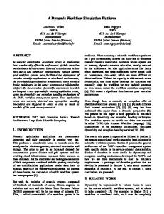
2. The Model Neuron Although the accelerator system described in this contribution is able to simulate different pulse-coded model neurons it is specialized to the simulation of Eckhorn Neurons [3]. These model neurons are modified French and Stein neurons [5] supporting especially the synchronization mechanisms with a modulatory dendritic linking tree. As the Spike128k system and several simulations on other hardware systems [12][13] also use Eckhorn neurons, simulations for our system are also based on this neuron for comparability. The Eckhorn model neuron uses a group of identically structured dendritic trees as an input (Fig. 2.1). The membrane potential of the neuron is driven by the postsynaptic potentials of these trees. Although a dendritic tree may have many synaptic weights there is only one common leaky integrator with one common time constant for all synapses of a tree. To reduce this restriction two trees (EP1 and EP2) with different time constants are provided for excitatory inputs.
... ...
S
LP
1
LP
t
S
EP1
Inhibitory feedinginputs
S
...
S
...
t
t
EP2
IP
DT
x
DToff
D DT
EP1
S
...
S DT
Excitatory feedinginputs
...
t
S 1+LP
...
Excitatory feedinginputs
t
...
Linkinginputs
Leakyintegrator
P S
EP2
+
MP
1
Output spike
IP
Figure 2.1: Eckhorn model neuron The postsynaptic potentials of both these trees are added. This potential is modulated by the postsynaptic potential of the so-called linking tree (LP). The resulting potential may be reduced by the postsynaptic potential of the inhibitory tree (IP) globally influencing the membrane potential (MP). The spike encoding circuitry, including the dynamic threshold (DT), is identical to that of French and Stein. With respect to motion detection and to the simulation of synchronization mechanisms an adjustable axonal delay and burst generation is added. Output spikes are transferred via weighted synapses to the input trees of other neurons. For realistic tests of our architecture we use a typical vision network developed by the Eckhorn group in Marburg [19]. This network provides contour segmentation on preprocessed input images and needs about 105 neurons and 4.106 connections. The network uses feature linking by synchronized spikes to represent coherent objects. It is part of the contour-form-system of a larger vision system and shows some characteristics which should be mentioned. The network is simulated for 2 sec of real-time corresponding 2000 timeslots. During this time the network input is stationary and in this segmentation task there is only sparse activity in most network layers. So only 14% of the neurons are active at one timeslot and only about 0.5% are emitting a spike. In tasks of this kind the group of active neurons changes quite slowly. We decided to use this network for the test of our architecture because it combines many typical parts of image processing with pulse-coded neurons.
3. Simulation of Spiking Neural Networks Most simulation systems for neural networks make use of vector processing by mapping neural networks in matrix representations [10]. These simulation algorithms are not efficient for pulse-coded neural networks because of the very complex calculations for one neuron and the sparse connectivity. Compared to conventional neural networks (McCulloch&Pitts neurons e.g.) matrix representations of pulse-coded neural networks would require additional sets of parameter vectors and matrices, and these matrices would mainly consist of zeros. An efficient simulation algorithm for pulse-coded neural networks has to make use of the low spike rates and the sparse connectivity by calculating only those neurons and connections that are involved in the momentary activity. These considerations lead to an individual calculation of neuron variables and connections and consequently to a sequential simulation of neurons. Sequential simulation of dynamic networks requires a timeslot simulation algorithm which guarantees that all parameters are updated before they are calculated again [4]. The aim of an accelerator system under these conditions is acceleration of the sequential simulation algorithm, reduction of the number of neurons and connections to be updated per timeslot, and distribution of the neurons onto as many parallel units as possible. Furthermore, we will show that we can benefit from the low spike rates to solve the communication problem in this massively parallel architecture. As we can hold the updating of neuron parameters in local nodes, the main part of calculation requires no additional communication. In the following, first the architecture of a node for se-
quential calculation is shown and in a second step the parallel architecture of a system with several nodes is described.
3.1 Sequential Simulation The sequential simulation makes use of some concepts from the Spike128k architecture [4][9]. The neurons are represented by their actual state parameters which are postsynaptic potentials, dynamic threshold and the parameters describing the neurons behavior. These parameters are stored in several neuron state memories with a common address for each neuron. For reading the parameter set of one neuron all these memories are accessed with this common neuron address. The simulation timeslot is divided into a decay phase and a stimulation phase. In the decay phase of a timeslot the neuron parameters are fetched, the membrane potential is calculated and compared with the dynamic threshold. If the neuron is supraliminal the spike encoder is activated and stores the neurons address onto a spike list mentioned below. The potentials and the threshold of the neuron are decayed due to the leaky integrators time constant and written back to the neuron state memory. In the stimulation phase of the timeslot the spike list is read to address the postsynaptic neurons. The state parameters (the postsynaptic potentials) of these neurons are modified according to the synaptic weights of the corresponding connections. neuron memory EP1 EP2 LP IP DT network topology wij
model neuron
j
i
spike list
Figure 3.1: Simulation cycle This simulation algorithm implements the spatio temporal integration of spikes with leaky integrators and the spike generation with a dynamic threshold. As previously mentioned, all addresses of neurons spiking in the corresponding timeslot are collected in the spike
list. So we can achieve that only those postsynaptic neurons addressed via the spike list are updated and we avoid the calculation of all synaptic connections in every timeslot. The connections are stored in a sender oriented way. The neuron address of the spiking neuron (sender) addresses a so-called stimulation information block (SIB) which contains the neuron addresses and the synaptic weights of the postsynaptic neurons. To allow SIBs with variable length these blocks are indirectly addressed via a block start memory. This block start memory contains a pointer for every possible presynaptic neuron address and with this pointer the SIB with the postsynaptic neurons is accessed. list-oriented interconnection storage network topology wij
block-startmemory
topology memory
j
BSA
i
SIB
Figure 3.1: Sender oriented topology storage Due to the selective processing of presynaptic neurons for the mentioned segmentation network with its 4.106 connections only about 28000 connections (0.7%) are calculated in each timeslot. A second possibility to avoid unnecessary calculations is to use a decay list. In the decay phase most neurons are totally inactive and those neurons cannot emit a spike. These neurons are of no interest and there is no need to calculate or decay their parameters. So if the state parameters of a neuron are on their rest values the neuron can be excluded from further calculations until it is again stimulated. The exclusion can be achieved by collecting the remaining neurons in a decay list. This decay list is updated in both phases of a timeslot. In the decay phase addresses of neurons with non-zero potentials are put to the list, while in the stimulation phase addresses of those neurons are collected which receive spikes. A tag memory is used to avoid multiple entries. In the case of the segmentation network only 17500 neurons are calculated instead of the 120000 neurons in the network which means a speed-up of 6.85 for the decay phase. It should be mentioned that this high speedup is achieved due to the very stable group of involved neurons in this example which is about 14% of all the neurons. Networks or input stimuli with a faster changing group of active neurons may lead to a lower speed-up. Until now we have saved calculation time by only updating neurons addressed via the spike list and by only decaying potentials of those neurons, collected on the decay list.
An additional way of saving calculation time is based on the following considerations: In the previously described concept (mainly based on the Spike128k architecture [4][9]), potentials are decayed in every timeslot. However, if there is neither activation by incoming spikes nor emission of spikes, incremental potential calculations per timeslot can be replaced by a single calculation combining a set of timeslots. Hence, this calculation only takes place if the neuron is stimulated or if a spike has to be emitted. In vision networks e.g., the stimulus may move and the activity distribution may be locally shifted. So there may be neurons not longer receiving any input and those neurons only have to be decayed until they reach their rest values. On the other hand the number of neurons receiving spikes depends on the number of spikes in the previous timeslot. This means that the number of processed neurons only depends on the spike rate and the connectivity of the network. If a(t) is the number of active neurons in timeslot t, s(t) the number of spiking neurons and k the mean number of connections per neuron, we get for the number of calculated neurons c(t) : c(t ) = s(t ) + s(t – 1) ⋅ k + s(t ) ⋅ k
(1)
instead of c(t ) = a(t ) + s(t ) ⋅ k
(2)
for the use of a decay list algorithm. Because the spike rate does not depend on the number of timeslots (in a certain range) that are used to represent one second of real time the number of calculated neurons in (1) is highly decoupled from the resolution of timesteps. Neurons which are only decaying to their rest values can be stored in a list until they are resubmitted. The calculation of the exact resubmission time is quite complex due to the many leaky integrators with different time constants. That is the reason why we use an iterative approach. potential values
e.g. 20 timeslots
dynamic threshold
rest values
membrane potential timeslots T1 T2 T3 resubmission times
Figure 3.2: Calculation of resubmission time
We only calculate a lower limit of the resubmission time assuming that the membrane potential remains unchanged until T1 in Fig. 3.2. After this time the neuron is resubmitted and the new membrane potential is calculated by decaying the postsynaptic potential according to the past time. Then this process is repeated. If a neuron is stimulated during the resubmission time it obviously must be calculated too. We realize this algorithm by using two time stamps for each neuron stored in the list. One stamp stores the timeslot for resubmission and one stamp stores the timeslot when the neuron was stored. For the processing of this time we only need two logarithmic calculations. Due to our simulation results we use 4 bit time stamps. A time stamp of zero represents an actually calculated neuron, time stamps of 15 represent totally inactive neurons. Longer resubmission stamps do not lead to longer real sleeping times for the neurons because most neurons are stimulated during their resubmission time. This effect is the reason for the quite low speed-up of 1.2 compared to the decay list algorithm that we get with simulations of the previously mentioned segmentation network. Other applications like motion detection with a changing group of involved neurons lead to a higher speed-up because the decay list algorithm has a lower speed-up for such an application. The total speed-up for the decay phase is 8 compared to the calculation of each neuron which means that 15000 neurons are calculated instead of 120000 neurons in the network.
3.2 Parallel Spike Processing As the spike rate of a pulse-coded neural network increases with the number of neurons a purely sequential simulation concept is not able to satisfy the performance requirements of larger networks. The distribution of work to several identical processing units has been a proper way for many applications. So it seems also likely to find a parallel procedure for simulation of pulse-coded neural networks. As we have seen the main processing amount for PCNNs is the calculation of the individual neurons and so we distribute the neurons to a set of processing nodes. If we are able to put all the neuron parameters of those neuron groups into the dedicated memory of the corresponding node we only have to transfer the spike list out of the node and to distribute it to the other nodes. The whole communication is based on neuron addresses and we can benefit from the low spike rates. Our aim is the development of a compact, easy to handle system and so we want to implement the processing nodes by DSPs without external dedicated memory. The chosen Analog Devices DSP has a relatively large but even limited on-chip memory and so we have the problem to store the SIBs of the network topology. There are two possibilities
to solve that problem: a large shared memory for all nodes or another more compact form of connection storage. The main part of information stored in the dedicated memory of the node are the neurons parameters like the postsynaptic potentials, the dynamic threshold and the parameters describing the neurons behavior. Additionally the resubmission list and the spike list are stored in the dedicated memory. Because of the memory limitations spike list and resubmission list are merged and the neuron parameters are stored in a compressed fixed point format. The remaining memory can be used for storing the network topology. Until now, e.g. in the Spike128k [4][9], we store an individual set of target addresses for each sender address in the SIB. In regular connection structures, however, as they occur in vision networks, target neurons may be addressed relatively by a set of address offsets to the corresponding sender address. We call this set of address offsets "connection mask" and we have to store this mask only once. This type of connection representation has been proposed in [16]. The mask can be stored in the same format as a SIB with one difference: the addresses of the postsynaptic target neurons are not absolute neuron addresses but address offsets. In the case of regular connection representation the block start addresses in the block start memory do not point to different SIBs for each neuron but to the same SIB for a total layer of neurons. In typical vision networks we have many layers with highly regular detector masks so we can simulate a large number of neurons by very few regular connection masks. In the dedicated node memory the block start memory for the local neurons and appropriate SIB-masks have to be stored. To allow input to the local part of the network from other neurons the SIBs for a limited number of external neurons (on other nodes) have to be stored on the node too. The number of those external neurons is one restriction of this approach. We decided to allow as much presynaptic external neurons as local ones. To compute the whole network the processing nodes have to communicate via address exchange. Even if we have low spike rates the communication via a shared bus would limit the number of possible nodes. A much better way is the implementation of a spike switching network. The nodes are connected to spike switches which are connected to other switches or to other nodes. The neuron addresses can be used for routing to target nodes. To support this routing mechanism, the neuron addresses are arranged in corresponding address blocks. These blocks are described by a start address and an end address stored in registers in the switch. This algorithm can be implemented in a hardware pipeline and these configurable hardware switches are used to build the switching network. There are
several possibilities to realize the switching network. The architecture for our accelerator is a tree with the host as a root and the processing nodes as leaves. An accelerator for the highly regular network topologies of the early vision stages only consists of the nodes and the address switching tree. Within a system which only uses regular connection masks there is no possibility for irregular connections or adaptability. To implement these features individual SIBs for each neuron are needed and this leads to memory requirements which cannot be granted by the dedicated memory of the nodes. A shared memory system for all nodes is necessary to offer the required memory amount in a efficient way. To provide this shared memory resource, the whole network topology is stored in the above described sender oriented way in a memory subsystem at the root of the address switching tree. All presynaptic neuron addresses are transmitted to a spike list at this memory subsystem. In the stimulation phase the postsynaptic spikes and the weights from the stored SIBs are transmitted to the nodes. As already mentioned, a large shared memory allows the storage of individual weights and so it also allows individual modification by learning. Based on a network topology with individual SIBs for each neuron the Hebb’ian-like learning algorithm of the Spike128k system [4][9] can also be implemented for a parallel accelerator system. For this learning rule a special adaptation for PCNNs should be mentioned: In a pulse-coded neural network the coincidence of spikes at the presynaptic and the postsynaptic neuron is accidental because the spike is only a coding of activity. To provide the information if a neuron is active we introduced the "ready for learning" RFL which is used in our learning rule. A neuron is RFL if the membrane potential exceeds a static learning threshold. A simple formulation of the learning rule is: If the postsynaptic neuron is RFL and the presynaptic neuron is spiking -> increment the synaptic strength If the postsynaptic neuron is RFL and the presynaptic neuron is not spiking -> decrement the synaptic strength To provide the RFL information at the shared memory system additionally to the spike list a address list of RFL neurons is transmitted via the address switching tree. The learning procedure is calculated in the decay phase and delayed by one timeslot. The learning algorithms should not be the topic of this contribution. They are described in [4][9] in more detail. As main advantage the shared memory system allows inclusion of learning and non regular connection schemes.
However a higher hardware expense, the more intensive communication, and the limited processing power due to a shared resource are the main problems. A solution avoiding a bottleneck is caching of synapses or SIBs at the nodes. Usually used caching algorithms like "last recently used" (LRU) or "most recently used" are not profitable for a spike processing system because those neurons which emitted a spike are refractory for a longer time period and the cache control algorithm would move the SIB out of the cache. But those eliminated SIBs are used with high probability in the further simulation steps because the neuron is still active and becomes supraliminal with higher probability than other neurons. The caching algorithm for a spike processing system has to hold the SIBs in the cache for a much longer period than typical cache algorithms. Especially, neurons with axonal delay or postsynaptic potentials which have not reached their rest values have to be stored in the cache. Those informations are available at the nodes because they store all the neuron state parameters. Our cache implementation needs a cache size of 64k synapses (for the segmentation net with 4 M synapses in total) and achieves a cache hit rate of 96%. With a special tag bit the memory subsystem at the root of the spike switching network gets the information, that for a presynaptic spike found in the cache no SIB has to be transferred to the node. By concentrating the main processing work on the nodes, by storing most of the required information in the dedicated memory and by using a special spike switching network for communication we can implement a compact accelerator system. Another essential problem of parallel processing systems which is not yet mentioned is the distribution of workload. For our accelerator the workload is balanced by suitable distribution of the neurons. This partitioning of the network is realized by a special compiler. Neural networks for our new accelerator system as well as for the existing Spike128k system [4][9] and for several other systems [13] are described with the network description language MNET which has been developed in Marburg at the Eckhorn group. For the parallel accelerator system a new MNET compiler is implemented which uses graph partitioning and layer based partitioning algorithms from the PARTY library [15]. This compiler also creates the regular connection masks and the switching information for the spike switches.
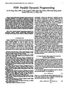
4. DSP-based Implementation Our proposed accelerator implementation is based on Analog Devices ADSP21060 with 512 kByte on-chip memory. The switching network and the memory control-
ling circuitry is designed for Xilinx XC4000 FPGAs. We are going to implement a prototype system for up to one million neurons and up to 30 million connections which will be scalable up to 4 million neurons. The accelerator is proposed as a VME-based system with a VME-Sparc as a host computer. It will contain one modified VME board for regular connections simulating up to 512k neurons, and two boards with a shared memory system simulating 256k neurons each. VME-Bus-System
TM
TM
SIB TM
TM
TM
TM
SIB TM
NRC-Unit
TM
NRC-Unit
(non regular connections/ (non regular connections/ 256k neurons) 256k neurons)
FORCE VME-Sparc
RC-Unit
(regular connections/ 512k neurons)
Sun SPARC
Figure 4.1: Accelerator system The main board area is covered with an array of DSP’s. The so-called SHARC-DSP consists of a floating point unit with 3 parallel calculation units, two independent 256 kByte dual-ported SRAMs, an IO-processor with up to six linkports and a multiprocessor interface. The dual-ported SRAM allows one-clock access to the neuron parameters. By using this dual-ported RAM, the register file of the core processor, and the instruction cache, a one-clock command execution is achieved. Furthermore the communication overhead for the neuron address exchange with other nodes is processed by the IO-processor. The SHARC-DSP is clocked with 40 MHz. The regular connection board (RC) consists of up to 32 SHARC processors, six FPGAs for the switching network and a VME interface. Groups including four DSPs and one FPGA interface are connected to one common bus via their multiprocessor interface. These FPGAs are connected to the next ones and those are connected to the VME bus. The FPGAs are clocked with 20 MHz. Both the DSPs and the FPGAs will run with 3.3 V. The FPGAs implement the so-called communication unit (CU), an unique switch design with different interfaces. The CU consists of an initialization data path for reading and writing the DSP memories and two spike switching data paths for the leave-to-root direction and the root-toleave direction. Those switching paths only transmit
matching neuron addresses. Other neuron addresses fetched from the bus are rejected. Init
leaves
DSP Interface
root
VME Interface
r/w address
select
decode
Work range
CU Interface 1
5. Conclusion
CU Interface 2
select range select
WMC Interface
select all Work AddressGenerator
Figure 4.3: The communication unit (CU) The accelerator boards for the non regular connection boards (NRC) consists of up to 16 processing nodes and implement the spike switching tree of the RC-board too. Furthermore the shared memory subsystem is realized on the NRC-board. It consists of three SDRAM modules, the weight memory controller (WMC) and the learning unit (LU). The spike switching tree of the NRC board only transmits presynaptic spikes from the leaves to the root which means from the nodes to the WMC. Node1
Node2
4 bit
4 bit
>> shiftregister
Node16
Linkports
4 bit
>> shiftregister
>> shiftregister
spikeaddress
BSA 16-bit count
BSA
BSA
16-bit count
WMC W memory addresses
16-bit count
BSS spikelistcontrol
spikelist
SDRAM-Readbuffer
W memory data
highly connected with the WMC design. Two spike lists are used alternatively so the LU can access the old spike list when a new spike list is written. For the forgetting process an inverse network topology is provided in one of the SDRAM (synchronous DRAM) modules.
SDRAM-Interface
Figure 4.4: Weight memory controller (WMC) The retransmission of the postsynaptic spikes makes use of the linkports of the DSPs. One linkport for each DSP is connected to the WMC and only the SIB parts for this special DSP are transmitted via the link. The decision which postsynaptic spike has to be transmitted via which link can be made easily by the neuron address of the postsynaptic neuron.The WMC has also access to the global spike list stored at the root of the spike switching tree and to the block start memory BSS. The design of the learning unit is
In this presentation an architecture has been shown which will allow the simulation of pulse-coded neural networks with millions of neurons. Furthermore, this architecture implies the advantage that the future improvements in circuit technology can be implemented easily and an upgrade path to even larger networks is given. The Spike128k architecture is improved with respect to many items and the implementation is less expensive than in the existing Spike128k system. With a parallel simulation architecture the capability is given to decouple the simulation speed from the number of neurons in a wide range. This parallel solution for the simulation of pulse-coded neural networks will lead to further expansions with respect to the amount of neurons and the network size to be simulated. The architecture and the algorithms have been tested with a typical application [19] to get comparable results. These simulations have been done with a PVM software simulator on a Sun workstation cluster and with an Analog Devices DSP evaluation kit. The software simulations allow a comparison with several hardware platforms. The network has been simulated on Sun Sparc and Ultra workstations and on a DEC Alpha system in Marburg. It has been simulated and demonstrated on the Spike128k system [9]. The network has about 120000 neurons and about 4 million connections with a mean activity of 14% and a mean spike rate of 0.5%. A network with similar characteristics (20% activity/0.5% spike rate) has been the base of simulations and estimations for other hardware platforms [12][18]. The given performance overview in table 5.1 is not a real measurement result or a benchmark but an attempt to get a classification of the proposed DSP accelerator. The values which are marked by (*) are estimated (partly from the simulation results with fewer neurons, partly from calculations), those marked by (B) are from [12][18], unmarked results are measured. It should be mentioned that the simulation times are measured (or estimated) for one timeslot which represents 1 ms of biological real time. This real-time requirement can only be achieved by proposed special processor architectures like MASPINN[18] or by an optimized parallel architecture like ParSPIKE.
UltraSparc2 200MHz
Number of Neurons
DEC Alpha 266MHz
CNAPS 50MHz/ 256PE
Pentium II 266 MHz
SPIKE128k 10MHz/1PE
NESPINN 50MHz/ 4PE
MASPINN 100MHz/ 4PE
ParSPIKE 40MHz/ 64PE
16k
11 ms *
18 ms *
10 ms B
1.5 ms B
1.5 ms
0.38ms *B
0.06 ms *B
< 1 ms *
128k
85 ms
140 ms
85 ms B
~1 s *B
9 ms
3 ms *B
0.39 ms *B
< 1 ms *
512k
-
-
427 ms B
-
11 ms (4PE)*
11.7 ms *B
1.56 ms *B
2.5 ms *
1M
-
-
-
-
11 ms (8PE)*
23.4 ms *B
3.1 ms *B
5 ms *
Table 5.1: Performance of the ParSPIKE architecture compared to other hardware platforms
6. Acknowledgment
[9]
This work has been partly supported by the Deutsche Forschungsgemeinschaft (German Research Council) DFG graduate college "Parallele Rechnernetzwerke in der Produktionstechnik" Me872/4-1.
[10]
7. References
[11]
[1]
[2]
[3]
[4]
[5]
[6]
[7]
[8]
J. Deppisch, K. Pawelzik, T. Geisel: "Uncovering the synchronization dynamics from correlated neural activity quantifies assembly formation." Biol. Cybern. 71, pp. 387399 (1994) R. Eckhorn, H. J. Reitböck, M. Arndt, P. Dicke: "Feature Linking via Stimulus - Evoked Oscillations: Experimental Results for Cat Visual Cortex and Functional Implications from a Network Model." Proc. IJCNN89, Vol. I, pp. 723730 (1989) R. Eckhorn, H. J. Reitböck, M. Arndt, D. Dicke: "Feature Linking via Synchronization among Distributed Assemblies: Simulations of Results from Cat Visual Cortex." Neural Computations 2, pp. 293-307 (1990) G. Frank, G. Hartmann: "An Artificial Neural Network Accelerator for Pulse-Coded Model Neurons." ICNN95, Perth, Australia, In: Proc. ICNN95, Vol. 4, pp. 2014-2018 (1995) A. S. French, R. B. Stein: "A Flexible Analog Using Integrated Circuits." IEEE Transactions on Bio-Medical Engineering, Vol. BME-17, No. 3, pp. 248-253 (1970) C. M. Gray, W. Singer: "Stimulus-specific neuronal oscillations in orientation columns of cat visual cortex." Proc. Natl. Acad. Sci. USA, 86, pp, 1698-1702 (1989) G. Hartmann, S. Drüe: "Self Organization of a Network Linking Features by Synchronization." In: Parallel Processing in Neural Systems and Computers, G. Hauske (ed.), pp. 361-364 (1990) G. Hartmann: "Motion Induced Transformations of Spatial Representations: Mapping 3D Information onto 2D." In: Neural Networks, Vol. 5, pp. 823-834 (1992)
[12]
[13]
[14]
[15]
[16]
[17]
[18]
[19]
G. Hartmann, G. Frank, M. Schäfer, C. Wolff: "SPIKE128K - An Accelerator for Dynamic Simulation of Large Pulse-Coded Networks." MicroNeuro 97, Dresden, pp. 130-139 (1997) J.N.H. Heemskerk : "Neurocomputer for Brain-Style Processing. Design, Implementation and Application." Ph.D. thesis at Leiden University, Rijksuniverditeit Leiden, Netherlands (1995) A. Jahnke, U. Roth, H. Klar: "A SIMD/Dataflow Architecture for a Neurocomputer for Spike-Processing Neural Networks (NESPINN)." MicroNeuro 96, Lausanne, Switzerland, pp. 232-237 (1996) A. Jahnke, T. Schoenauer, U. Roth, K. Mohraz, H. Klar: "Simulation of Spiking Neural Networks on Different Hardware Platforms." In: Artificial Neural NetworksICANN97. Springer Verlag, Berlin, pp.1187-1192 (1997) K. Mohraz, U. Schott, M. Pauly: "Parallel Simulation of Pulse-Coded Neural Networks." In: Proceedings of the IMACS World Congress '97, Berlin, Vol. 6, pp. 523-528 (1997) E. Nierbur, D. Brettle: "Efficient Simulation of Biological Neural Networks on Massively Parallel Supercomputers with Hypercube Architecture." Advances in Neural Information Processing Systems 6, pp 904-910 (1994) R. Preis, R. Diekmann: "PARTY - a software library for graph partitioning", In: B.H.V. Topping, editor, Advances in Computational Mechanics with Parallel and Distributed Processing, pp 63-71 (1997) U. Roth, F. Eckhardt, A. Jahnke, H. Klar: "Efficient OnLine Computation of Connectivity: Architecture of the Connection Unit of NESPINN." MicroNeuro 97, Dresden, pp. 31-38 (1997) U. Roth, A. Jahnke, H. Klar: "Hardware Requirements for Spike-Processing Neural Networks. IWANN 95, Malaga, Spain, pp. 720-727(1995) T. Schoenauer, N. Mehrtash, A. Jahnke, H. Klar: "MASPINN: Novel Concepts for a Neuro-Accelerator for Spiking Neural Networks" In: VIDYNN’98, Stockholm, (1998) L. Weitzel, K. Kopecz, C. Spengler, R. Eckhorn, H. J. Reitböck: "Contour Segmentation with Recurrent Neural Networks of Pulse-Coding Neurons." CAIP’97, Kiel (1997)