3.1.1 Definitions...................................................................................................48 ..... Definition of Terms and Symbols..............................................................................238.
Particle Swarm Optimization Methods for Pattern Recognition and Image Processing by Mahamed G. H. Omran
Submitted in partial fulfillment of the requirements for the degree Philosophiae Doctor in the Faculty of Engineering, Built Environment and Information Technology University of Pretoria Pretoria November 2004
Particle Swarm Optimization Methods for Pattern Recognition and Image Processing by Mahamed G. H. Omran
Abstract Pattern recognition has as its objective to classify objects into different categories and classes. It is a fundamental component of artificial intelligence and computer vision. This thesis investigates the application of an efficient optimization method, known as Particle Swarm Optimization (PSO), to the field of pattern recognition and image processing. First a clustering method that is based on PSO is proposed. The application of the proposed clustering algorithm to the problem of unsupervised classification and segmentation of images is investigated. A new automatic image generation tool tailored specifically for the verification and comparison of various unsupervised image classification algorithms is then developed. A dynamic clustering algorithm which automatically determines the "optimum" number of clusters and simultaneously clusters the data set with minimal user interference is then developed. Finally, PSO-based approaches are proposed to tackle the color image quantization and spectral unmixing problems. In all the proposed approaches, the influence of PSO parameters on the performance of the proposed algorithms is evaluated. Key terms: Clustering, Color Image Quantization, Dynamic Clustering, Image Processing, Image Segmentation, Optimization Methods, Particle Swarm Optimization, Pattern Recognition, Spectral Unmixing, Unsupervised Image Classification.
Thesis supervisor: Prof. A. P. Engelbrecht Thesis co-supervisor: Dr. Ayed Salman Department of Computer Engineering, Kuwait University, Kuwait
Department of Computer Science Degree: Philosophiae Doctor ii
“Obstacles are those frightening things you see when you take your eyes off your goal.” Henry Ford
“You will recognize your own path when you come upon it, because you will suddenly have all the energy and imagination you will ever need.” Jerry Gillies
iii
Acknowledgments
I address my sincere gratitude to God as whenever I faced any difficulty I used to pray to God to help me and He always was there protecting and saving me. Then, I would like to express my warm thanks to Professor Andries Engelbrecht, who spared no effort in supporting me with all care and patience. I enjoyed working with him, making every moment I spent in the research work as enjoyable as can be imagined. I would like also to thank my co-supervisor Dr. Ayed Salman from Kuwait University for his continuous guidance, encouragement and patience throughout the PhD journey. I will never forget the long hours we spent together discussing various ideas and methods. Last but not least, I would love to thank my family for their support and care, especially my mother Aysha and my father Ghassib. May God bless and protect them both hoping that God will help me to repay them part of what they really deserve. I also thank my two sisters Ala'a and Esra'a for their help in preparing this thesis.
iv
Contents Chapter 1 Introduction....................................................................................................................1 1.1 Motivation............................................................................................................1 1.2 Objectives ............................................................................................................2 1.3 Methodology ........................................................................................................3 1.4 Contributions........................................................................................................4 1.5 Thesis Outline ......................................................................................................5 Chapter 2 Optimization and Optimization Methods.......................................................................7 2.1 Optimization ........................................................................................................7 2.2 Traditional Optimization Algorithms ................................................................10 2.3 Stochastic Algorithms ........................................................................................11 2.4 Evolutionary Algorithms ...................................................................................12 2.5 Genetic Algorithms............................................................................................15 2.5.1 Solution Representation ..............................................................................16 2.5.2 Fitness Function ..........................................................................................16 2.5.3 Selection......................................................................................................17 2.5.4 Crossover ....................................................................................................19 2.5.5 Mutation......................................................................................................20 2.5.6 The Premature Convergence Problem ........................................................22 2.6 Particle Swarm Optimization.............................................................................23 2.6.1 The PSO Algorithm ....................................................................................23 2.6.2 The lbest Model ..........................................................................................26 2.6.3 PSO Neighborhood topologies ...................................................................28 2.6.4 The Binary PSO ..........................................................................................29 2.6.5 PSO vs. GA.................................................................................................31 2.6.6 PSO and Constrained Optimization ............................................................32 2.6.7 Drawbacks of PSO......................................................................................33 2.6.8 Improvements to PSO .................................................................................34 2.7 Ant Systems .......................................................................................................45 2.8 Conclusions........................................................................................................46 Chapter 3 Problem Definiton........................................................................................................47 3.1 The Clustering Problem .....................................................................................47 3.1.1 Definitions...................................................................................................48 3.1.2 Similarity Measures ....................................................................................49 3.1.3 Clustering Techniques ................................................................................51 3.1.4 Clustering Validation Techniques...............................................................64 3.1.5 Determining the Number of Clusters..........................................................69 3.1.6 Clustering using Self-Organizing Maps......................................................75
v
3.1.7 Clustering using Stochastic Algorithms......................................................78 3.1.8 Unsupervised Image Classification.............................................................82 3.2 Image Segmentation using Clustering ...............................................................83 3.2.1 Thresholding Techniques............................................................................84 3.2.2 Edge-based Techniques ..............................................................................84 3.2.3 Region growing Techniques .......................................................................85 3.2.4 Clustering Techniques ................................................................................85 3.3 Color Image Quantization..................................................................................89 3.3.1 Pre-clustering approaches ...........................................................................91 3.3.2 Post-clustering approaches..........................................................................94 3.4 Spectral Unmixing .............................................................................................97 3.4.1 Linear Pixel Unmixing (or Linear Mixture Modeling)...............................98 3.4.2 Selection of the End-Members..................................................................100 3.5 Conclusions......................................................................................................103 Chapter 4 A PSO-based Clustering Algorithm with Application to Unsupervised Image Classification..............................................................................................................104 4.1 PSO-Based Clustering Algorithm....................................................................104 4.1.1 Measure of Quality ...................................................................................104 4.1.2 PSO-Based Clustering Algorithm.............................................................105 4.1.3 A Fast Implementation..............................................................................107 4.2 Experimental Results .......................................................................................108 4.2.1 gbest PSO versus K-Means.......................................................................111 4.2.2 Improved Fitness Function .......................................................................114 4.2.3 gbest PSO versus GCPSO.........................................................................115 4.2.4 Influence of PSO Parameters ....................................................................116 4.2.5 gbest PSO versus state-of-the-art clustering algorithms ..........................122 4.2.6 Different Versions of PSO ........................................................................126 4.2.7 A Non-parametric Fitness Function..........................................................128 4.2.8 Multispectral Imagery Data ......................................................................129 4.2.9 PSO for Data Clustering ...........................................................................134 4.3 Conclusions......................................................................................................134 Chapter 5 SIGT: Synthetic Image Generation Tool for Clustering Algorithms.........................136 5.1 Need for Benchmarks ......................................................................................136 5.2 SIGT: Synthetic Image Generation Tool .........................................................138 5.2.1 Synthetic Image Generator .......................................................................139 5.2.2 Clustering Verification Unit .....................................................................141 5.3 Experimental Results .......................................................................................144 5.4 Conclusions......................................................................................................146
vi
Chapter 6 Dynamic Clustering using Particle Swarm Optimization with Application to Unsupervised Image Classification............................................................................153 6.1 The Dynamic Clustering using PSO (DCPSO) Algorithm..............................153 6.1.1 Validity Index ...........................................................................................158 6.1.2 Time Complexity ......................................................................................158 6.2 Experimental results.........................................................................................159 6.2.1 Synthetic images .......................................................................................162 6.2.2 Natural images ..........................................................................................163 6.2.3 Comparison with GA and RS ...................................................................166 6.2.4 Swarm Size ...............................................................................................167 6.2.5 The Termination Criteria ..........................................................................168 6.2.6 pini and Nc ..................................................................................................171 6.2.7 Comparison of gbest-, lbest- and lbest-to-gbest-PSO...............................173 6.2.8 Multispectral Imagery Data ......................................................................174 6.3 Conclusions......................................................................................................175 Chapter 7 Applications ...............................................................................................................177 7.1 A PSO-based Color Image Quantization Algorithm .......................................177 7.1.1 The PSO-based Color Image Quantization (PSO-CIQ) Algorithm..........178 7.1.2 Experimental Results ................................................................................181 7.2 A PSO-based End-Member Selection Method for Spectral Unmixing of Multispectral Satellite Images................................................................................192 7.2.1 The PSO-based End-Member Selection (PSO-EMS) Algorithm .............192 7.2.2 Experimental Results ................................................................................195 7.3 Conclusions......................................................................................................207 Chapter 8 Conclusion .................................................................................................................208 8.1 Summary ..........................................................................................................208 8.2 Future Research ...............................................................................................210 Bibliography ..............................................................................................................213 Appendix A Definition of Terms and Symbols..............................................................................238 Appendix B Derived Publications..................................................................................................239
vii
List of Figures Figure 2.1: Example of a global minimizer x ∗ as well as a local minimizer x B∗ .......10 Figure 2.2: General pseudo-code for EAs....................................................................13 Figure 2.3: General pseudo-code for PSO ...................................................................27 Figure 2.4. A diagrammatic representation of neighborhood topologies ....................29 Figure 3.1: General pseudo-code for SOM..................................................................76 Figure 3.2: Rectangular Lattice arrangement of neighborhoods .................................77 Figure 3.3: General simulated annealing based clustering algorithm..........................78 Figure 3.4: General pseudo-code for GA-based clustering algorithm.........................80 Figure 4.1: The PSO clustering algorithm .................................................................107 Figure 4.2: Data set consisting of synthetic, MRI and LANDSAT images...............110 Figure 4.3: PSO Performance on Synthetic Image ....................................................112 Figure 4.4: The Segmented Synthetic Images ...........................................................113 Figure 4.5: The Segmented MRI Images...................................................................113 Figure 4.6: The Segmented Lake Tahoe Images .......................................................113 Figure 4.7: Effect of swarm size on synthetic image.................................................118 Figure 4.8: Effect of swarm size on MRI image........................................................119 Figure 4.9: The Landsat MSS test images of Lake Tahoe.........................................132 Figure 4.10: The Thematic Maps for Lake Tahoe Image Set ....................................133 Figure 5.1: The synthetic image generator algorithm................................................140 Figure 5.2: The clustering verification algorithm ......................................................143 Figure 6.1: The DCPSO algorithm ............................................................................156 Figure 6.2: Natural Images ........................................................................................160 Figure 6.3: 6-Clusters thematic map obtained using DCPSO....................................175 Figure 7.1: The PSO-CIQ algorithm..........................................................................180 Figure 7.2: Quantization results for the Lenna image using PSO-CIQ ....................184 Figure 7.3: Quantization results for the peppers image using PSO-CIQ ..................185 Figure 7.4: Quantization results for the jet image using PSO-CIQ ..........................186 Figure 7.5: Quantization results for the mandrill image using PSO-CIQ.................187 Figure 7.6: The PSO-EMS algorithm ........................................................................195 Figure 7.7: AVHRR Image of UK, Size: 847x1009 , 5 bands, 10-bits per pixel .....199 Figure 7.8: Species concentration maps resulting from the application of ISOUNMIX to unmix the Lake Tahoe test image set ......................................................200 viii
Figure 7.9: Species concentration maps resulting from the application of PSO-EMS to unmix the Lake Tahoe test image set.....................................................................201 Figure 7.10: Species concentration maps resulting from the application of ISOUNMIX to unmix the UK test image set ...................................................................202 Figure 7.11: Species concentration maps resulting from the application of PSO-EMS to unmix the UK test image set..................................................................................203
ix
List of Tables Table 4.1: Comparison between K-means and PSO..................................................112 Table 4.2: 2-component versus 3-component fitness function ..................................115 Table 4.3: PSO versus GCPSO..................................................................................116 Table 4.4: Effect of inertia weight on the synthetic image ........................................120 Table 4.5: Effect of inertia weight on the MRI image ...............................................120 Table 4.6: Effect of acceleration coefficients on the synthetic image .......................121 Table 4.7: Effect of acceleration coefficients on the MRI image ..............................121 Table 4.8: Effect of sub-objective weight values on synthetic image .......................123 Table 4.9: Effect of sub-objective weight values on MRI image ..............................124 Table 4.10: Comparison between K-means, FCM, KHM, H2, GA and PSO for fitness function defined in equation (4.6)..............................................................................125 Table 4.11: Comparison of different PSO versions ...................................................127 Table 4.12: Comparison between K-means, FCM, KHM, H2, GA and PSO for fitness function defined in equation (4.7)..............................................................................130 Table 4.13: Comparison between different non-parametric fitness function ............131 Table 4.14: Comparison between K-means, gbest PSO and lbest-to-gbest PSO when applied to multispectral image set..............................................................................131 Table 5.1: Synthetic image details and classification accuracy.................................148 Table 5.2: Synthetic images, Histograms and Thematic Maps..................................149 Table 5.2 (continued). ................................................................................................150 Table 5.2 (continued). ................................................................................................151 Table 5.2 (continued). ................................................................................................152 Table 6.1: Additional synthetic images used along with the corresponding histograms ....................................................................................................................................161 Table 6.2: Experiments on synthetic images .............................................................163 Table 6.3: Experiments on natural images.................................................................164 Table 6.4: Samples of segmented images resulting from DCPSO using V ...............165 Table 6.4: Samples of segmented images resulting from DCPSO using V (continued) ....................................................................................................................................166 Table 6.5: Comparison of PSO-, GA- and RS- versions of the proposed approach..167 Table 6.6: Comparison of PSO- and GA- versions of the proposed approach using a swarm size s = 20.......................................................................................................168
x
Table 6.7: Effect of termination criterion TC1 on the DCPSO using a swarm size s = 20 and TC2= 2 ............................................................................................................170 Table 6.8: Effect of termination criterion TC2 on the DCPSO using a swarm size s = 20 and TC1= 50 ..........................................................................................................171 Table 6.9: Effect of pini on the DCPSO using a swarm size s = 20 ..........................172 Table 6.10: Effect of Nc on the DCPSO using a swarm size s = 20 .........................173 Table 6.11: Comparison of gbest-, lbest- and lbest-to-gbest- PSO versions of DCPSO using V (s = 20) ..........................................................................................................174 Table 7.1: Comparison between SOM, GCMA and PSO-CIQ .................................183 Table 7.2: Effect of Vmax on the performance of PSO-CIQ using Lenna image (16 colors) ........................................................................................................................188 Table 7.3: Effect of the swarm size on the performance of PSO-CIQ using Lenna image (16 colors) .......................................................................................................189 Table 7.4: Effect of the number of PSO iterations on the performance of PSO-CIQ using Lenna image (16 colors)...................................................................................189 Table 7.5: Effect of pkmeans on the performance of PSO-CIQ using Lenna image (16 colors) ........................................................................................................................190 Table 7.6: Effect of the number of K-means iterations on the performance of PSOCIQ using Lenna image (16 colors)...........................................................................191 Table 7.7: Comparison of gbest-, lbest- and lbest-to-gbest- PSO versions of PSO-CIQ using Lenna image (16 colors)...................................................................................191 Table 7.8: Comparison between ISO-UNMIX and PSO-EMS .................................198 Table 7.9: Effect of Vmax on the performance of PSO-EMS using Lake Tahoe image set ...............................................................................................................................198 Table 7.10: Effect of the swarm size on the performance of PSO-EMS using Lake Tahoe image set .........................................................................................................204 Table 7.11: Effect of the number of PSO iterations on the performance of PSO-EMS using Lake Tahoe image set.......................................................................................204 Table 7.12: Effect of pkmeans on the performance of PSO-EMS using Lake Tahoe image set ....................................................................................................................205 Table 7.13: Effect of the number of K-means iterations on the performance of PSOEMS using Lake Tahoe image set .............................................................................206 Table 7.14: Comparison of gbest-, lbest- and lbest-to-gbest- PSO versions of PSOEMS using Lake Tahoe image set .............................................................................206 xi
Chapter 1 Introduction As humans, it is easy (even for a child) to recognize letters, objects, numbers, voices of friends, etc. However, making a computer solve these types of problems is a very difficult task. Pattern recognition is the science with the objective to classify objects into different categories and classes. It is a fundamental component of artificial intelligence and computer vision. Pattern recognition methods are used in various areas such as science, engineering, business, medicine, etc. Interest in pattern recognition is fast growing in order to deal with the prohibitive amount of information we encounter in our daily life. Automation is desperately needed to handle this information explosion. This thesis investigates the application of an efficient optimization method, known as Particle Swarm Optimization, to the field of pattern recognition and image processing. PSOs solve optimization problems by simulating the social behavior of bird flocks.
1.1 Motivation There are many difficult problems in the field of pattern recognition and image processing. These problems are the focus of much active research in order to find efficient approaches to address them. However, the outcome of the research is still unsatisfactory. Local search approaches were generally used to solve difficult problems in the field of pattern recognition and image processing. However, the selected set of
1
problems in this thesis are NP-hard and combinatorial. Hence, evolutionary algorithms are generally more suitable to solve these difficult problems because they are population-based stochastic approaches. Thus, evolutionary algorithms can avoid being trapped in a local optimum and can often find a global optimal solution. A PSO is a population-based stochastic optimization algorithm modeled after the simulation of the social behavior of bird flocks. PSO is easy to implement and has been successfully applied to solve a wide range of optimization problems [Hu 2004]. Thus, due to its simplicity and efficiency in navigating large search spaces for optimal solutions, PSOs are used in this research to develop efficient, robust and flexible algorithms to solve a selective set of difficult problems in the field of pattern recognition and image processing. Out of these problems, data clustering is elaborately tackled in this thesis specifically image data. The motivation for the focus on data clustering is the fact that data clustering is an important process in pattern recognition and machine learning. Actually, clustering is a primary goal of pattern recognition. Furthermore, it is a central process in Artificial Intelligence. In addition, clustering algorithms are used in many applications, such as image segmentation, vector and color image quantization, spectral unmixing, data mining, compression, etc. Therefore, finding an efficient clustering algorithm is very important for researchers in many different disciplines.
1.2 Objectives The primary objectives of this thesis can be summarized as follows: •
To show that the PSO can be successfully used to solve difficult problems in pattern recognition and image processing.
2
•
To develop an efficient clustering algorithm based on PSO.
•
To develop a tool that can aid researchers in the unsupervised image classification field to test their algorithms, compare different clustering algorithms and generate benchmarks.
•
To develop an efficient dynamic clustering algorithm that can find the "optimum" number of clusters in a data set with minimum user interference.
•
To develop a PSO-based approach to tackle the color image quantization problem.
•
To develop an efficient end-members selection method based on PSO for spectral unmixing of multispectral imagery data.
1.3 Methodology Algorithms proposed in this thesis are first presented and discussed. Experimental results were then generally obtained using various synthetic images with well-known characteristics in order to show the accuracy and efficiency of the proposed algorithms. In addition, natural images from different areas such as medical images and remotely sensed satellite images were also used to show the wide applicability of the proposed approaches. The results of state-of-the-art algorithms when applied to the same test images were also reported to show the relative performance of the proposed approaches when compared to other well-known approaches. For the task of unsupervised image classification, attempts were made to find the best values for the PSO parameters.
3
Due to the stochastic nature of the proposed algorithms, all the presented results are averages and standard deviations over several simulations. However, due to the computational expensive nature of the simulations, results were generally taken over 10 or 20 runs.
1.4 Contributions The main contributions of this thesis are: •
The development of an efficient clustering algorithm based on the PSO that performs better than state-of-the-art clustering algorithms when applied to the problem of unsupervised image classification.
•
The development of a simple tool for synthetic image generation and verification. This tool can be used as a preliminary test to compare different unsupervised image classification algorithms. In addition, it can be used to generate a set of benchmark images that can be used by the researchers in the field of unsupervised image classification.
•
The development of an efficient dynamic clustering algorithm based on the PSO that is able to simultaneously cluster a data set and find the "optimum" number of clusters in the data set.
•
The development of an efficient color image quantization algorithm based on the PSO which is capable of generating high quality quantized images.
•
The development of an efficient end-members selection method for spectral unmixing of multispectral satellite imagery data which is based on the PSO. The efficiency of the algorithm is demonstrated by applying it to test imagery from various platforms.
4
1.5 Thesis Outline Chapter 2 briefly reviews the subject of optimization. This is followed by a brief discussion of traditional and stochastic optimization methods. Evolutionary Algorithms (EAs) (with more emphasis on Genetic Algorithms (GAs)) are then presented. This is followed by an elaborated discussion of particle swarm optimization and its various modifications. PSO is a model from the swarm intelligence paradigm. Therefore in order to provide a complete coverage of swarm intelligence background, a brief overview of another swarm intelligence model, Ant Colony Systems, is given. Chapter 3 reviews the problems addressed in this thesis in sufficient detail. First the clustering problem is defined and different clustering concepts and approaches are presented. This is followed by defining image segmentation in addition to presenting various image segmentation methods. A survey of color image quantization and its approaches is then presented. This is followed by a brief introduction to spectral unmixing. Chapter 4 presents a clustering method that is based on PSO. The algorithm finds the centroids of a user specified number of clusters, where each cluster groups together similar patterns. The application of the proposed clustering algorithm to the problem of unsupervised classification and segmentation of images is investigated. To illustrate its wide applicability, the proposed algorithm is then applied to synthetic, MRI and satellite images. Chapter 5 presents a new automatic image generation tool tailored specifically for the verification and comparison of different unsupervised image classification
5
algorithms. The usefulness of the tool is demonstrated in this chapter with reference to the well-known K-means clustering algorithm and the PSO-based clustering algorithm proposed in the chapter 4. Chapter 6 presents a new dynamic clustering approach based on PSO. This approach is applied to unsupervised image classification. The proposed approach automatically determines the "optimum" number of clusters and simultaneously clusters the data set with minimal user interference. The proposed approach is then applied to synthetic, natural and multispectral images. A genetic algorithm and a random search version of dynamic clustering are presented and compared to the particle swarm version. Chapter 7 presents PSO-based approaches to tackle the color image quantization and spectral unmixing problems. The proposed approaches are then applied on different image sets to show their applicability and they are compared with other state-of-the-art approaches. Chapter 8 highlights the conclusions of this thesis and discusses directions for future research. The appendices present a definition of frequently used terms and symbols and a list of publications derived from the work introduced in this thesis.
6
Chapter 2 Optimization and Optimization Methods
This chapter provides a brief overview of optimization. This is followed by a brief discussion of traditional and stochastic optimization methods. Evolutionary algorithms (with more emphasis on genetic algorithms) are then presented. This is followed by an elaborated discussion of particle swarm optimization and its various modifications. A brief overview of ant colony systems is then given.
2.1 Optimization
The objective of optimization is to seek values for a set of parameters that maximize or minimize objective functions subject to certain constraints [Rardin 1998; Van den Bergh 2002]. A choice of values for the set of parameters that satisfy all constraints is called a feasible solution. Feasible solutions with objective function value(s) as good as the values of any other feasible solutions are called optimal solutions [Rardin 1998]. An example of an optimization problem is the arrangement of the transistors in a computer chip in such a way that the resulting layout occupies the smallest area and that as few as possible components are used. Optimization techniques are used on a daily base for industrial planning, resource allocation, scheduling, decision making, etc. Furthermore, optimization techniques are widely used in many fields such as business, industry, engineering and computer science. Research in the optimization
7
field is very active and new optimization methods are being developed regularly [Chinneck 2000]. Optimization encompasses both maximization and minimization problems. Any maximization problem can be converted into a minimization problem by taking the negative of the objective function, and vice versa. Hence, the terms optimization, maximization and minimization are used interchangeably in this thesis. In general, the problems tackled in this thesis are minimization problems. Therefore, the remainder of the discussion focuses on minimization problems.
The minimization problem can be defined as follows [Pardalos et al. 2002] Given f : S → ℜ where S ⊆ ℜ N d and N d is the dimension of the search space S find x ∗ ∈ S such that f ( x ∗ ) ≤ f ( x ), ∀x ∈ S
(2.1)
The variable x ∗ is called the global minimizer (or simply the minimizer) of f and
f ( x ∗ ) is called the global minimum (or simply the minimum) value of f . This can be illustrated as given in Figure 2.1 where x ∗ is a global minimizer of f . The process of finding the global optimal solution is known as global optimization [Gray et al. 1997]. A true global optimization algorithm will find x ∗ regardless of the selected starting point x 0 ∈ S [Van den Bergh 2002]. Global optimization problems are generally very difficult and are categorized under the class of nonlinear programming (NLP) [Gray et
al. 1997]. Examples of global optimization problems are [Gray et al. 1997]:
8
•
Combinatorial problems: where a linear or nonlinear function is defined over a finite but very large set of solutions, for example, network problems and scheduling [Pardalos et al. 2002]. The problems addressed in this thesis belong to this category.
•
General unconstrained problems: where a nonlinear function is defined over an unconstrained set of real values.
•
General constrained problems: where a nonlinear function is defined over a constrained set of real values.
Evolutionary algorithms (discussed in Sections 2.4-2.5) have been successfully applied to the above problems to find approximate solutions [Gray et al. 1997]. More details about global optimization can be found in Pardalos et al. [2002], Floudas and Pardalos [1992] and Horst et al. [2000]. In Figure 2.1, x B∗ is called the local minimizer of region B because f ( x B∗ ) is the smallest value within a local neighborhood, B . Mathematically speaking, the variable x B∗ is a local minimizer of the region B if
f ( x B∗ ) ≤ f ( x ), ∀x ∈ B
(2.2)
where B ⊂ S . Every global minimizer is a local minimizer, but a local minimizer is not necessarily a global minimizer. Generally, a local optimization method is guaranteed to find the local minimizer x B∗ of the region B if a starting point x 0 is used with x 0 ∈ B . An optimization algorithm that converges to a local minimizer, regardless of the selected starting point x 0 ∈ S , is called a globally convergent algorithm [Van den Bergh
9
2002]. There are many local optimization algorithms in the literature. For more detail the reader is referred to Aarts and Lenstra [2003] and Korte and Vygen [2002].
Figure 2.1: Example of a global minimizer
x ∗ as well as a local minimizer x B∗
2.2 Traditional Optimization Algorithms Traditional optimization algorithms use exact methods to find the best solution. The idea is that if a problem can be solved, then the algorithm should find the global best solution. One exact method is the brute force (or exhaustive) search method where the algorithm tries every solution in the search space so that the global optimal solution is guaranteed to be found. Obviously, as the search space increases the cost of brute force algorithms increases. Therefore, brute force algorithms are not appropriate for the class of problems known as NP-hard problems. The time to exhaustively search an
10
NP-hard problem increases exponentially with problem size. Other exact methods include linear programming, divide and conquer and dynamic programming. More details about exact methods can be found in Michalewicz and Fogel [2000].
2.3 Stochastic Algorithms
Stochastic search algorithms are used to find near-optimal solutions for NP-hard problems in polynomial time. This is achieved by assuming that good solutions are close to each other in the search space. This assumption is valid for most real world problems [Løvberg 2002; Spall 2003]. Since the objective of a stochastic algorithm is to find a near-optimal solution, stochastic algorithms may fail to find a global optimal solution. While an exact algorithm generates a solution only after the run is completed, a stochastic algorithm can be stopped any time during the run and generate the best solution found so far [Løvberg 2002]. Stochastic search algorithms have several advantages compared to other algorithms [Venter and Sobieszczanski-Sobieski 2002]: •
Stochastic search algorithms are generally easy to implement.
•
They can be used efficiently in a multiprocessor environment.
•
They do not require the problem definition function to be continuous.
•
They generally can find optimal or near-optimal solutions.
•
They are suitable for discrete and combinatorial problems.
Three major stochastic algorithms are Hill-Climbing [Michalewicz and Fogel 2000], Simulated Annealing [Van Laarhoven and Aarts 1987] and Tabu search [Glover 1989;
11
Glover 1990]. In Hill-Climbing, a potential solution is randomly chosen. The algorithm then searches the neighborhood of the current solution for a better solution. If a better solution is found, then it is set as the new potential solution. This process is repeated until no more improvement can be made. Simulated annealing is similar to Hill-Climbing in the sense that a potential solution is randomly chosen. A small value is then added to the current solution to generate a new solution. If the new solution is better than the original one then the solution moves to the new location. Otherwise, the solution will move to the new location with a probability that decreases as the run progresses [Salman 1999]. Tabu search is a heuristic search algorithm where a tabu list memory of previously visited solutions is maintained in order to improve the performance of the search process. The tabu list is used to "guide the movement from one solution to the next one to avoid cycling" [Gabarro 2000], thus, avoid being trapped in a local optimum. Tabu search starts with a randomly chosen current solution. A set of test solutions are generated via moves from the current solution. The best test solution is set as the current solution if it is not in the tabu list, or if it is in the tabu list, but satisfies an aspiration criterion. A test solution satisfies an aspiration criterion if it is in the tabu list and it is the best solution found so far [Chu and Roddick 2003]. This process is repeated until a stopping criterion is satisfied.
2.4 Evolutionary Algorithms
Evolutionary algorithms (EAs) are general-purpose stochastic search methods simulating natural selection and evolution in the biological world. EAs differ from other optimization methods, such as Hill-Climbing and Simulated Annealing, in the
12
fact that EAs maintain a population of potential (or candidate) solutions to a problem, and not just one solution [Engelbrecht 2002; Salman 1999]. Generally, all EAs work as follows: a population of individuals is initialized where each individual represents a potential solution to the problem at hand. The quality of each solution is evaluated using a fitness function. A selection process is applied during each iteration of an EA in order to form a new population. The selection process is biased toward the fitter individuals to ensure that they will be part of the new population. Individuals are altered using unary transformation (mutation) and higher order transformation (crossover). This procedure is repeated until convergence is reached. The best solution found is expected to be a near-optimum solution [Michalewicz 1996]. A general pseudo-code for an EA is shown in Figure 2.2 [Gray et al. 1997]. Initialize the population Evaluate the fitness of each individual in the population Repeat Apply selection on the population to form a new population Alter the individuals in the population using evolutionary operators Evaluate the fitness of each individual in the population Until some convergence criteria are satisfied Figure 2.2: General pseudo-code for EAs
The unary and higher order transformations are called evolutionary operators. The two most frequently evolutionary operators are: •
Mutation, which modifies an individual by a small random change to generate a new individual [Michalewicz 1996]. This change can be done by inverting the value of a binary digit in the case of binary representations, or by adding 13
(or subtracting) a small number to (or from) selected values in the case of floating point representations. The main objective of mutation is to add some diversity by introducing more genetic material into the population in order to avoid being trapped in a local optimum. Generally, mutation is applied using a low probability. However, some problems (e.g. problems using floating point representations) require using mutation with high probability [Salman 1999]. A preferred strategy is to start with high probability of mutation and dreasing it over time. •
Recombination (or Crossover), where parts from two (or more) individuals are combined together to generate new individuals [Michalewicz 1996]. The main objective of crossover is to explore new areas in the search space [Salman 1999].
There are four major evolutionary techniques: •
Genetic Programming (GP) [Koza 1992] which is used to search for the fittest program to solve a specific problem. Individuals are represented as trees and the focus is on genotypic evaluation.
•
Evolutionary Programming (EP) [Fogel 1994] which is generally used to optimize real-valued continuous functions. EP uses selection and mutation operators; it does not use the recombination operator. The focus is on phenotypic evaluation and not on genotypic evaluation.
•
Evolutionary Strategies (ES) [Bäck et al. 1991] which is used to optimize realvalued continuous functions. ES uses selection, crossover and mutation operators. ES optimizes both the population and the optimization process, by evolving strategy parameters. Hence, ES is evolution of evolution.
14
•
Genetic Algorithms (GA) [Goldberg 1989] which is generally used to optimize general combinatorial problems [Gray et al. 1997]. The GA is a commonly used algorithm and has been used for comparison purposes in this thesis. The focus in GA is on genetic evolution using both mutation and crossover, although the original GAs developed by Holland [1962] used only crossover. Since later chapters make use of GAs, a detailed explanation of GAs is given in Section 2.5.
Due to its population-based nature, EAs can avoid being trapped in a local optimum and consequently can often find global optimal solutions. Thus, EAs can be viewed as global optimization algorithms. However, it should be noted that EAs may fail to converge to a global optimum [Gray et al. 1997]. EAs have successfully been applied to a wide variety of optimization problems, for example: image processing, pattern recognition, scheduling, engineering design, etc. [Gray et al 1997; Goldberg 1989].
2.5 Genetic Algorithms Genetic Algorithms (GAs) are evolutionary algorithms that use selection, crossover and mutation operators. GAs were first proposed by Holland [1962; 1975] and were inspired by Darwinian evolution and Mendelian genetics [Salman 1999]. GAs follow the same algorithm presented in Figure 2.2. GAs are one of the most popular evolutionary algorithms and have been widely used to solve difficult optimization problems. GAs have been successfully applied in many areas such as pattern recognition, image processing, machine learning, etc. [Goldberg 1989]. In many cases GAs perform better than EP and ESs. However, EP and ESs usually converge better 15
than GAs for real valued function optimization [Weiss 2003]. Individuals in GAs are called chromosomes. Each chromosome consists of a string of cells called genes. The value of each gene is called allele. The major parameters of GAs are discussed in Sections 2.5.1-2.5.5. In Section 2.5.6, a brief discussion about a problem that may be encountered in GAs is discussed.
2.5.1 Solution Representation Binary representation is often used in GAs where each gene has a value of either 0 or 1. Other presentations have been proposed, for example, floating point representations [Janikow and Michalewicz 1991], integer representations [Bramlette 1991], graycoded representations [Whitley and Rana 1998] and matrix representation [Michalewicz 1996]. More detail about representation schemes can be found in Goldberg [1989]. Generally, non-binary representations require different evolutionary operators for each representation while uniform operators can be used with binary representation for any problem [Van den Bergh 2002]. However, according to Michalewicz [1991], floating point representations are faster, more consistent and have higher precision than binary representations.
2.5.2 Fitness Function A key element in GAs is the selection of a fitness function that accurately quantifies the quality of candidate solutions. A good fitness function enables the chromosomes to effectively solve a specific problem. Both the fitness function and solution representation are problem dependent parameters. A poor selection of these two parameters will drastically affect the performance of GAs. One problem related to
16
fitness functions that may occur when GAs are used to optimize combinatorial problems is the existence of points in the search space that do not map to feasible solutions. One solution to this problem is the addition of a penalty function term to the original fitness function so that chromosomes representing infeasible solutions will have a low fitness score, and as such, will disappear from the population [Fletcher 2000].
2.5.3 Selection Another key element of GAs is the selection operator which is used to select chromosomes (called parents) for mating in order to generate new chromosomes (called offspring). In addition, the selection operator can be used to select elitist individuals. The selection process is usually biased toward fitter chromosomes. Selection methods are used as mechanisms to focus the search on apparently more profitable regions in the search space [Angeline, Using Selection 1998]. Examples of well-known selection approaches are: •
Roulette wheel selection: Parent chromosomes are probabilistically selected based on their fitness. The fitter the chromosome, the higher the probability that it may be chosen for mating. Consider a roulette wheel where each chromosome in the population occupies a slot with slot size proportional to the chromosome's fitness [Gray et al. 1997]. When the wheel is randomly spun, the chromosome corresponding to the slot where the wheel stopped is selected as the first parent. This process is repeated to find the second parent. Clearly, since fitter chromosomes have larger slots, they have better chance to be chosen in the selection process [Goldberg 1989].
17
•
Rank selection: Roulette wheel selection suffers from the problem that highly fit individuals may dominate in the selection process. When one or a few chromosomes have a very high fitness compared to the fitness of other chromosomes, the lower fit chromosomes will have a very slim chance to be selected for mating. This will increase selection pressure, which will cause diversity to decrease rapidly resulting in premature convergence. To reduce this problem, rank selection sorts the chromosomes according to their fitness and base selection on the rank order of the chromosomes, and not on the absolute fitness values. The worst (i.e. least fit) chromosome has rank of 1, the second worst chromosome has rank of 2, and so on. Rank selection still prefers the best chromosomes; however, there is no domination as in the case of roulette wheel selection. Hence, using this approach all chromosomes will have a good chance to be selected. However, this approach may have a slower convergence rate than the roulette wheel approach [Gray et al. 1997].
•
Tournament selection: In this more commonly used approach [Goldberg 1989], a set of chromosomes are randomly chosen. The fittest chromosome from the set is then placed in a mating pool. This process is repeated until the mating pool contains a sufficient number of chromosomes to start the mating process.
•
Elitism: In this approach, the fittest chromosome, or a user-specified number of best chromosomes, is copied into the new population. The remaining chromosomes are then chosen using any selection operator. Since the best solution is never lost, the performance of GA can significantly be improved [Gray et al. 1997].
18
2.5.4 Crossover Crossover is "the main explorative operator in GAs" [Salman 1999]. Crossover occurs with a user-specified probability, called the crossover probability pc. pc is problem dependent with typical values in the range between 0.4 and 0.8 [Weiss 2003]. The four main crossover operators are: •
Single point crossover: In this approach, a position is randomly selected at which the parents are divided into two parts. The parts of the two parents are then swapped to generate two new offspring. Example 2.1 Parent A:
11001010
Parent B:
01110011
Offspring A: 11001011 Offspring B: 01110010
•
Two point crossover: In this approach, two positions are randomly selected. The middle parts of the two parents are then swapped to generate two new offspring. Example 2.2 Parent A:
11001010
Parent B:
01110011
Offspring A: 11110010 Offspring B: 01001011
19
•
Uniform crossover: In this approach, alleles are copied from either the first parent or the second parent with some probability, usually set to 0.5. Example 2.3 Parent A:
11001010
Parent B:
01110011
Offspring A: 11101011 Offspring B: 01010010 •
Arithmetic crossover: In this approach, which is used for floating point representations, offspring is calculated as the arithmetic mean of the parents [Michalewicz 1996; Krink and Løvbjerg 2002], i.e.
x offspring A = r x parent A + (1 − r ) x parent B
(2.3)
x offspring B = r x parent B + (1 − r ) x parent A
(2.4)
where r ~ U (0,1) .
2.5.5 Mutation In GAs, mutation is considered to be a background operator, mainly used to explore new areas in the search space and to add diversity (contrary to selection and crossover which reduces diversity) to the population of chromosomes in order to prevent being trapped in a local optimum. Mutation is applied to the offspring chromosomes after crossover is performed. In a binary coded GA, mutation is done by inverting the value of each gene in the chromosome according to a user-specified probability, which is called the mutation probability, pm. This probability is problem dependent. Mutation occurs infrequently both in nature and in GAs [Løvberg 2002], hence, a typical value
20
for pm is 0.01 [Weiss 2003]. However, a better value for pm is the inverse of the number of genes in a chromosome (i.e. chromosome size) [Goldberg 1989]. One mutation scheme used with floating point representations is the nonuniform mutation [Michalewicz 1996]. The jth element of chromosome x is mutated as follows:
x j = x j + ∆ x j , where + ( Z max − x j )(1 − r (1−t/t max ) ) ∆ xj = (1−t/t )b − ( x j − Z min )(1 − r max ) b
if a random bit is 0 if a random bit is 1
(2.5)
where Zmin and Zmax are the lower and upper bound of the search space, r ~ U (0,1) , t is the current iteration, tmax is the total number of iterations and b is a user-specified parameter determining the degree of iteration number dependency (in this thesis, b was set to 5 as suggested by Michalewicz [1996]). Thus, the amount of mutation decreases as the run progresses. Kennedy and Spears [1998] observed that a GA using either mutation or crossover performed better than a GA using both crossover and mutation operators when applied to a set of random problems (especially for problems with a large multimodality).
21
2.5.6 The Premature Convergence Problem Genetic algorithms suffer from the premature suboptimal convergence (simply premature convergence or stagnation) which occurs when some poor individuals
attract the population - due to a local optimum or bad initialization - preventing further exploration of the search space [Dorigo et al. 1999]. One of the causes of this problem is that a very fit chromosome is generally sure to be selected for mating, and since offspring resemble their parents, chromosomes become too similar (i.e. population loses diversity). Hence, the population will often converge before reaching the global optimal solution, resulting in premature convergence. Premature convergence can be prevented by: •
Using subpopulations: The population of chromosomes is divided into separate subpopulations. Each subpopulation is evolved independent of the other subpopulations for a user-specified number of generations. Then, a number of chromosomes are exchanged between the subpopulations. This process helps in increasing diversity and thus preventing premature convergence.
•
Re-initializing some chromosomes: A few chromosomes are re-initialized from time to time in order to add diversity to the population.
•
Increase the mutation probability: As already discussed, mutation aids in exploring new areas in the search space and increases diversity. Therefore, increasing pm will help in preventing premature convergence.
In general, any mechanism that can increase diversity will help in preventing premature convergence.
22
2.6 Particle Swarm Optimization
A particle swarm optimizer (PSO) is a population-based stochastic optimization algorithm modeled after the simulation of the social behavior of bird flocks [Kennedy and Eberhart 1995; Kennedy and Eberhart 2001]. PSO is similar to EAs in the sense that both approaches are population-based and each individual has a fitness function. Furthermore, the adjustments of the individuals in PSO are relatively similar to the arithmetic crossover operator used in EAs [Coello Coello and Lechuga 2002]. However, PSO is influenced by the simulation of social behavior rather than the survival of the fittest [Shi and Eberhart 2001]. Another major difference is that, in PSO, each individual benefits from its history whereas no such mechanism exists in EAs [Coello Coello and Lechuga 2002]. PSO is easy to implement and has been successfully applied to solve a wide range of optimization problems such as continuous nonlinear and discrete optimization problems [Kennedy and Eberhart 1995; Kennedy and Eberhart 2001; Eberhart and Shi, Comparison 1998].
2.6.1 The PSO Algorithm In a PSO system, a swarm of individuals (called particles) fly through the search space. Each particle represents a candidate solution to the optimization problem. The position of a particle is influenced by the best position visited by itself (i.e. its own experience) and the position of the best particle in its neighborhood (i.e. the experience of neighboring particles). When the neighborhood of a particle is the entire
23
swarm, the best position in the neighborhood is referred to as the global best particle, and the resulting algorithm is referred to as a gbest PSO. When smaller neighborhoods are used, the algorithm is generally referred to as a lbest PSO [Shi and Eberhart, Parameter 1998]. The performance of each particle (i.e. how close the particle is from the global optimum) is measured using a fitness function that varies depending on the optimization problem.
Each particle in the swarm is represented by the following characteristics:
xi: The current position of the particle; vi: The current velocity of the particle; yi: The personal best position of the particle. ˆy i : The neighborhood best position of the particle.
The personal best position of particle i is the best position (i.e. the one resulting in the best fitness value) visited by particle i so far. Let f denote the objective function. Then the personal best of a particle at time step t is updated as
y (t ) y i (t + 1) = i x i (t + 1)
if f ( x i (t + 1)) ≥ f ( y i (t )) if f ( x i (t + 1)) < f ( y i (t ))
(2.6)
For the gbest model, the best particle is determined from the entire swarm by selecting the best personal best position. If the position of the global best particle is denoted by the vector yˆ , then
24
yˆ (t ) ∈ {y0 , y1 ,K, y s } = min{ f ( y 0 (t )), f ( y1 (t )),K, f ( y s (t ))}
(2.7)
where s denotes the size of the swarm. The velocity update step is specified for each dimension j ∈ 1,…,Nd, hence, vi,j represents the jth element of the velocity vector of the ith particle. Thus the velocity of particle i is updated using the following equation:
vi, j (t + 1) = wvi, j (t ) + c1 r1, j (t )( y i, j (t ) − xi, j (t )) + c 2 r2, j (t )( ˆy j (t ) − xi, j (t ))
(2.8)
where w is the inertia weight, c1 and c 2 are the acceleration constants, and r1, j (t ) , r2, j (t ) ~ U (0,1) . Equation (2.8) consists of three components, namely •
The inertia weight term, w, which was first introduced by Shi and Eberhart [A modified 1998]. This term serves as a memory of previous velocities. The inertia weight controls the impact of the previous velocity: a large inertia weight favors exploration, while a small inertia weight favors exploitation [Shi and Eberhart, Parameter 1998].
•
The cognitive component, yi (t ) − xi , which represents the particle's own experience as to where the best solution is.
•
The social component, yˆ (t ) − xi (t ) , which represents the belief of the entire swarm as to where the best solution is.
According to Van den Bergh [2002], the relation between the inertia weight and acceleration constants should satisfy the following equation in order to have guaranteed convergence:
25
c1 + c 2 −1 < w 2
(2.9)
Otherwise, the PSO particles may exhibit divergent of cyclic behavior. For a thorough study of the relationship between the inertia weight and acceleration constants, the reader is advised to refer to Ozcan and Mohan [1998], Clerc and Kennedy [2001], Van den Bergh [2002], Zheng et al. [2003], Yasuda et al. [2003] and Trelea [2003]. Velocity updates can also be clamped with a user defined maximum velocity, Vmax, which would prevent them from exploding, thereby causing premature
convergence [Eberhart et al. 1996].
The position of particle i, xi, is then updated using the following equation:
xi (t + 1) = xi (t ) + v i (t + 1)
(2.10)
The PSO updates the particles in the swarm using equations (2.8) and (2.10). This process is repeated until a specified number of iterations is exceeded, or velocity updates are close to zero. The quality of particles is measured using a fitness function which reflects the optimality of a particular solution. Figure 2.3 summarizes the basic PSO algorithm.
2.6.2 The lbest Model For the lbest model, a swarm is divided into overlapping neighborhoods of particles. For each neighborhood Ni, the best particle is determined, with position ˆy i . This particle is referred to as the neighborhood best particle. Let the indices of the particles wrap around at s and the neighborhood size is l. Then the update equations are: 26
For each particle i ∈ 1,...,s do
Randomly initialize xi Randomly initialize vi (or just set vi to zero) Set yi = xi endfor Repeat For each particle i ∈ 1,...,s do
Evaluate the fitness of particle i, f(xi) Update yi using equation (2.6) Update ˆy using equation (2.7) For each dimension j ∈ 1,...,Nd do
Apply velocity update using equation (2.8) endloop
Apply position update using equation (2.10) endloop Until some convergence criteria is satisfied Figure 2.3: General pseudo-code for PSO
N i = {y i −l (t ), y i −l +1 (t ),K, y i −1 (t ), y i (t ), y i +1 (t ),K , y i + l −1 (t ), y i + l (t )}
(2.11)
ˆy i (t + 1) ∈ {N i | f ( ˆy i (t + 1)) = min{ f ( y i (t ))}, ∀y i ∈ N i }
(2.12)
vi , j (t + 1) = wvi, j (t ) + c1r1, j (t )( yi, j (t ) − xi, j (t )) + c2 r2, j (t )( ˆyi, j (t ) − xi, j (t ))
(2.13)
27
The position update equation is the same as given in equation (2.10). Neighbors represent the social factor in PSO. Neighborhoods are usually determined using particle indices, however, topological neighborhoods can also be used [Suganthan 1999]. It is clear that gbest is a special case of lbest with l = s; that is, the neighborhood is the entire swarm. While the lbest approach results in a larger diversity, it is still slower than the gbest approach.
2.6.3 PSO Neighborhood topologies Different neighborhood topologies have been investigated [Kennedy 1999; Kennedy and Mendes 2002]. Two common neighborhood topologies are the star (or wheel) and ring (or circle) topologies. For the star topology one particle is selected as a hub,
which is connected to all other particles in the swarm. However, all the other particles are only connected to the hub. For the ring topology, particles are arranged in a ring. Each particle has some number of particles to its right and left as its neighborhood. Recently, Kennedy and Mendes [2002] proposed a new PSO model using a Von Neumann topology. For the Von Neumann topology, particles are connected using a
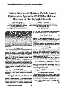
grid network (2-dimensional lattice) where each particle is connected to its four neighbor particles (above, below, right and left particles). Figure 2.4 illustrates the different neighborhood topologies.
28
(a) Star topology
(b) Ring Topology
(c) Von Neumann Topology
Figure 2.4. A diagrammatic representation of neighborhood topologies
The choice of neighborhood topology has a profound effect on the propagation of the best solution found by the swarm. Using the gbest model the propagation is very fast (i.e. all the particles in the swarm will be affected by the best solution found in iteration t, immediately in iteration t + 1 ). This fast propagation may result in the premature convergence problem discussed in Section 2.5.6. However, using the ring and Von Neumann topologies will slow down the convergence rate because the best solution found has to propagate through several neighborhoods before affecting all particles in the swarm. This slow propagation will enable the particles to explore more areas in the search space and thus decreases the chance of premature convergence.
2.6.4 The Binary PSO Kennedy and Eberhart [1997] have adapted the PSO to search in binary spaces. For the binary PSO, the component values of xi, yi and ˆy i are restricted to the set {0, 1}. The velocity, vi, is interpreted as a probability to change a bit from 0 to 1, or from 1 to 0 when updating the position of particles. Therefore, the velocity vector remains continuous-valued. Since each vi, j ∈ ℜ , a mapping needs to be defined from vi,j to a
29
probability in the range [0, 1]. This is done by using a sigmoid function to squash velocities into a [0, 1] range. The sigmoid function is defined as
sig (v) =
1 1 + e −v
(2.14)
The equation for updating positions (equation (2.10)) is then replaced by the probabilistic update equation [Kennedy and Eberhart 1997]:
0 xi, j (t + 1) = 1
if r3, j (t ) ≥ sig (vi, j (t + 1)) if r3, j (t ) < sig (vi, j (t + 1))
(2.15)
where r3, j (t ) ~ U (0,1) . It can be observed from equation (2.15) that if sig(vi,j) = 0 then xi,j = 0. This situation occurs when vi,j < -10. Furthermore, sig(vi,j) will saturate when vi,j > 10 [Van den Bergh 2002]. To avoid this problem, it is suggested to set vi,j ∈ [-4,4] and to use velocity clamping with Vmax = 4 [Kennedy and Eberhart 2001]. PSO has also been extended to deal with arbitrary discrete representation [Yoshida et al. 1999; Fukuyama and Yoshida 2001; Venter and SobieszczanskiSobieski 2002; Al-kazemi and Mohan 2000; Mohan and Al-Kazemi 2001]. These extensions are generally achieved by rounding xi,j to its closest discrete value after applying position update equation (2.10) [Venter and Sobieszczanski-Sobieski 2002].
30
2.6.5 PSO vs. GA A PSO is an inherently continuous algorithm where as a GA is an inherently discrete algorithm [Venter and Sobieszczanski-Sobieski 2002]. Experiments conducted by Veeramachaneni et al. [2003] showed that a PSO performed better than GAs when applied on some continuous optimization problems. Furthermore, according to Robinson et al. [2002], a PSO performed better than GAs when applied to the design of a difficult engineering problem, namely, profiled corrugated horn antenna design [Diaz and Milligan 1996]. In addition, a binary PSO was compared with a GA by Eberhart and Shi [Comparison 1998] and Kennedy and Spears [1998]. The results showed that binary PSO is generally faster, more robust and performs better than binary GAs, especially when the dimension of a problem increases. Hybrid
approaches
combining
PSO
and
GA
were
proposed
by
Veeramachaneni et al. [2003] to optimize the profiled corrugated horn antenna. The hybridization works by taking the population of one algorithm when it has made no fitness improvement and using it as the starting population for the other algorithm. Two versions were proposed: GA-PSO and PSO-GA. In GA-PSO, the GA population is used to initialize the PSO population. For PSO-GA, the PSO population is used to initialize the GA population. According to Veeramachaneni et al. [2003], PSO-GA performed slightly better than PSO. Both PSO and PSO-GA outperformed both GA and GA-PSO. Some of the first applications of PSO were to train Neural Networks (NNs), including NNs with product units. Results have shown that PSO is better than GA and other training algorithms [Eberhart and Shi, Evolving 1998; Van den Bergh and Engelbrecht 2000; Ismail and Engelbrecht 2000].
31
According to Shi and Eberhart [1998], the PSO performance is insensitive to the population size (however, the population size should not be too small). This observation was verified by Løvberg [2002] and Krink et al. [2002]. Consequently, PSO with smaller swarm sizes perform comparably to GAs with larger populations. Furthermore, Shi and Eberhart observed that PSO scales efficiently. This observation was verified by Løvberg [2002].
2.6.6 PSO and Constrained Optimization Most engineering problems are constrained problems. However, the basic PSO is only defined for unconstrained problems. One way to allow the PSO to optimize constrained problems is by adding a penalty function to the original fitness function (as discussed in Section 2.5.2). In this thesis, a constant penalty function (empirically set to 106) is added to the original fitness function for each particle with violated constraints. More recently, a modification to the basic PSO was proposed by Venter and Sobieszczanski-Sobieski [2002] to penalize particles with violated constraints. The idea is to reset the velocity of each particle with violated constraints. Therefore, these particles will only be affected by yi and ˆy . According to Venter and Sobieszczanski-Sobieski [2002], this modification has a significant positive effect on the performance of PSO. Other PSO approaches dealing with constrained problems can be found in El-Gallad et al. [2001], Hu and Eberhart [Solving 2002], Schoofs and Naudts [2002], Parsopoulos and Vrahatis [2002], Coath et al. [2003] and Gaing [2003].
32
2.6.7 Drawbacks of PSO PSO and other stochastic search algorithms have two major drawbacks [Løvberg 2002]. The first drawback of PSO, and other stochastic search algorithms, is that the swarm may prematurely converge (as discussed in Section 2.5.6). According to Angeline [Evolutionary 1998], although PSO finds good solutions much faster than other evolutionary algorithms, it usually can not improve the quality of the solutions as the number of iterations is increased. PSO usually suffers from premature convergence when strongly multi-modal problems are being optimized. The rationale behind this problem is that, for the gbest PSO, particles converge to a single point, which is on the line between the global best and the personal best positions. This point is not guaranteed to be even a local optimum. Proofs can be found in Van den Bergh [2002]. Another reason for this problem is the fast rate of information flow between particles, resulting in the creation of similar particles (with a loss in diversity) which increases the possibility of being trapped in local optima [Riget and Vesterstrøm 2002]. Several modifications of the PSO have been proposed to address this problem. Two of these modifications have already been discussed, namely, the inertia weight and the lbest model. Other modifications are discussed in the next section. The second drawback is that stochastic approaches have problem-dependent performance. This dependency usually results from the parameter settings of each algorithm. Thus, using different parameter settings for one stochastic search algorithm result in high performance variances. In general, no single parameter setting exists which can be applied to all problems. This problem is magnified in PSO where modifying a PSO parameter may result in a proportionally large effect [Løvberg 2002]. For example, increasing the value of the inertia weight, w, will increase the speed of the particles resulting in more exploration (global search) and less 33
exploitation (local search). On the other hand, decreasing the value of w will decrease the speed of the particle resulting in more exploitation and less exploration. Thus finding the best value for w is not an easy task and it may differ from one problem to another. Therefore, it can be concluded that the PSO performance is problemdependent. One solution to the problem-dependent performance of PSO is to use selfadaptive parameters. In self-adaptation, the algorithm parameters are adjusted based on the feedback from the search process [Løvberg 2002]. Bäck [1992] has successfully applied self-adaptation on GAs. Self-adaptation has been successfully applied to PSO by Clerc [1999], Shi and Eberhart [2001], Hu and Eberhart [Adaptive 2002], Ratnaweera et al. [2003] and Tsou and MacNish [2003], Yasuda et al. [2003] and Zhang et al. [2003]. The problem-dependent performance problem can be addressed through hybridization. Hybridization refers to combining different approaches to benefit from the advantages of each approach [Løvberg 2002]. Hybridization has been successfully applied to PSO by Angeline [1998], Løvberg [2002], Krink and Løvbjerg [2002], Veeramachaneni et al. [2003], Reynolds et al. [2003], Higashi and Iba [2003] and Esquivel and Coello Coello [2003].
2.6.8 Improvements to PSO The improvements presented in this section are mainly trying to address the problem of premature convergence associated with the original PSO. These improvements usually try to solve this problem by increasing the diversity of solutions in the swarm.
34
Constriction Factor
Clerc [1999] and Clerc and Kennedy [2001] proposed using a constriction factor to ensure convergence. The constriction factor can be used to choose values for w, c1 and c2 to ensure that the PSO converges. The modified velocity update equation is defined as follows:
vi, j (t + 1) = χ (vi, j (t ) + c1 r1, j (t )( y i, j (t ) − xi, j (t )) + c 2 r2, j (t )( ˆy j (t ) − xi, j (t ))),
(2.16)
where χ is the constriction factor defined as follows:
χ=
2 2 − ϕ − ϕ 2 − 4ϕ
,
and ϕ = c1 + c 2 , ϕ > 4 . Eberhart and Shi [2000] showed imperically that using both the constriction factor and velocity clamping generally improves both the performance and the convergence rate of the PSO.
Guaranteed Convergence PSO (GCPSO)
The original versions of PSO as given in Section 2.6.1, may prematurely converge when xi = yi = ˆy , since the velocity update equation will depend only on the term
wvi(t) [Van den Bergh and Engelbrecht 2002; Van den Bergh 2002]. To overcome this problem, a new version of PSO with guaranteed local convergence was introduced by Van den Bergh [2002], namely GCPSO. In GCPSO, the global best particle with index τ is updated using a different velocity update equation, namely 35
vτ , j (t + 1) = − xτ , j (t ) + ˆy j (t ) + wvτ , j (t ) + ρ (t )(1 − 2 r2 , j (t ))
(2.17)
which results in a position update equation of
xτ , j (t + 1) = ˆy j (t ) + w vτ , j (t ) + ρ (t )(1 − 2 r2 , j (t ))
(2.18)
The term –xτ resets the particle's position to the global best position ˆy ; w vτ (t ) signifies a search direction, and ρ (t )(1 − 2 r2 , j (t )) adds a random search term to the equation. The term ρ (t ) defines the area in which a better solution is searched.
The value of ρ (0) is initialized to 1.0, with ρ (t + 1) defined as 2 ρ (t) if # successes > s c ρ (t + 1) = 0.5ρ (t) if # failures > f c ρ (t) otherwise
(2.19)
A failure occurs when f ( ˆy (t )) ≥ f ( ˆy (t - 1)) (in the case of a minimization problem) and the variable #failures is subsequently incremented (i.e. no apparent progress has been made). A success then occurs when f ( ˆy (t )) < f ( ˆy (t - 1)) . Van den Bergh [2002] suggests learning the control threshold values fc and sc dynamically. That is,
s (t ) + 1 s c (t + 1) = c s c (t )
if # failures (t + 1) > f c otherwise
f (t ) + 1 f c (t + 1) = c f c (t )
if # success(t + 1) > s c otherwise
36
(2.20)
(2.21)
This arrangement ensures that it is harder to reach a success state when multiple failures have been encountered. Likewise, when the algorithm starts to exhibit overly confident convergent behavior, it is forced to randomly search a smaller region of the search space surrounding the global best position. For equation (2.19) to be well defined, the following rules should be implemented:
#successes(t+1) > #successes(t) ⇒ #failures(t+1) = 0 #failures(t+1) > #failures(t) ⇒ #successes(t+1) = 0
Van den Bergh suggests repeating the algorithm until ρ becomes sufficiently small, or until stopping criteria are met. Stopping the algorithm once ρ reaches a lower bound is not advised, as it does not necessarily indicate that all particles have converged – other particles may still be exploring different parts of the search space. It is important to note that, for the GCPSO algorithm, all particles except for the global best particle still follow equations (2.8) and (2.10). Only the global best particle follows the new velocity and position update equations. According to Van den Bergh [2002] and Peer et al. [2003], GCPSO generally performs better than PSO when applied to benchmark problems. This improvement in performance is especially noticeable when PSO and GCPSO are applied to unimodal functions, but the performance of both algorithms was generally comparable for multi-modal functions [Van den Bergh 2002]. Furthermore, due to its fast rate of convergence, GCPSO is slightly more likely to be trapped in local optima [Van den Bergh 2002]. However, it has gauaranteed local convergence whereas the original PSO does not.
37
Multi-start PSO (MPSO)
Van den Bergh [2002] proposed MPSO which is an extension to GCPSO in order to make it a global search algorithm. MPSO works as follows: 1. Randomly initialize all the particles in the swarm. 2. Apply the GCPSO until convergence to a local optimum. Save the position of this local optimum. 3. Repeat Steps 1 and 2 until some stopping criteria are satisfied.
In Step 2, the GCPSO can be replaced by the original PSO. Several versions of MPSO were proposed by Van den Bergh [2002] based on the way used to determine the convergence of GCPSO. One good approach is to measure the rate of change in the objective function as follows: f ratio =
f ( ˆy (t )) − f ( ˆy (t − 1)) f ( ˆy (t ))
If fratio is less than a user-specified threshold then a counter is incremented. The swarm is assumed to have converged if the counter reaches a certain threshold [Van den Bergh 2002]. According to Van den Bergh [2002], MPSO generally performed better than GCPSO in most of the tested cases. However, the performance of MPSO degrades significantly as the number of dimensions in the objective function increases [Van den Bergh 2002].
Attractive and Repulsive PSO (ARPSO)
ARPSO [Riget and Vesterstrøm 2002] alternates between two phases: attraction and repulsion based on a diversity measure. In the attraction phase, ARPSO uses PSO to allow fast information flow, as such particles attract each other and thus the diversity 38
reduces. It was found that 95% of fitness improvements were achieved in this phase. This observation shows the importance of low diversity in fine tuning the solution. In the repulsion phase, particles are pushed away from the best solution found so far thereby increasing diversity. Based on the experiments conducted by Riget and Vesterstrøm [2002] ARPSO outperformed PSO and GA in most of the tested cases.
Selection
A hybrid approach combining PSO with a tournament selection method was proposed by Angeline [Using Selection 1998]. Each particle is ranked based on its performance against a randomly selected group of particles. For this purpose, a particle is awarded one point for each opponent in the tournament for which the particle has a better fitnss. The population is then sorted in decending order according to the points accumulated. The bottom half of the population is then replaced by the top half. This step reduces the diversity of the population. The results showed that the hybrid approach performed better than the PSO (without w and χ ) for unimodal functions. However, the hybrid approach performed worse than the PSO for functions with many local optima. Therefore, it can be concluded that although the use of a selection method improves the exploitation capability of the PSO, it reduces its exploration capability [Ven den Bergh 2002]. Hence, using a selection method with PSO may result in premature convergence.
Breeding
Løvberg et al. [2001] proposed a modification to PSO by using an arithmetic crossover operator (discussed in Section 2.5.4), referred to as a breeding operator, in order to improve the convergence rate of PSO. Each particle in the swarm is assigned
39
a user-defined breeding probability. Based on these probabilities, two parent particles are randomly selected to create offspring using the arithmetic crossover operator. Offspring replace the parent particles. The personal best position of each offspring particle is initialized to its current position (i.e. yi = xi), and its velocity is set as the sum of the two parent's velocities normalized to the original length of each parent velocity. The process is repeated until a new swarm of the same size has been generated. PSO with breeding generally performed better than the PSO when applied to multi-modal functions [Løvberg et al. 2001].
Mutation
Recently, Higashi and Iba [2003] proposed hybriding PSO with Gaussian mutation. Similarly, Esquivel and Coello Coello [2003] proposed hybridizing lbest- and gbestPSO with a powerful diversity maintenance mechanism, namely, a non-uniform mutation operator discussed in section 2.5.5 to solve the premature convergence problem of PSO. According to Esquivel and Coello Coello [2003] the hybrid approach of lbest PSO and the non-uniform mutation operator outperformed PSO and GCPSO in all of the conducted experiments.
Dissipative PSO (DPSO)
DPSO was proposed by Xie et al. [2002] to add random mutation to PSO in order to prevent premature convergence. DPSO introduces negative entropy via the addition of randomness to the particles (after executing equation (2.8) and (2.10)) as follows: If (r1(t) < cv) then vi,j(t + 1) = r2(t)Vmax If (r3(t) < cl) then xi,j(t + 1) = R(t)
40
where r1(t) ~ U(0,1), r2(t) ~ U(0,1) and r3(t) ~ U(0,1); cv and cv are chaotic factors in the range [0,1] and R(t) ~ U(Zmin,Zmax) where Zmin and Zmax are the lower and upper bound of the search space. The results showed that DPSO performed better than PSO when applied to the benchmarks problems [Xie et al. 2002].
Differential Evolution PSO (DEPSO)
DEPSO [Zhang and Xie 2003] uses a differential evolution (DE) operator [Storn and Price 1997] to provide the mutations. A trait point &y&i (t ) is calculated as follows:
If (r1(t) < pc OR j = kd) then &y&i, j (t ) = ˆy j (t ) +
( y1, j (t ) − y 2 , j (t )) + ( y 3, j (t ) − y 4 , j (t ))
(2.23)
2
where r1(t) ~ U(0,1), kd ~ U(1,Nd), and y1 (t ) , y 2 (t ) , y 3 (t ) and y 4 (t ) are randomly chosen
from
the
set
of
personal
best
positions.
Then,
yi (t ) = &y&i (t ), only if f ( &y&i (t )) < f ( yi (t )) . The rationale behind mutating yi (t ) instead of xi (t ) is to avoid disorganization of the swarm. DEPSO works by alternating between the original PSO and the DE operator such that equations (2.8) and (2.10) are used in the odd iterations and equation (2.23) is used is in the even iterations. According to Zhang and Xie [2003], DEPSO generally performed better than PSO, DE, GA, ES, DPSO and fuzzy-adaptive PSO when applied to the benchmark functions.
41
Craziness
To avoid premature convergence, Kennedy and Eberhart [1995] introduced the use of a craziness operator with PSO. However, they concluded that this operator may not be necessay. More recently, Venter and Sobieszczanski-Sobieski [2002] reintroduced the craziness operator to PSO. In each iteration, a few particles far from the center of the swarm are selected. The positions of these particles are then randomly changed while their velocities are initialized to the cognitive velocity component, i.e.
vi, j (t + 1) = c1r1, j (t )( yi, j (t ) − xi, j (t ))
(2.24)
According to Venter and Sobieszczanski-Sobieski [2002], the proposed craziness operator does not seem to have a big influence on the performance of PSO.
The LifeCycle Model
A self-adaptive heuristic search algorithm, called LifeCycle, was proposed by Krink and Løvbjerg [2002]. LifeCycle is a hybrid approach combing PSO, GA and HillClimbing approaches. The motivation for LifeCycle is to gain the benefits of PSO, GA and Hill-Climbing in one algorithm. In LifeCycle, the individuals (representing potential solutions) start as PSO particles, then depending on their performance (in searching for solutions) can change into GA individuals, or Hill-Climbers. Then, they can return back to particles. This process is repeated until convergence. The LifeCycle was compared with PSO, GA and Hill-Climbing [Krink, and Løvbjerg 2002] and has generally shown good performance when applied to the benchmark problems. However, PSO performed better than (or comparable to) the LifeCycle in three out of five benchmark problems. Another hybrid approach proposed by Veeramachaneni et
42
al. [2003] combining PSO and GA has already been discussed in Section 2.6.5. From the experimental results of Krink and Løvbjerg [2002] and Veeramachaneni et al. [2003], it can be observed that the original PSO performed well compared to their more complicated hybrid approaches.
Multi-Swarm (or subpopulation)
The idea of using several swarms instead of one swarm was applied to PSO by Løvberg et al. [2001] and Van den Bergh and Engelbrecht [2001]. The approach proposed by Løvberg et al. [2001] is an extension of PSO with the breeding operator discussed above. The idea is to divide the swarm into several swarms. Each swarm has its own global best particles. The only interaction between the swarms occurs when the breeding selects two particles to mate from different swarms. The results in Løvberg et al. [2001] showed that this approach did not improve the performance of PSO. The expected reasons are [Jensen and Kristensen 2002]:
•
The authors split a swarm of 20 particles into six different swarms. Hence, each swarm contains a few particles. Swarms with few particles have little diversity and therefore little exploration power.
•
No action has been taken to prevent swarms from being too similar to each other.
The above problems were addressed by Jensen and Kristensen [2002]. The modified approach works by using two swarms (each with a size of 20 particles) and keeping them away from each other either by randomly spreading the swarm (with the worst performance) over the search space or by adding a small mutation to the positions of the particles in this swarm. The approach using the mutation technique generally
43
performed better than PSO when applied to the benchmark problems [Jensen and Kristensen 2002]. However, one drawback of this approach is the fact that the decision of whether two swarms are too close to each other is very problem dependent [Jensen and Kristensen 2002].
Self-Organized Criticality (SOC PSO)
In order to increase the population diversity to avoid premature convergence, Løvberg and Krink [2002] extended PSO with Self Organized Criticality (SOC). A measure, called criticality, of how close particles are to each other is used to relocate the particles and thus increase the diversity of the swarm. A particle with a high criticality disperses its criticality by increasing the criticality of a user-specified number of particles, CL, in its neighborhood by 1. Then, the particle reduces its own criticality value by CL. The particle then relocates itself. Two types of relocation were investigated: the first re-initializes the particle, while the second pushes the particle with high criticality a little further in the search space. According to Løvberg and Krink [2002], the first relocation approach produced better results when applied to the tested functions. SOC PSO outperformed PSO in one case out of the four cases used in the experiments. However, adding a tenth of the criticality value of a particle to its own inertia (w was set to 0.2) results in a significant improvement of the SOC PSO compared to PSO [Løvberg and Krink 2002].
Fitness-Distance Ratio based PSO (FDR-PSO)
Recently, Veeramachaneni et al. [2003] proposed a major modification to the way PSO operates by adding a new term to the velocity update equation. The new term
44
allows each particle to move towards a particle in its neighborhood that has a better personal best position. The modified velocity update equation is defined as:
vi, j (t + 1) = wvi, j (t ) + ψ 1 ( yi, j (t ) − xi, j (t )) + ψ 2 ( ˆy j (t ) − xi, j (t )) + ψ 3 ( yη , j (t ) − xi, j (t ))
(2.25)
where ψ 1 , ψ 2 and ψ 3 are user-specified parameters and each yη , j (t ) is chosen by maximizing
f ( x i (t )) − f ( yη (t ))
(2.26)
y η, j (t ) − xi, j (t )
where |.| represents the absolute value. According to Veeramachaneni et al. [2003], FDR-PSO decreases the possibility of premature convergence and thus is less likely to be trapped in local optima. In addition, FDR-PSO (using ψ 1 = ψ 2 = 1 and ψ 3 = 2 ) outperformed PSO and several other variations of PSO, namely, ARPSO, DPSO, SOC PSO and Multi Swarm PSO [Løvberg et al. 2001], in different tested benchmark problems [Veeramachaneni et al. 2003].
2.7 Ant Systems Another population-based stochastic approach is Ant Systems. Ant Systems were first introduced by Dorigo [1992] and Dorigo et al. [1991] to solve some difficult combinatorial optimization problems [Dorigo et al. 1999]. Ant systems were inspired by the observation of real ant colonies. In real ant colonies, ants communicate with
45
each other indirectly through depositing a chemical substance, called pheromone. Ants use, for example, pheromones to find the shortest path to food. This indirect way of communication via pheromones is called stigmergy [Dorigo et al. 1999]. Using Ant Colony Optimization (ACO), a finite size colony of artificial ants cooperate with each other via stigmergy to find quality solutions to optimization problems. Good solutions result from the cooperation of the artificial ants. ACO was applied to a wide range of optimization problems such as the traveling salesman problem, and routing and load balancing in packet switched networks with encouraging results [Dorigo et al. 1999]. More details about Ant Systems and their applications can be found in Bonabeau et al. [1999] and Dorigo and Di Caro [1999]. Ant systems and their applications are outside the scope of this thesis.
2.8 Conclusions This chapter provided a short overview of optimization and optimization methods with a special emphasis on PSO. From the discussed methods, PSO (and GA for comparison purposes) is used in this thesis to optimize a set of problems in the field of pattern recognition and image processing. These problems are introduced in the next chapter.
46
Chapter 3 Problem Definition
This chapter reviews the problems addressed in this thesis in sufficient detail. First the clustering problem is defined and different clustering concepts and approaches are discussed. This is followed by defining image segmentation in addition to presenting various image segmentation methods. A survey of color image quantization and approaches to quantization are then presented. This is followed by a brief introduction to spectral unmixing.
3.1 The Clustering Problem
Data clustering is the process of identifying natural groupings or clusters within multidimensional data based on some similarity measure (e.g. Euclidean distance) [Jain et al. 1999; Jain et al. 2000]. It is an important process in pattern recognition and machine learning [Hamerly and Elkan 2002]. Furthermore, data clustering is a central process in Artificial Intelligence (AI) [Hamerly 2003]. Clustering algorithms are used in many applications, such as image segmentation [Coleman and Andrews 1979; Jain and Dubes 1988; Turi 2001], vector and color image quantization [Kaukoranta et al. 1998; Baek et al. 1998; Xiang 1997], data mining [Judd et al. 1998], compression [Abbas and Fahmy 1994], machine learning [Carpineto and Romano 1996], etc. A cluster is usually identified by a cluster center (or centroid) [Lee and Antonsson 2000]. Data clustering is a difficult problem in unsupervised pattern recognition as the clusters in data may have different shapes and sizes [Jain et al. 2000].
47
3.1.1 Definitions The following terms are used in this thesis:
•
A pattern (or feature vector), z, is a single object or data point used by the clustering algorithm [Jain et al. 1999].
•
A feature (or attribute) is an individual component of a pattern [Jain et al. 1999].
•
A cluster is a set of similar patterns, and patterns from different clusters are not similar [Everitt 1974].
•
Hard (or Crisp) clustering algorithms assign each pattern to one and only one cluster.
•
Fuzzy clustering algorithms assign each pattern to each cluster with some degree of membership.
•
A distance measure is a metric used to evaluate the similarity of patterns [Jain et al. 1999].
The clustering problem can be formally defined as follows (Veenman et al. 2003): Given a data set Z = {z1 , z 2 ,K , z p ,K , z N p } where zp is a pattern in the Nd-dimensional feature space, and Np is the number of patterns in Z, then the clustering of Z is the partitioning of Z into K clusters {C1, C2,…,CK} satisfying the following conditions:
•
Each pattern should be assigned to a cluster, i.e.
∪ kK=1 C k = Z •
Each cluster has at least one pattern assigned to it, i.e.
48
C k ≠ φ , k = 1,K , K
•
Each pattern is assigned to one and only one cluster (in case of hard clustering only), i.e.
C k ∩ C kk = φ where k ≠ kk
3.1.2 Similarity Measures As previously mentioned, clustering is the process of identifying natural groupings or clusters within multidimensional data based on some similarity measure. Hence, similarity measures are fundamental components in most clustering algorithms [Jain et al. 1999]. The most popular way to evaluate a similarity measure is the use of distance measures. The most widely used distance measure is the Euclidean distance defined as
d (zu , z w ) =
Nd
∑ (z j =1
u, j
− z w, j ) 2 = z u − z w
(3.1)
Euclidean distance is a special case (when α = 2) of the Minkowski metric [Jain et al. 1999] defined as
Nd
d α ( z u , z w ) = (∑ ( z u, j − z w, j ) α )1 / α = z u − z w
α
(3.2)
j =1
When α = 1, the measure is referred to as the Manhattan distance [Hamerly 2003].
49
Clustering data of high dimensionality using the Minkowski metric is usually not efficient because the distance between the patterns increases with increase in dimensionality. Hence, the concepts of near and far become weaker [Hamerly 2003]. Furthermore, for the Minkowski metric, the largest-scaled feature tends to dominate the other features. This can be solved by normalizing the features to a common range [Jain et al. 1999]. One way to do this is by using the cosine distance (or vector dot product) which is the sum of the product of each component from two vectors defined as
Nd
< zu , z w > =
∑z j =1
u, j
z w, j (3.3)
zu z w
where < z u ,z w > ∈ [-1,1]. The cosine distance is actually not a distance but rather a similarity metric. In other words, the cosine distance measures the difference in the angle between two vectors not the difference in the magnitude between two vectors. The cosine distance is suitable for clustering data of high dimensionality [Hamerly 2003].
Another distance measure is the Mahalanobis distance defined as
d M ( zu , z w ) = ( zu − z w )Σ −1 ( zu − z w )T
(3.4)
where Σ is the covariance matrix of the patterns. The Mahalanobis distance gives different features different weights based on their variances and pairwise linear
50
correlations. Thus, this metric implicitly assumes that the densities of the classes are multivariate Gaussian [Jain et al. 1999].
3.1.3 Clustering Techniques Most clustering algorithms are based on two popular techniques known as hierarchical and partitional clustering [Frigui and Krishnapuram 1999; Leung et al. 2000]. In the following, an overview of both techniques is presented with an elaborate discussion of popular hierarchical and partitional clustering algorithms.
3.1.3.1 Hierarchical Clustering Techniques Algorithms in this category generate a cluster tree (or dendrogram) by using heuristic splitting or merging techniques [Hamerly 2003]. A cluster tree is defined as "a tree showing a sequence of clustering with each clustering being a partition of the data set" [Leung et al. 2000]. Algorithms that use splitting to generate the cluster tree are called divisive. On the other hand, the more popular algorithms that use merging to generate the cluster tree are called agglomerative. Divisive hierarchical algorithms start with all the patterns assigned to a single cluster. Then, splitting is applied to a cluster in each stage until each cluster consists of one pattern. Contrary to divisive hierarchical algorithms, agglomerative hierarchical algorithms start with each pattern assigned to one cluster. Then, the two most similar clusters are merged together. This step is repeated until all the patterns are assigned to a single cluster [Turi 2001]. Several agglomerative hierarchical algorithms were proposed in the literature which differ in the way that the two most similar clusters are calculated. The two most popular
51
agglomerative hierarchical algorithms are the single link [Sneath and Sokal 1973] and complete link [Anderberg 1973] algorithms. Single link algorithms merge the clusters whose distance between their closest patterns is the smallest. Complete link algorithms, on the other hand, merge the clusters whose distance between their most distant patterns is the smallest [Turi 2001]. In general, complete link algorithms generate compact clusters while single link algorithms generate elongated clusters. Thus, complete link algorithms are generally more useful than single link algorithms [Jain et al. 1999]. Another less popular agglomerative hierarchical algorithm is the centroid method [Anderberg 1973]. The centroid algorithm merges the clusters whose distance between their centroids is the smallest. One disadvantage of the centroid algorithm is that the characteristic of a very small cluster is lost when merged with a very large cluster [Turi 2001]. More details about traditional hierarchical clustering techniques can be found in Everitt [1974]. Recently, a hierarchical clustering approach to simulate the human visual system by modeling the blurring effect of lateral retinal interconnections based on scale space theory has been proposed by Leung et al. [2000]. The following paragraph provides the reader with a good idea about this approach as described by Leung et al. [2000]: "In this approach, a data set is considered as an image with each light point located at a datum position. As we blur this image, smaller light blobs merge into larger ones until the whole image becomes one light blob at a low level of resolution. By identifying each blob with a cluster, the blurring process generates a family of clustering along the hierarchy."
According to Leung et al. [2000], this approach has several advantages, including:
52
•
it is not sensitive to initialization,
•
it is robust in the presence of noise in the data set, and
•
it generates clustering that is similar to that perceived by human eyes.
In general, hierarchical clustering techniques have the following advantages [Frigui and Krishnapuram 1999]: •
the number of clusters need not to be specified a priori, and
•
they are independent of the initial conditions.
However, hierarchical clustering techniques generally suffer from the following drawbacks: •
They are computationally expensive (time complexity is O( N p2 log N p ) and space complexity is O( N p2 ) [Turi 2001]). Hence, they are not suitable for very large data sets.
•
They are static, i.e. patterns assigned to a cluster cannot move to another cluster.
•
They may fail to separate overlapping clusters due to a lack of information about the global shape or size of the clusters.
3.1.3.2 Partitional Clustering Techniques Partitional clustering algorithms divide the data set into a specified number of clusters. These algorithms try to minimize certain criteria (e.g. a square error function) and can therefore be treated as optimization problems. However, these optimization
53
problems are generally NP-hard and combinatorial [Leung et al. 2000]. The advantages of hierarchical algorithms are the disadvantages of the partitional algorithms and vice versa. Because of their advantages, partitional clustering techniques are more popular than hierarchical techniques in pattern recognition [Jain et al. 2000], hence, this thesis concentrates on partitional techniques. Partitional clustering algorithms are generally iterative algorithms that converge to local optima [Hamerly and Elkan 2002]. Employing the general form of iterative clustering used by Hamerly and Elkan [2002], the steps of an iterative clustering algorithm are:
1. Randomly initialize the K cluster centroids 2. Repeat (a) For each pattern, zp, in the data set do Compute its membership u (mk | z p ) to each centroid mk and its weight w(zp) endloop
(b) Recalculate the K cluster centroids, using
mk =
∑ u (m ∀z p
k
∑ u (m ∀z p
| z p ) w( z p ) z p k
(3.5)
| z p ) w( z p )
until a stopping criterion is satisfied.
In the above algorithm, u (mk | z p ) is the membership function which quantifies the membership of pattern zp to cluster k. The membership function, u (mk | z p ) , must satisfy the following constraints:
54
1) u (mk | z p ) ≥ 0, p = 1,…, Np and k = 1,…, K K
2)
∑ u (m k =1
k
| z p ) = 1 , p = 1,…, Np
Crisp clustering algorithms use a hard membership function (i.e. u (mk | z p ) ∈{0,1}), while fuzzy clustering algorithms use a soft member function (i.e. u (mk | z p ) ∈[0,1]) [Hamerly and Elkan 2002]. The weight function, w(zp), in equation (3.5) defines how much influence pattern zp has in recomputing the centroids in the next iteration, where w( z p ) > 0 [Hamerly and Elkan 2002]. The weight function was proposed by Zhang [2000]. Different stopping criteria can be used in an iterative clustering algorithm, for example: •
stop when the change in centroid values are smaller than a user-specified value,
•
stop when the quantization error is small enough, or
•
stop when a maximum number of iterations has been exceeded.
In the following, popular iterative clustering algorithms are described by defining the membership and weight functions in equation (3.5).
The K-means Algorithm
The most widely used partitional algorithm is the iterative K-means approach [Forgy 1965]. The objective function that the K-means optimizes is
55
K
J K − means = ∑
∑d
k =1 ∀z p ∈C k
2
(z p , mk )
(3.6)
Hence, the K-means algorithm minimizes the intra-cluster distance [Hamerly and Elkan 2002]. The K-means algorithm starts with K centroids (initial values for the centroids are randomly selected or derived from a priori information). Then, each pattern in the data set is assigned to the closest cluster (i.e. closest centroid). Finally, the centroids are recalculated according to the associated patterns. This process is repeated until convergence is achieved. The membership and weight functions for K-means are defined as
{
}
1 if d 2 ( z p , m k ) = arg min k d 2 ( z p , m k ) u (m k | z p ) = otherwise 0
(3.7)
w( z p ) = 1
(3.8)
Hence, K-means has a hard membership function. Furthermore, K-means has a constant weight function, thus, all patterns have equal importance [Hamerly and Elkan 2002].
The K-means algorithm has the following main advantages [Turi 2001]: •
it is very easy to implement, and
•
its time complexity is O(Np) making it suitable for very large data sets.
However, the K-means algorithm has the following drawbacks [Davies 1997]: •
the algorithm is data-dependent,
56
•
it is a greedy algorithm that depends on the initial conditions, which may cause the algorithm to converge to suboptimal solutions, and
•
the user needs to specify the number of clusters in advance.
The K-medoids algorithm is similar to K-means with one major difference, namely, the centroids are taken from the data itself [Hamerly 2003]. The objective of Kmedoids is to find the most centrally located patterns within the clusters [Halkidi et al. 2001]. These patterns are called medoids. Finding a single medoid requires O( N p2 ) . Hence, K-medoids is not suitable for moderately large data sets.
The Fuzzy C-means Algorithm
A fuzzy version of K-means, called Fuzzy C-means (FCM) (sometimes called fuzzy K-means), was proposed by Bezdek [1980; 1981]. FCM is based on a fuzzy extension of the least-square error criterion. The advantage of FCM over K-means is that FCM assigns each pattern to each cluster with some degree of membership (i.e. fuzzy clustering). This is more suitable for real applications where there are some overlaps between the clusters in the data set. The objective function that the FCM optimizes is
K
Np
J FCM = ∑∑ u k,q p d 2 ( z p , m k )
(3.9)
k =1 p =1
where q is the fuzziness exponent, with q ≥ 1. Increasing the value of q will make the algorithm more fuzzy; uk,p is the membership value for the pth pattern in the kth cluster satisfying the following constraints: 1) uk, p ≥ 0 , p = 1,…, Np and k = 1,…, K
57
K
2)
∑u k =1
k, p
= 1 , p = 1,…, Np
The membership and weight functions for FCM are defined as [Hamerly and Elkan 2002]
u (m k | z p ) =
z p − mk K
∑z k =1
p
−2 / ( q −1)
− mk
(3.10)
− 2 / ( q −1)
w( z p ) = 1
(3.11)
Hence, FCM has a soft membership function and a constant weight function. In general, FCM performs better than K-means [Hamerly 2003] and it is less affected by the presence of uncertainty in the data [Liew et al. 2000]. However, as in K-means it requires the user to specify the number of clusters in the data set. In addition, it may converge to local optima [Jain et al. 1999]. Krishnapuram and Keller [1993; 1996] proposed a possibilistic clustering algorithm, called possibilistic C-means. Possibilistic clustering is similar to fuzzy clustering; the main difference is that in possibilistic clustering the membership values may not sum to one [Turi 2001]. Possibilistic C-means works well in the presence of noise in the data set. However, it has several drawbacks, namely [Turi 2001], •
it is likely to generate coincident clusters,
•
it requires the user to specify the number of clusters in advance,
•
it converges to local optima, and
•
it depends on initial conditions.
58
The Gaussian Expectation-Maximization Algorithm
Another popular clustering algorithm is the Expectation-Maximization (EM) algorithm [McLachlan and Krishnan 1997; Rendner and Walker 1984; Bishop 1995]. EM is used for parameter estimation in the presence of some unknown data [Hamerly 2003]. EM partitions the data set into clusters by determining a mixture of Gaussians fitting the data set. Each Gaussian has a mean and covariance matrix [Alldrin et al. 2003]. The objective function that the EM optimizes as defined by Hamerly and Elkan [2002] is
Np
K
p =1
k =1
J EM = −∑ log(∑ p( z p | m k ) p(m k ))
(3.12)
where p ( z p | m k ) is the probability of z p given that it is generated by a Gaussian distribution with centroid m k , and p(m k ) is the prior probability of centroid m k . The membership and weight functions for EM are defined as [Hamerly and Elkan 2002]
u (mk | z p ) =
p ( z p | mk ) p (mk )
(3.13)
p( z p )
w( z p ) = 1
(3.14)
Hence, EM has a soft membership function and a constant weight function. The algorithm starts with an initial estimate of the parameters. Then, an expectation step is applied where the known data values are used to compute the expected values of the unknown data [Hamerly 2003]. This is followed by a maximization step where the
59
known and expected values of the data are used to generate a new estimate of the parameters. The expectation and maximization steps are repeated until convergence. Results from Veenman et al. [2002] and Hamerly [2003] showed that Kmeans performs comparably to EM. Furthermore, Aldrin et al. [2003] stated that EM fails on high-dimensional data sets due to numerical precision problems. They also observed that Gaussians often collapsed to delta functions [Alldrin et al. 2003]. In addition, EM depends on the initial estimate of the parameters [Hamerly 2003; Turi 2001] and it requires the user to specify the number of clusters in advance. Moreover, EM assumes that the density of each cluster is Gaussian which may not always be true [Ng et al. 2001].
The K-harmonic Means Algorithm
Recently, Zhang and colleagues [1999; 2000] proposed a novel algorithm called Kharmonic means (KHM), with promising results. In KHM, the harmonic mean of the distance of each cluster center to every pattern is computed. The cluster centroids are then updated accordingly. The objective function that the KHM optimizes is
Np
J KHM = ∑ p =1
K K
∑ k =1
(3.15)
1 z p − mk
α
where α is a user-specified parameter, typically α ≥ 2. The membership and weight functions for KHM are [Hamerly and Elkan 2002]
60
u (m k | z p ) =
z p − mk K
∑z k =1
K
w( z p ) =
∑z k =1
p
p
−α − 2
− mk
− mk
K ∑ z p − mk k =1
(3.16)
−α − 2
−α − 2
−α
(3.17)
2
Hence, KHM has a soft membership function and a varying weight function. KHM assigns higher weights for patterns that are far from all the centroids to help the centroids in covering the data [Hamerly and Elkan 2002]. Contrary to K-means, KHM is less sensitive to initial conditions and does not have the problem of collapsing Gaussians exhibited by EM [Alldrin et al. 2003]. Experiments conducted by Zhang et al. [1999], Zhang [2000] and Hamerly and Elkan [2002] showed that KHM outperformed K-means, FCM (according to Hamerly and Elkan [2002]) and EM.
Hybrid 2
Hamerly and Elkan [2002] proposed a variation of KHM, called Hybrid 2 (H2), which uses the soft membership function of KHM (i.e. equation (3.16)) and the constant weight function of K-means (i.e. equation (3.8)). Hamerly and Elkan [2002] showed that H2 outperformed K-means, FCM and EM. However, KHM, in general, performed slightly better than H2.
K-means, FCM, EM, KHM and H2 are linear time algorithms (i.e. their time complexity is O(Np)) making them suitable for very large data sets. According to
61
Hamerly [2003], FCM, KHM and H2 - all use soft membership functions - are the best available clustering algorithms.
Non-iterative Partitional Algorithms
Another category of unsupervised partitional algorithms includes the non-iterative algorithms. The most widely used non-iterative algorithm is MacQueen's K-means algorithm [MacQueen 1967]. This algorithm works in two phases: the first phase finds the centroids of the clusters, and the second clusters the patterns. Competitive Learning (CL) updates the centroids sequentially by moving the closest centroid toward the pattern being classified [Scheunders, A Comparison 1997]. These algorithms suffer the drawback of being dependent on the order in which the data points are presented. To overcome this problem, data points are presented in a random order [Davies 1997]. In general, iterative algorithms are more effective than noniterative algorithms, since they are less dependent on the order in which data points are presented.
3.1.3.3 Other Clustering Techniques Another type of clustering algorithms includes the Nearest Neighbor clustering algorithm proposed by Lu and Fu [1978]. For each unclassified pattern, the algorithm finds the nearest classified pattern whose distance from the unclassified pattern is less than a pre-specified threshold. The unclassified pattern is then assigned to the cluster of the classified pattern. This process is repeated until all the patterns become classified or no further assignments can occur [Jain et al. 1999].
62
Recently, a new type of clustering algorithms called spectral clustering algorithms [Ng et al. 2001; Bach and Jordan 2003] has been proposed by computer vision researchers and graph theorists. Spectral clustering is based on spectral graph theory [Chung 1997] where a graph representing the data (the graph is analogous to a matrix of the distance between the patterns in the data set) is searched by the spectral clustering algorithm for globally optimal cuts [Hamerly 2003]. One major advantage of spectral clustering is that it can generate arbitrary-shaped clusters. However, spectral clustering suffers from two major drawbacks [Hamerly 2003]: •
It is computationally expensive (its time complexity is O( N 3p + N d N p2 ) ). Hence, they are not suitable for moderately large data sets.
•
It requires the user to specify a kernel width parameter which has a profound effect on the result of the spectral clustering algorithm. Choosing a good value for this parameter is usually difficult.
The mean shift algorithm [Comaniciu and Meer 2002] also automatically finds the number of clusters in a data set and can work with arbitrary shaped clusters. The mean shift algorithm starts with a number of kernel estimators in the input space. These estimators are then repeatedly moved towards areas of higher density. When all the kernels reached stability, all the kernels that are near to each other are grouped together. The data is then segmented based on where each kernel started.
The mean shift algorithm has the following problems, [Hamerly 2003]: •
it has to find a way to group kernels and patterns, and
63
•
as in spectral clustering, the mean shift algorithm requires the user to specify a kernel width parameter which has a profound effect on the result of the algorithm.
3.1.4 Clustering Validation Techniques
The main objective of cluster validation is to evaluate clustering results in order to find the best partitiong of a data set [Halkidi et al. 2001]. Hence, cluster validity approaches are used to quantitatively evaluate the result of a clustering algorithm [Halkidi et al. 2001]. These approaches have representative indices, called validity indices. The traditional approach to determine the "optimum" number of clusters is to run the algorithm repetitively using different input values and to select the partitioning of data resulting in the best validity measure [Halkidi and Vazirgiannis 2001]. Two criteria that have been widely considered sufficient in measuring the quality of data partitioning, are [Halkidi et al. 2001] •
Compactness: patterns in one cluster should be similar to each other and different from patterns in other clusters. The variance of patterns in a cluster gives an indication of compactness.
•
Separation: clusters should be well-separated from each other. The Euclidean distance between cluster centroids gives an indication of cluster separation.
There are several validity indices; a thorough survey of validity indices can be found in Halkidi et al. [2001]. In the following, some representative indices are discussed. Dunn [1974] proposed a well known cluster validity index that identifies compact and well separated clusters. The main goal of Dunn's index is to maximize 64
inter-cluster distances (i.e. separation) while minimizing intra-cluster distances (i.e. increase compactness). The Dunn index is defined as
dist( C k ,C kk ) D = min min k =1,...,K kk = k +1,...,K max diam( C a ) a=1,...,K
(3.18)
where dist( C k ,C kk ) is the dissimilarity function between two clusters Ck and Ckk defined as
dist( C k ,C kk ) =
min
u∈C k ,w∈C kk
d ( u, w ) ,
where d(u, w) is the Euclidean distance between u and v; diam(C) is the diameter of a cluster, defined as diam( C ) = max d ( u , w ) u ,w∈C
An "optimal" value of K is the one that maximizes the Dunn's index. Dunn's index suffers from the following problems [Halkidi et al. 2001]:
•
it is computationally expensive, and
•
it is sensitive to the presence of noise.
Several Dunn-like indices were proposed in Pal and Biswas [1997] to reduce the sensitivity to the presence of noise. Another well known index, proposed by Davies and Bouldin [1979], minimizes the average similarity between each cluster and the one most similar to it. The Davies and Bouldin index is defined as
65
DB =
1 K
diam(C k ) + diam(C kk ) max kk =1,...,K dist (C k ,C kk ) k =1 k ≠ kk K
∑
(3.19)
An "optimal" value of K is the one that minimizes the DB index. Recently, Turi [2001] proposed an index incorporating a multiplier function (to penalize the selection of a small number of clusters) to the ratio between intracluster and inter-cluster distances, with some promising results. The index is defined as
V = ( c × N ( 2,1) + 1) ×
intra inter
(3.20)
where c is a user specified parameter and N(2,1) is a Gaussian distribution with mean 2 and standard deviation of 1. The "intra" term is the average of all the distances between each data point and its cluster centroid, defined as intra =
1 Np
K
∑ ∑ u−m k =1 ∀u∈C k
2 k
This term is used to measure the compactness of the clusters. The "inter" term is the minimum distance between the cluster centroids, defined as 2
inter = min{ m k − m kk }, ∀ k = 1,..., K − 1 and k k = k + 1,..., K . This term is used to measure the separation of the clusters. An "optimal" value of K is the one that minimizes the V index. According to Turi [2001], this index performed better than both Dunn's index and the index of Davies and Bouldin on the tested cases. Two recent validity indices are S_Dbw [Halkidi and Vazirgiannis 2001] and CDbw [Halkidi and Vazirgiannis 2002]. S_Dbw measures the compactness of a data 66
set by the cluster variance, whereas separation is measured by the density between clusters. The S_Dbw index is defined as
S_Dbw = scat ( K ) + Dens_bw( K )
(3.21)
The first term is the average scattering of the clusters which is a measure of compactness of the clusters, defined as scat(K) =
1 K
K
∑ σ (C k =1
k
) σ (Z )
where σ (C k ) is the variance of cluster Ck and σ ( Z ) is the variance of data set Z; ||z|| is defined as ||z|| = (zTz)1/2, where z is a vector. The second term in equation (3.21) evaluates the density of the area between the two clusters in relation to the density of the two clusters. Thus, the second term is a measure of the separation of the clusters, defined as K K density (bk,kk ) 1 Dens_bw( K ) = ∑ ∑ K ( K − 1) k =1 k k =1 max{density (C k ) , density (C kk )} k ≠ k k where bk,kk is the middle point of the line segment defined by mk and mkk. The term density(b) is defined as nk,kk
density (b) = ∑ f ( z ll , b) ll =1
where nk,kk is the total number of patterns in clusters Ck and Ckk (i.e. nk,kk= nk + nkk). The function f(z,b) is defined as 0 f ( z , b) = 1
if d ( z ,b) > σ otherwise
where
67
σ=
K
1 K
∑ σ (C k =1
k
)
An "optimal" value of K is the one that minimizes the S_Dbw index. Halkidi and Vazirgiannis [2001] showed that, in tested cases, S_Dbw successfully found the "optimal" number of clusters whereas other well-known indices often failed to do so. However, S_Dbw does not work properly for arbitrary shaped clusters. To address this problem, Halkidi and Vazirgiannis [2002] proposed a multirepresentative validity index, CDbw, in which each cluster is represented by a userspecified number of points, instead of one representative as is done in S_Dbw. Furthermore, CDbw uses intra-cluster density to measure the compactness of a data set, and uses the density between clusters to measure their separation. More recently, Veenman et al. [2002; 2003] proposed a validity index that minimizes the intra-cluster variability while constraining the intra-cluster variability of the union of the two clusters. The sum of squared error is used to minimize the intra-cluster variability while a minimum variance for the union of two clusters is used to implement the joint intra-cluster variability. The index is defined as K
IV = min ∑ nk Var (C k )
(3.22)
k =1
where nk is the number of patterns in cluster Ck and Var (C k ) =
1 nk
∑z
z p ∈C k
p
− mk
2
such that 2 , ∀C k ,C kk , k ≠ kk Var (C k ∪ C kk ) ≥ σ max 2 is a user-specified parameter. This parameter has a profound effect on the where σ max
final result.
68
The above validity indices are suitable for hard clustering. Validity indices have been developed for fuzzy clustering. The interested reader is referred to Halkidi et al. [2001] for more information.
3.1.5 Determining the Number of Clusters Most clustering algorithms require the number of clusters to be specified in advance [Lee and Antonsson 2000; Hamerly and Elkan 2003]. Finding the "optimum" number of clusters in a data set is usually a challenge since it requires a priori knowledge, and/or ground truth about the data, which is not always available. The problem of finding the optimum number of clusters in a data set has been the subject of several research efforts [Halkidi et al. 2001; Theodoridis and Koutroubas 1999], however, despite the amount of research in this area, the outcome is still unsatisfactory [Rosenberger and Chehdi 2000]. In the literature, many approaches to dynamically find the number of clusters in a data set were proposed. In this section, several dynamic clustering approaches are presented and discussed. ISODATA (Iterative Self-Organizing Data Analysis Technique), proposed by Ball and Hall [1967], is an enhancement of the K-means algorithm (K-means is sometimes referred to as basic ISODATA [Turi 2001]). ISODATA is an iterative procedure that assigns each pattern to its closest centroids (as in K-means). However, ISODATA has the ability to merge two clusters if the distance between their centroids is below a user-specified threshold. Furthermore, ISODATA can split elongated clusters into two clusters based on another user-specified threshold. Hence, a major advantage of ISODATA compared to K-means is the ability to determine the number of clusters in a data set. However, ISODATA requires the user to specify the values of
69
several parameters (e.g. the merging and splitting thresholds). These parameters have a profound effect on the performance of ISODATA making the result subjective [Turi 2001]. Dynamic Optimal Cluster-seek (DYNOC) [Tou 1979] is a dynamic clustering algorithm which is similar to ISODATA. DYNOC maximizes the ratio of the minimum inter-cluster distance to the maximum intra-cluster distance. This is done by an iterative procedure with the added capability of splitting and merging. However, as in ISODATA, DYNOC requires the user to specify a value for a parameter that determines whether splitting is needed [Turi 2001]. Snob [Wallace 1984; Wallace and Dowe 1994] uses various methods to assign objects to clusters in an intelligent manner [Turi 2001]. After each assignment, a means of model selection called the Wallace Information Measure (also known as the Minimum Message Length) [Wallace and Boulton 1968; Oliver and Hand 1994] is calculated and based on this calculation the assignment is accepted or rejected. Snob can split/merge and move points between clusters, thereby allowing it to determine the number of clusters in a data set. Bischof et al. [1999] proposed an algorithm based on K-means which uses a similar concept to the Wallace Information Measure called the Minimum Description Length [Rissanen 1978] framework. The algorithm starts with a large value for K and proceeds to remove centroids when this removal results in a reduction of the description length. K-means is used between the steps that reduce K. Modified Linde-Buzo-Gray (MLBG), proposed by Rosenberger and Chehdi [2000], improves K-means by automatically finding the number of clusters in data set by using intermediate results. MLBG is an iterative procedure that starts with K clusters. In each iteration, a cluster, Ck, maximizing an intra-cluster distance measure
70
is chosen for splitting. Two centroids are generated from the splitting process. The first centroid, m1, is initialized to the centroid of the original cluster, Ck. The second cluster centroid, m2, is chosen to be the pattern in Ck which is the most distant from m1. K-means is then applied on the new K+1 centroids. The new set of centroids is
accepted if it satisfies an evaluation criterion based on a dispersion measure. This process is repeated until no valid partition of the data can be obtained. One of the main problems with MLBG is that it requires the user to specify the values of four parameters, which have a profound effect on the resultant number of clusters. Pelleg and Moore [2000] proposed another K-means based algorithm, called X-means that uses model selection. X-means starts by setting the number of clusters, K, to be the minimum number of clusters in the data set (e.g. K = 1). Then, K-means is applied on the K clusters. This is followed by a splitting process based on the Bayesian Information Criterion (BIC) [Kass and Wasserman 1995] defined as
K ( N d + 1) BIC (C | Z ) = ˆl ( Z | C ) − log N p 2
(3.23)
where lˆ ( Z | C ) is the log-likelihood of the data set Z according to model C. If the splitting process improves the BIC score the resulting split is accepted, otherwise it is rejected. Other scoring functions can also be used. These two steps are repeated until a user-specified upper bound of K is reached. X-means searches over the range of values of K and reports the value with the best BIC score. Recently, Huang [2002] proposed SYNERACT as an alternative approach to ISODATA. SYNERACT combines K-means with hierarchical descending approaches
71
to overcome the drawbacks of K-means mentioned previously. Three concepts used by SYNERACT are: •
a hyperplane to split up a cluster into two smaller clusters and compute their centroids,
•
iterative clustering to assign pixels into available clusters, and
•
a binary tree to store clusters generated from the splitting process.
According to Huang [2002], SYNERACT is faster than and almost as accurate as ISODATA. Furthermore, it does not require the number of clusters and initial location of centroids to be specified in advance. However, SYNERACT requires the user to specify the values of two parameters that affect the splitting process. Veenman et al. [2002] proposed a partitional clustering algorithm that finds the number of clusters in a data set by minimizing the clustering validity index defined in equation (3.22). This algorithm starts by initializing the number of clusters equal to the number of patterns in the data set. Then, iteratively, the clusters are split or merged according to a series of tests based on the validity index. According to Veenman et al. [2002], the proposed approach performed better than both K-means and EM algorithms. However, the approach suffers from the following drawbacks, namely •
it is computationally expensive, and
•
it requires the user to specify a parameter for the validity index (already discussed in Section 3.1.4) which has a significant effect on the final results (although the authors provide a method to help the user in finding a good value for this parameter).
72
More recently, Hamerly and Elkan [2003] proposed another approach based on Kmeans, called G-means. G-means starts with a small value for K, and with each iteration splits up the clusters whose data do not fit a Gaussian distribution. Between each round of splitting, K-means is applied to the entire data set in order to refine the current solution. According to Hamerly and Elkan [2003], G-means works better than X-means, however, it works only for data having spherical and/or elliptical clusters. G-means is not designed to work for arbitrary-shaped clusters [Hamerly 2003]. Gath and Geva [1989] proposed an unsupervised fuzzy clustering algorithm based on a combination of FCM and fuzzy maximum likelihood estimation. The algorithm starts by initializing K to a user-specified lower bound of the number of clusters in the data set (e.g. K = 1). A modified FCM (that uses an unsupervised learning process to initialize the K centroids) is first applied to cluster the data. Using the resulting centroids, a fuzzy maximum likelihood estimation algorithm is then applied. The fuzzy maximum likelihood estimation algorithm uses an "exponential" distance measure based on maximum likelihood estimation [Bezdek 1981] instead of the Euclidean distance measure, because the exponential distance measure is more suitable for hyper-ellipsoidal clusters. The quality of the resulting clusters is then evaluated using a clustering validity index that is mainly based on a hyper-volume criterion which measures the compactness of a cluster. K is then incremented and the algorithm is repeated until a user-specified upper bound of K is reached. The value of K resulting in the best value of the validity index is considered to be the "optimal" number of clusters in the data set. Gath and Geva [1989] stated that their algorithm works well in cases of large variability of cluster shapes. However, the algorithm becomes more sensitive to local optima as the complexity increases. Furthermore, because of the exponential function, floating point overflows may occur [Su 2002].
73
Lorette et al. [2000] proposed an algorithm based on fuzzy clustering to dynamically determine the number of clusters in a data set. In this thesis, the proposed algorithm is referred as the Unsupervised Fuzzy Clustering (UFC) algorithm. A new objective function was proposed for this purpose, defined as
K
Np
K
J UFC = ∑∑ u k,q p d 2 ( z p , m k ) − β ∑ p k log( p k ) k =1 p =1
(3.24)
k =1
where q is the fuzziness exponent, uk,p is the membership value for the pth pattern in the kth cluster, β is a parameter that decreases as the run progresses, and pk is the a priori probability of cluster Ck defined as
pk =
1 Np
Np
∑u p =1
(3.25)
k, p
The first term of equation (3.24) is the objective function of FCM which is minimized when each cluster consists of one pattern. The second term is an entropy term that is minimized when all the patterns are assigned to one cluster. Lorette et al. [2000] use this objective function to derive new update equations for the membership and centroid parameters. The algorithm starts with a large number of clusters. Then, the membership values and centroids are updated using the new update equations. This is followed by applying equation (3.25) to update the a priori probabilities. If p k < ε then cluster k is discarded; ε is a user-specified parameter. This procedure is repeated until
74
convergence. The drawback of this approach is that it requires the parameter ε to be specified in advance. The performance of the algorithm is sensitive to the value of ε. Similar to UFC, Boujemaa [2000] proposed an algorithm, based on a generalization of the competitive agglomeration clustering algorithm introduced by Frigui and Krishnapuram [1997]. The fuzzy algorithms discussed above modify the objective function of FCM. In general, these approaches are sensitive to initialization and other parameters [Frigui and Krishnapuram 1999]. Frigui and Krishnapuram [1999] proposed a robust competitive clustering algorithm based on the process of competitive agglomeration. The algorithm starts with a large number of small clusters. Then, during the execution of the algorithm, adjacent clusters compete for patterns. Clusters losing the competition will eventually disappear [Frigui and Krishnapuram 1999]. However, this algorithm also requires the user to specify a parameter that has a significant effect on the generated result.
3.1.6 Clustering using Self-Organizing Maps Kohonen's Self Organizing Maps (SOM) [Kohonen 1995] can be used to automatically find the number of clusters in a data set. The objective of SOM is to find regularities in a data set without any external supervision [Pandya and Macy 1996]. SOM is a single-layered unsupervised artificial neural network where input patterns are associated with output nodes via weights that are iteratively modified until a stopping criterion is met [Jain et al. 1999]. SOM combines competitive learning (in which different nodes in the Kohonen network compete to be the winner when an input pattern is presented) with a topological structuring of nodes, such that adjacent nodes tend to have similar weight vectors (this is done via lateral feedback) 75
[Mehrotra et al. 1997; Pandya and Macy 1996]. A general pseudo-code of SOM [Pandya and Macy 1996] is shown in Figure 3.1.
Let η (t ) be the learning rate parameter and ∆ w (t ) be the neighborhood function Randomly initialize the weight vectors, wk(0) Initialize the learning rate η (0) and the neighborhood function ∆ w (0) Repeat For each input pattern zp do
Select the node whose weight vector is closest (in terms of Euclidean distance) to zp as the winning node
Use competitive learning to train the weight vectors such that all the nodes within the neighborhood of the winning node are moved toward zp:
w (t ) + η (t )[ z p − w k (t )] k ∈ ∆ w (t ) w k (t + 1) = k otherwise w k (t )
Endloop
Linearly decrease η (t ) and reduce ∆ w (t ) Until some convergence criteria are satisfied Figure 3.1: General pseudo-code for SOM
In Figure 3.1, η (t ) starts relatively large (e.g. close to 1) then linearly decreases until it reaches a small user-specified value. The neighborhood function ∆ w (t ) defines the neighborhood size surrounding the winning node. A large value of ∆ w (t ) is used at the beginning of the training. This value is then reduced as the training progresses in 76
order to get sharper clusters [Pandya and Macy 1996]. A typical neighborhood arrangement is the rectangular lattice shown in Figure 3.2 [Pandya and Macy 1996].
Figure 3.2: Rectangular Lattice arrangement of neighborhoods
SOM suffers from the following drawbacks [Jain et al. 1999]: •
It depends on the initial conditions.
•
Its performance is affected by the learning rate parameter and the neighborhood function.
•
It works well with hyper-spherical clusters only.
•
It uses a fixed number of output nodes.
•
It depends on the order in which the data points are presented. To overcome this problem, the choice of data points can be randomized during each iteration [Pandya and Macy 1996].
77
3.1.7 Clustering using Stochastic Algorithms Simulated annealing (discussed in Section 2.3) has been used for clustering [Klein and Dubes 1989]. In general, a simulated annealing based clustering algorithm works as shown in Figure 3.3 [Jain et al. 1999].
An initial partition P0 of the data set is randomly chosen Repeat
A neighbor of P0 is chosen If the new partition is better than P0 then
move to the new partition Else
move to the new partition with a probability that decreases as the algorithm progresses. Until a stopping criterion is satisfied Figure 3.3: General simulated annealing based clustering algorithm
One problem with simulated annealing is that it is very slow in finding an optimal solution [Jain et al. 1999]. Tabu search (discussed in Section 2.3) has also been used for hard clustering [Al-Sultan 1995] and fuzzy clustering [Delgado et al. 1997] with encouraging results. A hybrid approach combining both K-means and tabu search that performs better than both K-means and tabu search was proposed by Frnti et al. [1998]. Recently, Chu and Roddick [2003] proposed a hybrid approach combining both tabu search and simulated annealing that outperforms the hybrid proposed by Frnti et al. [1998].
78
However, the performance of simulated annealing and tabu search depends on the selection of several control parameters [Jain et al. 1999]. Most clustering approaches discussed so far perform local search to find a solution to a clustering problem. Evolutionary algorithms (discussed in Section 2.4) which perform global search have also been used for clustering [Jain et al. 1999]. Raghavan and Birchand [1979] used GAs to minimize the squared error of a clustering solution. In this approach, each chromosome represents a partition of Np patterns into K clusters. Hence, the size of each chromosome is Np. This representation has a major drawback in that it increases the search space by a factor of K!. The crossover operator may also result in inferior offspring [Jain et al. 1999]. Babu and Murty [1993] proposed a hybrid approach combining K-means and GAs that performed better than the GA. In this approach, a GA is only used to feed Kmeans with good initial centroids [Jain et al. 1999]. Recently, Maulik and Bandyopadhyay [2000] proposed a GA-based clustering where each chromosome represents K centroids. Hence, a floating point representation is used. The fitness function is defined as the inverse of the objective function of K-means (refer to equation (3.6)). The GA-based clustering algorithm is summarized in Figure 3.4. According to Maulik and Bandyopadhyay [2000], this approach outperformed K-means on the tested cases. One drawback of this approach is that it requires the user to specify the number of clusters in advance.
79
1. Initialize each chromosome to contain K randomly chosen centroids from the data set 2. For t = 1 to tmax (a) For each chromosome i (i) Assign each pattern to the cluster with the closest centroid (ii) Recalculate the K cluster centroids of chromosome i as the means of their patterns (iii) Calculate the fitness of chromosome i
(b) Apply roulette wheel selection (c) Apply single point crossover with probability pc (d) Apply mutation with probability pm. The mutation operator is defined as
x = x ± (r + γ ) x where r ~ U (0,1) and γ is a user-specified parameter such that γ ∈(0,1) Figure 3.4: General pseudo-code for GA-based clustering algorithm
Lee and Antonsson [2000] used an evolution strategy (ES) to dynamically cluster a data set. The proposed ES implemented variable length individuals to search for both the centroids and the number of clusters. Each individual represents a set of centroids. The length of each individual is randomly chosen from a user-specified range of cluster numbers. The centroids of each individual are then randomly initialized. Mutation is applied to the individuals by adding/subtracting a Gaussian random variable with zero mean and unit standard deviation. Two point crossover is also used as a "length changing operator". A (10+60) ES selection is used where 10 is the
80
number of parents and 60 is the number of offspring generated in each generation. The best ten individuals from the set of parents and offspring are used for the next generation. A modification of the mean square error is used as the fitness function, defined as
K
J ES = K + 1∑
∑ d (z
k =1 ∀z p ∈C k
p
,mk )
(3.26)
The modification occurs by multiplying the mean square error by a constant corresponding to the square root of the number of clusters. This constant is used to penalize a large value of K. According to Lee and Antonsson [2000], the results are promising. However, the proposed algorithm needs to be compared with other dynamic clustering approaches and its performance needs to be investigated as the dimension increases. In general, evolutionary approaches have several advantages, namely [Jain et al. 1999]: •
they are global search approaches,
•
they are suitable for parallel processing, and
•
they can work with a discontinuous criterion function.
However, evolutionary approaches generally suffer from the following drawbacks [Jain et al. 1999]: •
they require the user to specify the values of a set of parameters (e.g. population size, pc, pm, etc.) for each specific problem, and
81
•
the execution time of EAs is significantly higher than the execution time of other traditional clustering algorithms (e.g. K-means and FCM), especially when applied to large data sets.
3.1.8 Unsupervised Image Classification Image classification is the process of identifying groups of similar image primitives [Puzicha et al. 2000]. These image primitives can be pixels, regions, line elements and so on, depending on the problem encountered. There are two main approaches to image classification: supervised and unsupervised. In the supervised approach, the number and the numerical characteristics (e.g. mean and variance) of the classes in the image are known in advance (by the analyst) and used in the training step, which is followed by the classification step. There are several popular supervised algorithms such as the minimum-distance-to-mean, parallelepiped and the Gaussian maximum likelihood classifiers [Lillesand and Kiefer 1994]. In the unsupervised approach the classes are unknown and the approach starts by partitioning the image data into groups (or clusters), according to a similarity measure, which can be compared with reference to data by an analyst and used to segment the image. Therefore, unsupervised classification is a special case of the general clustering problem where the data set is an image (or a set of images) and the patterns are the pixels of the image(s). In general, the unsupervised approach has several advantages over the supervised approach, namely [Davies 1997]
82
•
For unsupervised approaches, there is no need for an analyst to specify in advance all the classes in the image data set. The clustering algorithm automatically finds distinct clusters, which dramatically reduces the work of the analyst.
•
The characteristics of the objects being classified can vary with time; the unsupervised approach is an excellent way to monitor these changes.
•
Some characteristics of objects may not be known in advance. The unsupervised approach automatically flags these characteristics.
3.2 Image Segmentation using Clustering
Image segmentation is a fundamental process in several image processing and computer vision applications. It can be considered as the first low-level processing step in image processing and pattern recognition [Cheng et al. 2001]. Image segmentation is defined as the process of dividing an image into disjoint homogenous regions. These homogenous regions should represent objects or parts of them [Lucchese and Mitra 2001]. The homogeneity of the regions is measured using some image property (e.g. pixel intensity) [Jain et al. 1999]. Image segmentation can be formally defined as follows: Given an image I and a homogeneity predicate P. The segmentation of image I is the partitioning of I into K regions, {R1, R2,…,RK}, satisfying the following conditions: •
Each pixel in the image should be assigned to a region, i.e. ∪ kK=1 Rk = I
•
Each pixel is assigned to one and only one region, i.e.
83
Rk ∩ Rkk = φ where k ≠ kk •
Each region satisfies homogeneity predicate P, i.e. P ( Rk ) = True, ∀ k = 1,K , K
•
Two different regions can not satisfy P, i.e. P ( Rk ∪ Rkk ) = False where k ≠ kk
There are many techniques for image segmentation in the literature; details can be found in Fu and Mui [1981], Pal and Pal [1993], Cheng et al. [2001], Lucchese and Mitra [2001] and Turi [2001]. In general, these techniques can be categorized into thresholding, edge-based, region growing and clustering techniques [Turi 2001]. Each of these categories are discussed in the following sections.
3.2.1 Thresholding Techniques Thresholding [Gonzalez and Woods 1992; Jain et al. 1995] is the simplest image segmentation technique. In its simplest version an image is divided into two segments: object and background by specifying a threshold. A pixel above the threshold is assigned to one segment and a pixel below the threshold is assigned to the other segment. For more sophisticated images multiple thresholds can be used.
3.2.2 Edge-based Techniques In edge-based techniques [Gonzalez and Woods 1992; Jain et al. 1995; Kwok and Constantinides 1997], segmentation is achieved by finding the edges of the regions.
84
This is usually accomplished by moving a mask (e.g. a 3×3 window) over the image to detect local changes in the image intensity.
3.2.3 Region growing Techniques In region growing [Gonzalez and Woods 1992; Jain et al. 1995; Fuh et al. 2000], a set of seed pixels are chosen. Neighboring pixels of a seed are agglomerated if they satisfy a homogeneity criterion. This is repeated until no more pixels can be added to the region. This approach has some problems [Turi 2001]: •
The selection of the seed pixels which is not a straightforward task.
•
The selection of the homogeneity criterion.
Region splitting and merging divide the image into regions. A region is then split if it does not satisfy a homogeneity condition. Regions can also be merged if their merging results in a region that satisfies some condition. This is repeated until no more splitting and merging can occur [Gonzalez and Woods 1992].
3.2.4 Clustering Techniques Image segmentation can be treated as a clustering problem where features describing each pixel correspond to a pattern and an image region (i.e. segment) corresponds to a cluster [Jain et al. 1999]. This similarity is obvious by comparing the clustering problem definition (refer to section 3.1.1) and the image segmentation problem definition (refer to section 3.2). Therefore, clustering algorithms have been widely used to solve the problem of image segmentation (e.g. K-means [Tou and Gonzalez
85
1974], FCM [Trivedi and Bezdek 1986], ISODATA [Tou and Gonzalez 1974] and snob [Wallace and Dowe 1994]). However, it should be noted that the number of clusters is usually not known a priori in image segmentation. Therefore, clustering algorithms that do not require the user to specify the number of clusters are usually preferred. In this thesis, the clustering problem and the image segmentation problem are considered to be similar. Thus, algorithms are proposed for both problems interchangeably. In the following, several representative clustering-based techniques are presented. A hybrid approach combining agglomerative hierarchical clustering and region-based segmentation was proposed by Amadasun and King [1988]. The image is first divided into regions. Homogenous regions are specified and mean feature vectors are then determined for each homogenous region. The most similar mean feature vectors are merged. This process is repeated until the specified number of clusters is reached. One advantage of this approach is that it is computationally efficient, because hierarchical clustering is applied on the mean feature vectors instead of the image pixels. However, this approach has several drawbacks, namely [Turi 2001], •
it requires the user to specify the number of clusters in advance,
•
it depends on the region size, and
•
it depends on the used homogeneity criterion.
Clustering algorithms are usually applied to feature space, and as such they do not use any spatial information (e.g. the relative location of the patterns in the feature space). However, for image segmentation spatial information is important because pixels with
86
similar features are usually found near each other in the spatial domain [Liew et al. 2000]. To address this issue, a generalization of K-means that is adaptive and includes spatial information was proposed by Pappas [1992]. In this approach, a posteriori probability function is defined which constrains the region intensity and imposes spatial continuity [Turi 2001]. The iterative algorithm alternates between maximizing the a posteriori probability function and calculating the cluster centroids. The cluster centroids are initially equal to the K-means cluster centroids. The centroids are updated by averaging them over a sliding window. The size of the sliding window is progressively decreases [Lucchese and Mitra 2001]. Chang et al. [1994] extends this algorithm to color image segmentation. Saber et al. [1996] extends the approach of Chang et al. by proposing a hybrid approach combining color image segmentation and edge linking. Chen et al. [1998] applied an approach similar to Pappas [1992] to biomedical images. A drawback of the generalization of K-means approaches is that they require the user to specify the number of clusters in advance [Turi 2001]. A color map image segmentation algorithm combining FCM and a supervised neural network was proposed by Wu et al. [1994]. FCM is first applied giving a set of prototypes satisfying some validation criteria. A neural network with supervised learning is then used to optimize these prototypes. The optimized prototypes are used to segment the image using the nearest neighbor rule [Turi 2001]. A fuzzy image clustering algorithm which incorporates spatial contextual information was proposed by Liew et al. [2000]. A dissimilarity measure which considers the eight neighboring pixels of each pixel was proposed. The dissimilarity measure is adaptive in the sense that the effect of the neighboring pixels is suppressed in nonhomogenous image regions. In addition, a merging process that merges clusters based on their closeness and their degree of overlap is also used to determine the
87
"optimal" number of clusters. According to Liew et al. [2000], due to the incorporation of spatial information, this approach is faster, less sensitive to noise and more suitable for arbitrary shaped clusters than FCM. Lim and Lee [1990] proposed a two-stage process called thresholding and FCM. In the first stage, a coarse segmentation is obtained by smoothing the histogram of each color component by a Gaussian convolution. Thresholds are set as the valleys of the smoothed histograms (the valleys are obtained using the first and second derivative of the smoothed histograms). A safe area around each threshold is determined. Each pixel outside these safe areas is assigned to a cluster according to its red, green and blue values. Cluster centroids are then calculated. In the second stage, a fine segmentation is obtained by assigning pixels in safe areas to their closest clusters as determined from the fuzzy membership functions. One advantage of this approach is that it dynamically determines the number of clusters. However, the number of clusters obtained is significantly affected by the smoothing function parameter and the size of the safe area [Turi 2001]. Color image segmentation using competitive learning based on the leastsquares criterion was proposed by Uchiyama and Arbib [1994]. An image segmentation approach based on the mean shift algorithm was proposed by Comaniciu and Meer [1997]. Shi and Malik [1997] addressed image segmentation using clustering as a graph partitioning problem. Zhang et al. [2001] proposed a hybrid approach combining hidden Markov random field (HMRF) and the EM algorithm to segment brain magnetic resonance (MR) images. A HMRF model is a stochastic process generated by a MRF. The HMRF state sequence can be observed through a field of observations [Zhang et al. 2001]. An advantage of HMRF is that it encodes spatial information, which is very
88
useful in image segmentation since it reduces the sensitivity to the presence of noise. A parameter estimation method is required to approximate the parameters of the HMRF model. In this approach, the EM algorithm is used to estimate the parameters. One drawback of this approach is that it depends on the initial estimations of the parameters. Recently, Veenman et al. [2003] proposed a cellular coevolutionary algorithm for image segmentation. The algorithm places agents in a two-dimensional grid representing an image. The agents move pixels between each other to improve the homogeneity of the regions. Neighboring agents form alliances if the union of their regions is homogenous. This approach does not require the user to specify the number of clusters in advance. However, it requires the user to specify a parameter (discussed in section 3.1.4, equation (3.22)) that has a profound effect on the performance of the algorithm.
3.3 Color Image Quantization
Color image quantization is the process of reducing the number of colors presented in a digital color image [Braquelaire and Brun 1997]. Color image quantization can be formally defined as follows [Velho et al. 1997]: Given a set of N S′ colors S ′ ⊂ ℜ N d . The color quantization is a map f q : S ′ → S ′′ where S ′′ is a set of N S ′′ colors such that S ′′ ⊂ S ′ and N S ′′ < N S ′ . The objective is to minimize the quantization error resulting from replacing a color c ∈ S ′ with its quantized value f q (c ) ∈ S ′′ .
89
Color image quantization is an important problem in the fields of image processing and computer graphics [Velho et al. 1997]: •
It can be used in lossy compression techniques [Velho et al. 1997];
•
It is suitable for mobile and hand-held devices where memory is usually small [Rui et al. 2002];
•
It is suitable for low-cost color display and printing devices where only small number of colors can be displayed or printed simultaneously [Scheunders, A Genetic 1997].
•
Most graphics hardware use color lookup tables with a limited number of colors [Freisleben and Schrader 1997].
Color image quantization consists of two major steps: •
Creating a colormap (or palette) where a small set of colors (typically 8-256 [Scheunders, A Genetic 1997]) is chosen from the (224) possible combinations of red, green and blue (RGB).
•
Mapping each color pixel in the color image to one of the colors in the colormap.
Therefore, the main objective of color image quantization is to map the set of colors in the original color image to a much smaller set of colors in the quantized image [Xiang and Joy 1994]. Furthermore, this mapping, as already mentioned, should minimize the difference between the original and the quantized images [Freisleben and Schrader 1997]. The color quantization problem is known to be NP-complete [Wu and Zhang 1991]. This means that it is not feasible to find the global optimal solution because this will require a prohibitive amount of time. To address this problem,
90
several approximation techniques have been used. One popular approximation method is the use of a standard local search strategy such as K-means. K-means has already been applied to the color image quantization problem [Shafer and Kanade 1987; Celenk 1990]. However, as previously mentioned, K-means is a greedy algorithm which depends on the initial conditions, which may cause the algorithm to converge to suboptimal solutions. This drawback is magnified by the fact that the distribution of local optima is expected to be broad in the color image quantization problem due to the three dimensional color space. In addition, this local optimality is expected to affect the visual image quality. The local optimality issue can be addressed by using stochastic optimization schemes. Several heuristic techniques have been proposed in the literature. These techniques can be categorized into two main categories: pre-clustering and postclustering. The next subsections discuss each of these categories.
3.3.1 Pre-clustering approaches Pre-clustering approaches divide the color into disjoint regions of similar colors. A representative color is then determined from each region. These representatives form the colormap. There are many fast algorithms in this category which are commonly used. The median cut algorithm (MCA) [Heckbert 1982] is often used in image applications because of its simplicity [Freisleben and Schrader 1997]. MCA divides the color space repeatedly along the median into rectangular boxes until the desired number of colors is obtained.
91
The variance-based algorithm (VBA) [Wan 1990] also divides the color space into rectangular boxes. However, in VBA the box with the largest mean squared error between the colors in the box and their mean is split. The octree quantization algorithm [Gervautz and Purgathofer 1990] repeatedly subdivides a cube into eight smaller cubes in a tree structure of degree eight. Then adjacent cubes with the least number of pixels are merged. This is repeated until the required number of colors is obtained [Dekker 1994]. Octree produces results similar to MCA, but with higher speed and smaller memory requirements [Freisleben and Schrader 1997]. Xiang and Joy [1994] proposed an agglomerative clustering method which starts with each image color as a separate cluster. Small clusters are then repeatedly clustered into larger clusters in a hierarchical way until the required number of colors is obtained. The abandoning of the fixed hierarchical division of the color space is a significant improvement over the octree approach [Xiang and Joy 1994]. A similar approach called Color Image Quantization by Pairwise Clustering was proposed by Velho et al. [1997]. In this approach, a relatively large set of colors is chosen. An image histogram is then created. Two clusters that minimize the quantization error are then selected and merged together. This process is repeated until the required number of colors is obtained. According to Velho et al. [1997], this approach performed better than MCA, VBA, octree, K-means and other popular quantization algorithms when applied to the two colored images used in their experiments. Xiang [1997] proposed a color image quantization algorithm that minimizes the maximum distance between color pixels in each cluster (i.e. the intra-cluster distance). The algorithm starts by assigning all the pixels into one cluster. A pixel is
92
then randomly chosen as the head of the cluster. A pixel that is the most distant from its cluster head is chosen as the head of a new cluster. Then, pixels nearer to the head of the new cluster move towards the new head forming the new cluster. This procedure is repeated until the desired number of clusters is obtained. The set of cluster heads forms the colormap. A hybrid competitive learning (HCL) approach combining competitive learning and splitting of the color space was proposed by Scheunders [A Comparison 1997]. HCL starts by randomly choosing a pixel as a cluster centroid. Competitive learning is then applied resulting in assigning all the image pixels to one cluster surrounding the centroid. A splitting process is then conducted by creating another copy of the centroid; competitive learning is then applied on both centroids. This process is repeated until the desired number of clusters is obtained. According to Scheunders [A Comparison 1997], HCL is fast, completely independent of initial conditions and can obtain near global optimal results. When applied to commonly used images, HCL outperformed MCA, VBA and K-means, and performed comparably with competitive learning [Scheunders, A Comparison 1997; Scheunders, A Genetic 1997]. Braquelaire and Brun [1997] compared the various pre-clustering heuristics and suggested some optimizations of the algorithms and data structures used. Furthermore, they proposed a new color space called H1 H2 H3 and argued that it improves the quantization heuristics. Finally, they proposed a new method which divides each cluster along the axis H1, H2 or H3 of greatest variance. According to Braquelaire and Brun [1997], the proposed approach generates images with comparable quality to that obtained from better but slower methods in this category.
93
Recently, Cheng and Yang [2001] proposed a color image quantization algorithm based on color space dimensionality reduction. The algorithm repeatedly sub-divides the color histogram into smaller classes. The colors of each class are projected into a line. This line is defined by the mean color vector and the most distant color from the mean color. For each class, the vector generated from the projection of the colors into the line is then used to cluster the colors into two representative palette colors. This process is repeated until the desired number of representative colors is obtained. All color vectors in each class are then represented by their class mean. Finally, all these representative colors form the colormap. According to Cheng and Yang [2001], this algorithm performed better than MCA, and performed comparably to SOM when applied on commonly used images.
3.3.2 Post-clustering approaches The main disadvantage of the pre-clustering approaches is that they only work with color spaces of simple geometric characteristics. On the other hand, post-clustering approaches can work with arbitrary shaped clusters. Post-clustering approaches perform clustering of the color space [Cheng and Yang 2001]. A post-clustering algorithm starts with an initial colormap. It then iteratively modifies the colormap to improve the approximation. The major disadvantage of post-clustering algorithms is the fact that it is time consuming [Freisleben and Schrader 1997]. The K-means algorithm is one of the most popular post-clustering algorithms. It starts with an initial set of colors (i.e. initial colormap). Then, each color pixel is assigned to the closest color in the colormap. The colors in the colormap are then recomputed as the centroids of the resulting clusters. This process is repeated until convergence. The K-means algorithm has been proven to converge to a local optimum 94
[Freisleben and Schrader 1997]. As previously mentioned, a major disadvantage of Kmeans is its dependency on initial conditions. FCM [Balasubramanian and J. Allebach 1990] and Learning Vector Quantization [Kotropoulos et al. 1992] have also been used in the color image quantization. Scheunders and De Backer [1997] proposed a joint approach using both competitive learning and a dithering process to overcome the problem of contouring effects when using small colormaps. Fiume and Quellette [1989] proposed an approach which uses simulated annealing for color image segmentation. Pre-clustering approaches were used to initialize the colormap. SOMs (discussed in Section 3.1.6) were used by Dekker [1994] to quantize color images. The approach selects an initial colormap, and then modifies the colors in the colormap by moving them in the direction of the image color pixels. However, to reduce the execution time, only samples of the colors in the image are used. According to Dekker [1994], the algorithm performs better than MCA and octree. Rui et al. [2002] presented an initialization and training method for SOM that reduces the computational load of SOM and at the same time generates reasonably good results. A hybrid approach combining evolutionary algorithms with K-means has been proposed by Freisleben and Schrader [1997]. A population of individuals, each representing a colormap, are arbitrary initialized. Then, after each generation, the Kmeans algorithm (using a few iterations) is applied on each individual in the population. The standard error function of the Euclidean distance is chosen to be the fitness function of each individual. Based on the experiments conducted by Freisleben
95
and Schrader [1997], this hybrid approach outperformed both MCA and octree algorithms. Genetic C-means algorithm (GCMA) uses a similar idea where a hybrid approach combining a genetic algorithm with K-means was proposed by Scheunders [A Genetic 1997]. The fitness function of each individual in the population is set to be the mean square error (MSE), defined as
K
MSE =
∑ ∑ (z k =1 ∀z p ∈C k
p
- mk ) 2
(3.27)
Np
As in Freisleben and Schrader [1997], each chromosome represents a colormap. GCMA starts with a population of arbitrary initialized chromosomes. K-means is then applied to all the chromosomes to reduce the search space. A single-point crossover is then applied. This is followed by the application of mutation which randomly decides if a value of one is added to (or subtracted from) the gene's value (i.e. mutating the gene's value with ±1). All the chromosomes are then pairwise compared and the chromosome with the lowest MSE replaces the other chromosome. This process is repeated until a stopping criterion is satisfied. A faster version of this approach can be obtained by applying K-means to the best chromosome in each generation. For the remaining chromosomes, an approximation of K-means is used where a single iteration of K-means is applied on a randomly chosen subset of pixels. This process is repeated a user-specified number of times using different subsets. GCMA outperformed MCA, VBA, K-means, competitive learning and HCL when applied on commonly used images [Scheunders, A Comparison 1997; Scheunders, A Genetic 1997]. However, GCMA is computationally expensive. 96
Recently, a new approach using model based clustering trees was proposed by Murtagh et al. [2001]. The algorithm requires selecting a 3D color space (e.g. RGB) and specifying the order of color bands. For the first color band, the number of clusters is determined using BIC (discussed in section 3.1.5, equation (3.23)). The EM algorithm is used to estimate the model parameters and each pixel is then assigned to its most likely cluster. The second color band is then used to split each of the clusters generated from the previous step. The generated clusters are further subdivided using the third color band.
3.4 Spectral Unmixing
In remote sensing, classification is the main tool for extracting information about the surface cover type. Conventional classification methods assign each pixel to one class (or species). This class can represent water, vegetation, soil, etc. The classification methods generate a map showing the species with highest concentration. This map is known as the thematic map. A thematic map is useful when the pixels in the image represent pure species (i.e. each pixel represents the spectral signature of one species). Hence, thematic maps are suitable for imagery data with a small ground sampling distance (GSD) such as LANDSAT Thematic Mapper (GSD = 30 m). However, thematic maps are not as useful for large GSD imagery such as NOAA'a AVHRR (GSD = 1.1 km) because in this type of imagery pixels are usually not pure. Therefore, pixels need to be assigned to several classes along with their respective concentrations in that pixel's footprint. Spectral unmixing (or mixture modeling) is used to assign these classes and concentrations. Spectral unmixing generates a set of
97
maps showing the proportions of all species present in each pixel footprint. These maps are called the abundance images. Hence, each abundance image shows the concentration of one species in a scene. Therefore, spectral unmixing provides a more complete and accurate classification than a thematic map generated by conventional classification methods. Spectral unmixing can be used for the compression of multispectral imagery. Using spectral unmixing, the user can prioritize the species of interest in the compression process. This is done by first applying the spectral unmixing on the original images to generate the abundance images. The abundance images representing the species of interest are then prioritized by coding them with a relatively high bit rate. Other abundance images are coded using a relatively low bit rate. At the decoder, the species-prioritized reconstructed multispectral imagery is generated via a re-mixing process on the decoded abundance images [Saghri et al. 2002]. This approach is feasible if the spectral unmixing algorithm results in a small (negligible) residual error.
3.4.1 Linear Pixel Unmixing (or Linear Mixture Modeling) Spectral unmixing is generally performed using a linear mixture modeling approach. In linear mixture modeling the spectral signature of each pixel vector is assumed to be a linear combination of a limited set of fundamental spectral components known as end-members. Hence, spectral unmixing can be formally defined as follows:
z p = EM . f + e = f1 em1 + f 2 em2 + L + f i emi + L + f N e em N e + e
98
(3.28)
where the symbols are defined as follows: zp
a pixel signature of Nb components
EM
Nb × Ne matrix of end-members em1,L,N e
fi
fractional component of end-member i (i.e. proportion of footprint covered by species i)
f
vector of fractional components ( f 1 , f 2 ,L , f i ,L , f N e ) T
em i
end-member i of Nb components
e
residual error vector of Nb components
Nb
number of spectral bands
Ne
number of components, N e ≤ N b
Provided that the number of end-members is less than or equal to the true spectral dimensionality of the scene, the solution via classical least-squares estimation is,
f = ( EM T EM ) −1 EM T z p
(3.29)
Therefore, there are two requirements for linear spectral unmixing: •
the spectral signature of the end-members needs to be known, and
•
the number of end-members has to be less than or equal to the true spectral dimensionality of the scene (i.e. the dimension of the feature space). This is known as the condition of identifiability.
The condition of identifiability restricts the application of the linear spectral unmixing when applied to multispectral imagery, because
99
•
the end-members may not correspond to physically identifiable species on the ground, and
•
the number of distinct species in the scene may be more than the true spectral dimensionality of the scene. For example, for Landsat TM with seven spectral bands (Nb =7), the true spectral dimension is at most five ( N e =5) based on principal component analysis.
3.4.2 Selection of the End-Members There are many methods for end-member selection proposed in the literature [Settle and Drake 1993; Antoniades et al. 1995; Hlavka and Spanner 1995; Bateson and Curtiss 1996; Maselli 1998; Parra et al. 2000; Saghri et al. 2000]. In the following, several representative techniques are presented. Mathematical techniques such as Gram-Schmidt orthogonalization and principal component analysis can be used to obtain orthogonal end-members which can be used to linearly unmix each pixel vector of the scene. There are several advantages for the mathematical techniques, namely •
they result in minimum residual error, and
•
there is no human interaction time.
However, mathematical techniques suffer from the following drawbacks: •
They may generate end-members with negative components.
•
They may not correspond to physical species in the scene.
100
Manual techniques can also be used to obtain end-members which can be used to linearly unmix each pixel vector of the scene. In manual techniques, the user will select the end-members directly from the scene, or from a library of end-members. The advantages of manual techniques are the disadvantages of mathematical techniques and vice versa. Spectral screening is another way to obtain end-members. In this approach, a set of unique pixels are selected from the scene. The selection is based on a userspecified spectral angle threshold. The approach works as follows: •
The first pixel in the image is assumed to be unique and is added to the set of unique pixels.
•
The pixels in the image are then sequentially scanned and each pixel whose spectral angle with respect to all the unique pixels in the set exceeds the userspecified spectral angle threshold, is added to the set of unique pixels.
Clearly, this technique suffers from two major drawbacks: •
the generated set of unique pixels depends on the order in which the pixels are scanned, and
•
the generated set also depends on the spectral angle threshold.
To overcome the condition of identifiability, Maselli [1998] proposed a method of dynamic selection of an optimum end-member subset. In this technique, an optimum subset of all available end-members is selected for spectral unmixing of each pixel vector in the scene. Thus, although every pixel vector will not have a fractional component for each end-member, the ensemble of all pixel vectors in the scene will collectively have fractional contributions for each end-member.
101
For each pixel vector, a unique subset of the available end-members is selected which minimizes the residual error after decomposition of that pixel vector. To determine the N e optimum end-members for pixel vector z p , the pixel vector is projected onto all available normalized end-members. The most efficient projection, which corresponds to the highest dot product value cmax, indicates the first selected end-member emmax. It can be shown that this procedure is equivalent to finding the end-member with the smallest spectral angle with respect to z p [Saghri et al. 2000]. The residual pixel signature, rz p = z p - cmax.emmax is then used to identify the second end-member by repeating the projection onto all remaining end-members. The process continues up to the identification of a prefixed maximum N e number of end-members from the total of N m available end-members. More recently, Saghri et al. [2000] proposed a method to obtain end-members from the scene with relatively small residual errors. In this method, the set of endmembers are chosen from a thematic map resulting from a modified ISODATA. The modified ISODATA uses the spectral angle measure instead of the Euclidean distance measure to reduce the effect of shadows and sun angle effects. The end-members are then set as the centroids of the compact and well-populated clusters. Maselli's approach discussed above is then used to find the optimum end-member subset from the set of available end-members for each pixel in the scene. Linear spectral unmixing is then applied to generate the abundance images.
According to Saghri et al. [2000], the proposed approach has several advantages: •
the resulting end-members correspond to physically identifiable (and likely pure) species on the ground,
102
•
the residual error is relatively small, and
•
minimal human interaction time is required.
However, this approach has the drawback that it uses ISODATA which depends on initial conditions.
3.5 Conclusions This chapter presented an overview of a set of problems from the field of pattern recognition and image processing. The clustering problem was defined and discussed, followed by image segmentation and color image quantization. Finally, spectral unmixing was overviewed. From the discussion presented in this chapter it can be observed that all these problems are difficult to solve and they need efficient optimization methods to solve them. In this thesis, the PSO is used to address these difficult problems. In the next chapter, a PSO-based clustering algorithm is proposed and compared with other state-of-the-art clustering algorithms.
103
Chapter 4 A PSO-based Clustering Algorithm with Application to Unsupervised Image Classification
A clustering method that is based on PSO is developed in this chapter. The algorithm finds the centroids of a user specified number of clusters, where each cluster groups together similar patterns. The application of the proposed clustering algorithm to the problem of unsupervised classification and segmentation of images is investigated. To illustrate its wide applicability, the proposed algorithm is then applied to synthetic, MRI and satellite images. Experimental results show that the PSO clustering algorithm performs better than state-of-theart clustering algorithms (namely, K-means, Fuzzy C-means, K-Harmonic means and Genetic Algorithms) in all measured criteria. The influence of different values of PSO control parameters on performance is illustrated. The performance of different versions of PSO is also investigated.
4.1 PSO-Based Clustering Algorithm This section defines the terminology used throughout the rest of the chapter. A measure is given to quantify the quality of a clustering algorithm, after which the PSO-based clustering algorithm is introduced.
4.1.1 Measure of Quality Different measures can be used to express the quality of a clustering algorithm. The most general measure of performance is the quantization error, defined as 104
K
∑ ∑ d (z Je =
k =1
∀z p ∈C k
p
, m k ) n k
(4.1)
K
where Ck is the kth cluster, and nk is the number of pixels in Ck
4.1.2 PSO-Based Clustering Algorithm In the context of data clustering, a single particle represents the K cluster centroids. That is, each particle xi is constructed as xi = (mi,1,…,mi,k,…,mi,K) where mi,k refers to the kth cluster centroid vector of the ith particle. Therefore, a swarm represents a number of candidate data clusterings. The quality of each particle is measured using
f ( x i , Z i ) = w1d max ( Z i , xi ) + w2 ( z max − d min ( x i ))
(4.2)
where z max is the maximum value in the data set (i.e. in the context of digital images, z max = 2 s − 1 for an s-bit image); Zi is a matrix representing the assignment of patterns to the clusters of particle i. Each element z i,k, p indicates if pattern zp belongs to cluster Ck of particle i. The constants w1 and w2 are user-defined constants used to weigh the
contribution of each of the sub-objectives. Also,
d max ( Z i , x i ) = max ∑ d ( z p , m i,k ) /ni,k k =1,K,K ∀z ∈C p i,k
105
(4.3)
is the maximum average Euclidean distance of particles to their associated clusters, and
d min ( xi ) = min {d (mi,k ,mi,kk )}
(4.4)
∀ k,kk,k ≠ kk
is the minimum Euclidean distance between any pair of clusters. In the above, ni,k is the number of patterns that belong to cluster C i,k of particle i. The fitness function in equation (4.2) has as objective to simultaneously minimize the intra-distance between patterns and their cluster centroids, as quantified by d max ( Z i , x i ) , and to maximize the inter-distance between any pair of clusters, as quantified by, d min ( xi ) . According to the definition of the fitness function, a small value of f ( x i , Z i ) suggests compact and well-separated clusters (i.e. good clustering). The fitness function is thus a multi-objective problem. Approaches to solve multi-objective problems have been developed mostly for evolutionary computation approaches [Coello Coello 1996]. Recently, approaches to multi-objective optimization using PSO have been developed by Hu and Eberhart [Multiobjective 2002], Fieldsend and Singh [2002] and Coello Coello and Lechuga [2002]. Since our scope is to illustrate the applicability of PSO to data clustering, and not on multiobjective optimization, a simple weighted approach is used to cope with multiple objectives. Different priorities are assigned to the subobjectives via appropriate initialization of the values of w1 and w2 .
The PSO clustering algorithm is summarized in Figure 4.1.
106
1. Initialize each particle to contain K randomly selected cluster centroids 2. For t = 1 to tmax (a) For each particle i i. For each pattern zp •
calculate d ( z p , m i,k ) for all clusters C i,k using equation (3.1)
•
assign zp to C i,k where d( z p , mi,k ) = min {d( z p , mi,k )} ∀ k =1,K,K
(4.5)
ii. Calculate the fitness, f ( x i , Z i ) (b) Find the personal best position for each particle and the global best solution, yˆ (t ) (c) Update the cluster centroids using equations (2.8) and (2.10) Figure 4.1: The PSO clustering algorithm
As previously mentioned, an advantage of using PSO is that a parallel search for an optimal clustering is performed. This population-based search approach reduces the effect of the initial conditions, compared to K-means (as shown in Figure 4.4), especially for relatively large swarm sizes.
4.1.3 A Fast Implementation Since most of the images used in this thesis are single band, gray scale images and since most clustering algorithms do not use spatial information, a fast implementation
107
is used for this type of images in order to speedup the execution time of the algorithms used. The fast implementation works as follows: 1) The histogram of a single band, gray scale image is created by calculating the frequency of each gray level. 2) A data structure is used where each gray level is associated with a frequency value and a cluster label. 3) Depending on the algorithm used, perform all the calculations (e.g. Euclidean distance, calculation of centroids, fitness function, etc.) using the above data structure by multiplying each gray level by its frequency and using the cluster labels for clustering.
Using the above implementation, the execution time will be independent on the size of the image. However, the execution time will depend on the number of gray levels which is usually very small (e.g. 256 for 8-bit images and 1024 for 10-bit images). Furthermore, the number of gray levels is generally much less than the number of pixels. Hence, the execution time will reduce significantly while the results are the same. Therefore, this implementation is used in this thesis for single band, gray scale images.
4.2 Experimental Results The PSO-based clustering algorithm has been applied to three types of imagery data, namely synthetic, MRI and LANDSAT 5 MSS (79 m GSD) images. These data sets have been selected to test the algorithms, and to compare them with other algorithms, on a range of problem types, as listed below:
108
Synthetic Image: Figure 4.2(a) shows a 100 × 100 8-bit gray scale image created to
specifically show that the PSO algorithm does not get trapped in the local minimum. The image was created using two types of brushes, one brighter than the other.
MRI Image: Figure 4.2(b) shows a 300 × 300 8-bit gray scale image of a human
brain, intentionally chosen for its importance in medical image processing.
Remotely Sensed Imagery Data: Figure 4.2(c) shows band 4 of the four-channel
multispectral test image set of the Lake Tahoe region in the US. Each channel is comprised of a 300 × 300, 8-bit per pixel (remapped from the original 6 bit) image. The test data are one of the North American Landscape Characterization (NALC) Landsat multispectral scanner data sets obtained from the U.S. Geological Survey (USGS). The rest of this section is organized as follows: Section 4.2.1 illustrates that the basic PSO can be used successfully as an unsupervised image classifier, using the original fitness function as defined in equation (4.2). Section 4.2.2 illustrates the performance under a new fitness function. Results of the gbest PSO are compared with that of GCPSO in section 4.2.3, using the new fitness function. Section 4.2.4 investigates the influence of the different PSO control parameters. The performance of PSO using the new fitness function is compared with state-of-the-art clustering approaches in Section 4.2.5. In section 4.2.6, the performance of different versions of PSO is investigated. A new non-parametric fitness function is presented in Section 4.2.7. In section 4.2.8, the PSO-based clustering algorithm is applied to multispectral
109
imagery data. Finally, section 4.2.9 provides a discussion of applying PSO to data clustering.
(a) Synthetic image
(b) MRI Image of Human brain
(c) Band 4 of the Landsat MSS test image of Lake Tahoe Figure 4.2: Data set consisting of synthetic, MRI and LANDSAT images
The results reported in this section are averages and standard deviations over 20 simulations. All comparisons are made with reference to J e , d max and d min .
110
Furthermore, a total number of clusters of 3, 8 and 4 were used respectively for the synthetic, MRI and Tahoe images.
4.2.1 gbest PSO versus K-Means This section presents results to compare the performance of the gbest PSO algorithm with that of the K-means algorithm for each of the images. Table 4.1 summarizes the results for the three images. In all cases, for PSO, 50 particles were trained for 100 iterations; for K-means, 5000 iterations were used (that is, both algorithms have performed 5000 function evaluations). Vmax = 5, w = 0.72 and c1 = c2 = 1.49. The chosen values of w, c1, and c2 are popular in the literature and ensure convergence [Van den Bergh 2002]. For the fitness function in equation (4.2), w1 = w2 = 0.5 to give each subobjective an equal contribution. The results showed that, for the images used, K-means performed better than the PSO algorithm with reference to the quantization error J e . However, J e does not give an idea of the quality of the individual clusters. With respect to the minimization of intra-distances ( d max ) and the maximization of inter-distances ( d min ), the PSO algorithm generally performed better than K-means clustering. Figure 4.3 illustrates for the synthetic image how the fitness of PSO improves over time. For this figure, 10 particles have been used for a training phase of 100 iterations, Vmax = 5, w = 0.72, c1 = c2 = 1.49, and w1 = w2 = 0.5. The fitness value, as measured using equation 4.2, improves from the initial 96.637 to 91.781.
111
Fitness of Best Particle
97
PSO 10 particles
96 95 94 93 92 91 0
10
20
30
40
50
60
70
80
90 100
Iteration
Figure 4.3: PSO Performance on Synthetic Image
Figure 4.4(a) illustrates the segmented image of the synthetic image for the Kmeans algorithm, while Figure 4.4(b) illustrates the segmented image obtained from the PSO algorithm. These figures clearly illustrate that K-means was trapped in a local optimum. Three clusters were created using two brushers, the brighter brush were used to create the two spots in the upper right and lower left corner while the other brush were used to create the remaining shape. K-means could not classify the clusters correctly, since it failed to cluster the two spots as separate clusters. PSO, on the other hand, was not trapped in this local optimum and succeeded in showing the two spots as separate clusters. The segmented images for the MRI and the Tahoe images are given in Figures 4.5 and 4.6, respectively.
Table 4.1: Comparison between K-means and PSO Image Synthetic MRI
Je
d max
d min
K-means
20.212 ± 0.938
28.040 ± 2.778
78.498 ± 7.0629
PSO
24.453 ± 0.209
27.157 ± 0.017
98.679 ± 0.023
7.370 ± 0.0428
13.214 ± 0.762
9.934 ± 7.309
8.536 ± 0.584
10.129 ± 1.262
28.745 ± 2.949
1.664 ± 0.040
3.107 ± 0.168
4.527 ± 1.347
7.215 ± 2.393
9.036 ± 3.363
25.777 ± 9.602
K-means PSO
Tahoe
K-means PSO
112
(a) K-means
(b) PSO
Figure 4.4: The Segmented Synthetic Images
(a) K-means
(b) PSO
Figure 4.5: The Segmented MRI Images
(a) K-means
(b) PSO
Figure 4.6: The Segmented Lake Tahoe Images
113
4.2.2 Improved Fitness Function The above experimental results have shown that the PSO clustering algorithm improves on the performance of the K-means algorithm in terms of inter- and intracluster distances. An improved fitness function which simply adds to the previous fitness function an additional sub-objective to also minimize the quantization error is presented in the following equation:
f ( x i , Z i ) = w1d max ( Z i , xi ) + w2 ( z max − d min ( x i )) + w3 J e ,i
(4.6)
In this section, the results of the gbest PSO shown in the previous section are compared with results using the new fitness function as defined in equation (4.6). All parameters are set as in the previous section. The only difference is that for the extended fitness function, w1 = w2 = 0.3, w3 = 0.4 were used for the synthetic image, w1 = 0.2, w2 = 0.5, w3 = 0.3 were used for the MRI image and w1 = w2 = w3 = 0.333333 were used for the Tahoe image. These values were set empirically. Table 4.2 compares the results for the two fitness functions. The new fitness function succeeded in significant improvements in the quantization error, J e . The new fitness function also achieved significant improvements in minimizing the intracluster distances for the synthetic and Tahoe images, thus resulting in more compact clusters, and only marginally worse for the MRI image. These improvements were at the cost of loosing on maximization of the inter-cluster distances. However, this loss is acceptable because the gbest PSO using the new fitness function still performs
114
better than the K-means algorithm in terms of the inter-cluster distance (compare the results in Table 4.1 and Table 4.2). Due to the improved performance on the quantization error and intra-cluster distances, the rest of this chapter uses the 3-component fitness function as defined in equation (4.6).
Table 4.2: 2-component versus 3-component fitness function Problem Synthetic MRI Tahoe
2-Component Fitness Function
3-Component Fitness Function
Je
Je
d max
d min
d max
d min
24.453 ±
27.157 ±
98.679 ±
17.113 ±
24.781 ±
92.768 ±
0.209
0.017
0.023
0.548
0.270
4.043
8.536 ±
10.129 ±
28.745 ±
7.225 ±
12.206 ±
22.936 ±
0.584
1.262
2.949
0.552
2.507
8.311
7.215 ±
9.036 ±
25.777 ±
3.556 ±
4.688 ±
14.987 ±
2.393
3.363
9.602
0.140
0.260
0.425
4.2.3 gbest PSO versus GCPSO This section compares the performance of the gbest PSO with the GCPSO. This is done for a low Vmax = 5 and a high Vmax = 255. All other parameters are as for section 4.2.2. Table 4.3 shows no significant difference in the performance between PSO and GCPSO. It is, however, important to note that too much clamping of the velocity updates have generally a negative influence on performance. In general, better results were obtained, for both the PSO and GCPSO with a large value of Vmax.
115
Table 4.3: PSO versus GCPSO Problem
Vmax=5 Synthetic MRI Tahoe
PSO
GCPSO
Je
d max
d min
Je
d max
d min
17.112672 ±
24.781384 ±
92.767925 ±
17.116036 ±
24.826868 ±
92.845323 ±
0.548096
0.270409
4.043086
0.547317
0.237154
4.056681
7.225384 ±
12.205947 ±
22.935786 ±
7.239264 ±
12.438016 ±
23.377287 ±
0.552381
2.506827
8.310654
0.475250
2.437064
6.722787
3.556281 ±
4.688270 ±
14.986923 ±
3.542732 ±
4.672483 ±
15.007491 ±
0.139881
0.259919
0.425077
0.109415
0.129913
0.621020
17.004993 ±
24.615665 ±
93.478081±
17.000393 ±
24.672107 ±
93.588530 ±
0.086698
0.143658
0.276109
0.022893
0.174457
0.400137
7.640622 ±
10.621452 ±
24.948486 ±
7.694498 ±
10.543233 ±
25.355967 ±
0.514184
1.284735
3.446673
0.591383
1.038114
3.945929
3.523967 ±
4.681492 ±
14.664859 ±
3.609807 ±
4.757948 ±
15.282949 ±
0.172424
0.110739
1.177861
0.188862
0.227090
1.018218
Vmax=255 Synthetic MRI Tahoe
4.2.4 Influence of PSO Parameters The PSO have a number of parameters that have an influence on the performance of the algorithm. These parameters include Vmax, the number of particles, the inertia weight and the acceleration constants. Additionally, the PSO-based clustering algorithm adds a weight to each sub-objective. This section investigates the influence of different values of these parameters.
Velocity Clamping
Table 4.3 shows that less clamping of velocity updates is more beneficial. This allows particles to make larger jumps in the search space.
116
Swarm Size
To investigate the effect of different swarm sizes on performance, both the PSO and GCPSO have been executed using 10 to 100 particles. All other parameters are as for section 4.2.2. Figure 4.7 shows the effect of the swarm size, s, on the synthetic image. It is clear from the figure that increasing the number of particles improves the performance of both algorithms. The same conclusion can be drawn for the MRI image as illustrated in Figure 4.8. However, it can be observed from Figure 4.7, that no significant improvement is achived for more than 60 particles. In general, an increase in the number of particles increases diversity, thereby limiting the effects of initial conditions and reducing the possibility of being trapped in local minima.
Inertia Weight
Given that all parameters are fixed at the values given in section 4.2.2, the inertia weight w was set to different values for both PSO and GCPSO. In addition, a dynamic inertia weight was used with an initial w =1.4, which linearly decreased to 0.8. The initial large value of w favors exploration in the early stages, with more exploitation in the later stages with the smaller values. Tables 4.4 and 4.5 summarize the results for the synthetic and MRI images respectively. For the synthetic image, the results illustrate no significant difference in performance, meaning that for the synthetic image, the PSO-based clustering algorithms are generally insensitive to the value of the inertia weight (provided that c1 and c2 are selected such that equation (2.9) is not violated). However, in the MRI image, it can be observed that w =0 yields the best results in terms of inter- and intra-cluster distances.
117
Synthetic Image tmax = 100
Je
18.6 18.4 18.2 18 17.8
PSO
17.6 17.4 17.2
GCPSO
17 16.8 0
20
40
60
80
100
s
(a) Quantization error Synthetic Image tmax = 100 25.5 25.4
dmax
25.3 25.2
PSO
25.1
GCPSO
25 24.9 24.8 24.7 0
20
40
60
80
100
s
(b) Intra-cluster Distances Synthetic Image tmax = 100 96 94
dmin
92 90
PSO
88
GCPSO
86 84 82 0
20
40
60
80
100
s
(c) Inter-cluster Distances Figure 4.7: Effect of swarm size on synthetic image
118
MRI Image tmax = 100 7.6 7.5 7.4 Je
7.3
PSO
7.2
GCPSO
7.1 7 6.9 6.8 0
20
40
60
80
100
s
(a) Quantization error MRI Image tmax = 100 16 14
dmax
12 10
PSO
8
GCPSO
6 4 2 0 0
20
40
60
80
100
s
(b) Intra-cluster Distances MRI Image tmax = 100 30 25
dmin
20 PSO
15
GCPSO
10 5 0 0
20
40
60
80
100
s
(c) Inter-cluster Distances Figure 4.8: Effect of swarm size on MRI image
119
Table 4.4: Effect of inertia weight on the synthetic image PSO
GCPSO
w
Je
d max
d min
Je
d max
d min
0.0
16.983429 ±
24.581799 ±
93.435221 ±
16.986386 ±
24.649368 ±
93.559275 ±
0.017011
0.165103
0.308601
0.016265
0.138223
0.254670
16.982362 ±
24.645884 ±
93.543795 ±
16.985079 ±
24.637893 ±
93.538635 ±
0.016074
0.137442
0.256700
0.016995
0.138894
0.257167
16.985826 ±
24.664421 ±
93.595394 ±
16.987470 ±
24.662973 ±
93.58124 ±
0.014711
0.144252
0.246110
0.028402
0.163768
0.281366
16.992102 ±
24.670338 ±
93.606400 ±
16.995967 ±
24.722414 ±
93.680765 ±
0.021756
0.150542
0.258548
0.039686
0.144572
0.253954
16.993759 ±
24.650337 ±
93.569595 ±
17.040990 ±
24.633802 ±
93.495340 ±
0.014680
0.140005
0.252781
0.168017
0.352785
0.584424
17.824495 ±
24.433770 ±
92.625088 ±
17.481146 ±
24.684407 ±
93.223498 ±
0.594291
1.558219
2.031224
0.504740
1.010815
1.490217
0.1 0.5 0.72 0.9 1.4 to 0.8
Table 4.5: Effect of inertia weight on the MRI image PSO
w
Je
0.0
7.538669 ±
0.1 0.5 0.72 0.9 1.4 to 0.8
GCPSO
d min
Je
9.824915 ±
28.212823 ±
7.497944 ±
9.731746 ±
28.365827 ±
0.312044
0.696940
2.300930
0.262656
0.608752
1.882164
7.511522 ±
10.307791 ±
27.150801 ±
7.309289 ±
10.228958 ±
26.362349 ±
0.281967
1.624499
3.227550
0.452103
1.354945
3.238452
7.612079 ±
10.515242 ±
26.996556 ±
7.466388 ±
10.348044 ±
26.790056 ±
0.524669
1.103493
2.161969
0.492750
1.454050
2.830860
7.57445 ±
10.150214 ±
27.393498 ±
7.467591 ±
10.184191 ±
26.596493 ±
0.382172
1.123441
3.260418
0.396310
0.955129
3.208689
7.847689 ±
10.779765 ±
26.268057 ±
7.598518 ±
10.916945 ±
25.417859 ±
0.529134
1.134843
3.595596
0.516938
1.534848
3.174232
8.354957 ±
13.593536 ±
21.625623 ±
8.168068 ±
12.722139 ±
21.169304 ±
0.686190
2.035889
4.507230
0.709875
1.850957
4.732452
d max
120
d max
d min
Acceleration Coefficients
Given that all parameters are fixed at the values given in section 4.2.2, the influence of different values for the acceleration coefficients, c1 and c2, were evaluated for the synthetic and MRI images. Tables 4.6 and 4.7 summarize these results. For these choices of the acceleration coefficients, no single choice is superior to the others. While these tables indicate an independence to the value of the acceleration coefficients, it is important to note that convergence depends on the relationship between the inertia weight and the acceleration coefficients, as derived in Van den Bergh [2002] (also refer to equation (2.9)). Table 4.6: Effect of acceleration coefficients on the synthetic image PSO
W
GCPSO
Je
d max
d min
Je
d max
d min
c1 = 0.7
16.989197 ±
24.726716 ±
93.698591 ±
16.989355 ±
24.708151 ±
93.667144 ±
c2 = 1.4
0.011786
0.101239
0.184244
0.012473
0.120168
0.207355
c1 = 1.4
16.991884 ±
24.700627 ±
93.658673 ±
16.993095 ±
24.685461 ±
93.619162 ±
c2 = 0.7
0.016970
0.125603
0.208500
0.040042
0.165669
0.279258
c1 = 1.49
16.987582 ±
24.710933 ±
93.672792 ±
16.995967 ±
24.722414 ±
93.680765 ±
c2 = 1.49
0.009272
0.122622
0.206395
0.039686
0.144572
0.253954
Table 4.7: Effect of acceleration coefficients on the MRI image PSO
W
Je
d max
GCPSO
d min
Je
d max
d min
c1 = 0.7
7.599324 ±
10.14501 ±
26.977217 ±
7.530823 ±
10.201762 ±
26.425638 ±
c2 = 1.4
0.289702
1.353091
3.467738
0.477134
0.986726
3.248949
c1 = 1.4
7.528712 ±
10.23899 ±
27.747333 ±
7.476468 ±
10.159019 ±
27.001444 ±
c2 = 0.7
0.439470
1.484245
2.850575
0.459432
1.085977
3.360799
c1 = 1.49
7.499845 ±
10.20391 ±
26.629647 ±
7.467591 ±
10.184191 ±
26.596493 ±
c2 = 1.49
0.416682
0.951100
2.652593
0.396310
0.955129
3.208689
121
Sub-objective Weight Values
Tables 4.8 and 4.9 summarize the effects of different values of the weights, w1, w2 and w3, of the sub-objectives for the synthetic and MRI images respectively. The results show that increasing the value of a weight, improves the corresponding fitness term. However, it is not so clear which sub-objective weight value combination is best for the synthetic and MRI images. To eliminate tuning of these weight values, an alternative multi-objective approach can be followed [Coello Coello 1996; Hu and Eberhart, Multiobjective 2002; Fieldsend and Singh 2002; Coello Coello and Lechuga 2002], or a non-parametric fitness function can be used as proposed in section 4.2.7.
4.2.5 gbest PSO versus state-of-the-art clustering algorithms This section compares the performance of the gbest PSO and GCPSO with K-means, FCM, KHM, H2 and a GA clustering algorithm. This is done for a high Vmax = 255. All other parameters are as for section 4.2.2. In all cases, for PSO, GCPSO and GA, 50 particles were trained for 100 iterations; for the other algorithms 5000 iterations were used (i.e. all algorithms have performed 5000 function evaluations). For FCM, q was set to 2 since it is the commonly used value [Hoppner et al. 1999]. For KHM and H2, α was set to 2.5 and 4 respectively since these values produced the best results according to our preliminary tests. For the GA, a tournament size of 2 was used, a uniform crossover probability of 0.8 with mixing ratio of 0.5, and a mutation probability of 0.05. Only the best individual survived to the next generation. The results are summarized in Table 4.10. These results are also averages over 20 simulation runs. Table 4.10 shows that PSO and GCPSO generally outperformed Kmeans, FCM, KHM and H2 in d min and d max , while performing comparably with
122
respect to J e (for the synthetic image, PSO performs significantly better than Kmeans, FCM, KHM and H2 with respect to J e ). The PSO, GCPSO and GA showed similar performance, with no significant difference. These results show that the PSO-based clustering algorithms are viable alternatives that merit further investigation.
Table 4.8: Effect of sub-objective weight values on synthetic image PSO
w1
w2
w3
0.3
0.3
0.3
0.8
0.1
0.1
0.1
0.45
0.45
0.1
0.8
0.1
0.45
0.45
0.1
0.1
0.1
0.8
0.45
0.1
0.45
Je
GCPSO
d min
d max
Je
d min
d max
17.068816
24.67201
93.59498
17.01028
24.74227
93.711385
±
±
±
±
±
±
0.157375
0.572276
0.984724
0.059817
0.258118
0.437418
17.590421
21.76629
88.89228
17.51434
21.72462
88.879342
±
±
±
±
±
±
0.353375
0.127098
0.143159
0.025242
0.018983
0.062452
18.827495
27.62398
97.71945
18.82712
27.52239
97.768398
±
±
±
±
±
±
0.558357
0.427120
0.202744
0.688529
0.282601
0.266885
16.962755
24.49574
93.22883
16.98372
24.54688
92.576271
±
±
±
±
±
±
0.003149
0.089611
0.135893
0.122501
0.434417
4.357444
17.550448
26.70792
96.02056
17.55782
26.59844
95.888089
±
±
±
±
±
±
0.184982
0.692239
0.757185
0.226305
0.907974
1.152158
18.134349
26.48904
96.46178
18.29490
26.79529
96.922471
±
±
±
±
±
±
0.669151
0.982256
1.495491
0.525467
0.800436
1.225336
17.219807
22.63196
90.15281
17.20169
22.70116
90.289690
±
±
±
±
±
±
0.110357
0.522369
0.887423
0.093969
0.469470
0.828522
123
Table 4.9: Effect of sub-objective weight values on MRI image PSO
w1
w2
w3
0.3
0.3
0.3
0.8
0.1
0.1
0.1
0.45
0.45
0.1
0.8
0.1
0.45
0.45
0.1
0.1
0.1
0.8
0.45
0.1
0.45
Je
GCPSO
d max
d min
7.239181
10.235431
24.705469
±
±
0.576141
Je
d max
d min
7.194243
10.403608
23.814072
±
±
±
±
1.201349
3.364803
0.573013
1.290794
3.748753
7.364818
9.683816
24.021787
7.248268
9.327774
23.103375
±
±
±
±
±
±
0.667141
0.865521
3.136552
0.474639
0.654454
4.970816
8.336001
11.256763
31.106734
8.468620
11.430190
30.712733
±
±
±
±
±
±
0.599431
1.908606
1.009284
0.626883
1.901736
1.336578
6.160486
15.282308
2.342706
6.088302
15.571290
1.659674
±
±
±
±
±
±
0.241060
2.300023
5.062570
0.328147
2.410393
4.381048
7.359711
10.826327
24.536828
7.303304
11.602263
22.939088
±
±
±
±
±
±
0.423120
1.229358
3.934388
0.439635
1.975870
3.614108
8.001817
9.885342
28.057459
7.901145
9.657340
29.236420
±
±
±
±
±
±
0.391616
0.803478
1.947362
0.420714
0.947210
1.741987
6.498429
11.392347
12.119429
6.402205
10.939902
14.422413
±
±
±
±
±
±
0.277205
2.178743
8.274427
0.363938
2.301587
6.916785
124
Table 4.10: Comparison between K-means, FCM, KHM, H2, GA and PSO for fitness function defined in equation (4.6) Image K-means FCM KHM(p=2.5) Synthetic
H2 (p=4) GA PSO GCPSO K-means FCM KHM(p=2.5)
MRI
H2 (p=4) GA PSO GCPSO K-means FCM KHM(p=2.5)
Tahoe
H2 (p=4) GA PSO GCPSO
Je
d max
d min
20.21225 ± 0.937836 20.731920 ± 0.650023 20.168574 ± 0.0 20.136423 ± 0.793973 17.004002 ± 0.035146 16.988910 ± 0.023937 16.995967 ± 0.039686 7.3703 ± 0.042809 7.205987 ± 0.166418 7.53071± 0.129073 7.264114 ± 0.149919 7.038909 ± 0.508953 7.594520 ± 0.449454 7.555421 ± 0.409742 3.280730 ± 0.095188 3.164670 ± 0.000004 3.830761 ± 0.000001 3.197610 ± 0.000003 3.472897 ± 0.151868 3.523967 ± 0.172424 3.609807 ± 0.188862
28.04049 ± 2.7779388 28.559214 ± 2.221067 23.362418 ± 0.0 26.686939 ± 3.011022 24.603018 ± 0.11527 24.696055 ± 0.130334 24.722414 ± 0.144572 13.214369 ± 0.761599 10.851742 ± 0.960273 10.655988 ± 0.295526 10.926594 ± 0.737545 9.811888 ± 0.419176 10.186097 ± 1.237529 9.983189 ± 0.915289 5.234911 ± 0.312988 4.999294 ± 0.000009 6.141770 ± 0.0 5.058015 ± 0.000007 4.645980 ± 0.105467 4.681492 ± 0.110739 4.757948 ± 0.227090
78.4975 ± 7.0628718 82.434116 ± 4.404686 86.307593 ± 0.000008 81.834143 ± 6.022036 93.492196 ± 0.2567 93.632200 ± 0.248234 93.680765 ± 0.253954 9.93435 ± 7.308529 19.517755 ± 2.014138 24.270841 ± 2.04944 20.543530 ± 1.871984 25.954191 ± 2.993480 26.705917 ± 3.008073 27.313118 ± 3.342264 9.402616 ± 2.823284 10.970607 ± 0.000015 13.768387 ± 0.000002 11.052893 ± 0.000012 14.446860 ± 0.857770 14.664859 ± 1.177861 15.282949 ± 1.018218
125
4.2.6 Different Versions of PSO This section investigates the use of different versions of PSO, namely: •
lbest PSO (with l = 2).
•
gbest-to-lbest PSO, starting start with an lbest implementation of the PSO (with zero-radius neighborhood i.e. l = 0) and linearly increasing the neighborhood radius until a gbest implementation of the PSO is reached. This hybrid approach is used in order to initially explore more, thus, avoid being trapped in local optima, by using a lbest approach [Suganthan 1999]. The algorithm then attempts to converge onto the best solution found by the initial phase by using a gbest approach.
•
gbest- and lbest- PSO with mutation proposed by Esquivel and Coello Coello [2003] (discussed in section 2.6.8). In this approach, the PSO parameters where set as specified by Esquivel and Coello Coello [2003] (i.e. w = 0.3, c1 = c2 = 1.3). In addition, pm is initialized to 0.9, then linearly decreases with increase in the number of iterations [Coello Coello 2003].
Table 4.11 summarizes the results of gbest PSO, GCPSO, lbest PSO, gbest-to-lbest PSO, gbest PSO with mutation and lbest PSO with mutation. In all the experiments, 50 particles were trained for 100 iterations and Vmax = 255. All the other parameters are as for section 4.2.2 for all the approaches except the approaches that use mutation. Although the results are generally comparable, it can be observed that the gbest-tolbest PSO is slightly better than the others. An explanation for this observation is the fact that gbest-to-lbest PSO starts with high diversity (therefore more exploration),
126
then as the run progresses, the diversity is reduced (to focus more exploitation). This observation shows the importance of high diversity at the beginning of the run in order to avoid premature convergence and the importance of low diversity at the end of the run in order to fine tune the solution.
Table 4.11: Comparison of different PSO versions Image gbest PSO GCPSO lbest PSO Synthetic
gbest-to-lbest PSO gbest PSO with mutation lbest PSO with mutation PSO GCPSO lbest PSO
MRI
gbest-to-lbest PSO gbest PSO with mutation lbest PSO with mutation PSO GCPSO lbest PSO
Tahoe
gbest-to-lbest PSO gbest PSO with mutation lbest PSO with mutation
Je
d max
d min
16.988910 ± 0.023937 16.995967 ± 0.039686 16.991791 ± 0.003523 16.988325 ± 0.000273 16.985563 ± 0.006350 16.995550 ± 0.015914 7.594520 ± 0.449454 7.555421 ± 0.409742 7.676197 ± 0.138833 7.663361 ± 0.142196 7.301802 ± 0.474767 7.657294 ± 0.277544 3.523967 ± 0.172424 3.609807 ± 0.188862 3.527251 ± 0.212840 3.460024 ± 0.289942 3.592122± 0.180782 3.660723± 0.121711
24.696055 ± 0.130334 24.722414 ± 0.144572 24.771597 ± 0.004171 24.774668 ± 0.000371 24.728548 ± 0.110016 24.684511 ± 0.135164 10.186097 ± 1.237529 9.983189 ± 0.915289 9.500085 ± 0.567423 9.211712 ± 0.502518 9.573999 ± 0.581114 9.890083 ± 0.696923 4.681492 ± 0.110739 4.757948 ± 0.227090 4.778272 ± 0.217206 4.826269 ± 0.238982 4.750996 ± 0.213625 4.793518 ± 0.144508
93.632200 ± 0.248234 93.680765 ± 0.253954 93.775989 ± 0.0 93.775989 ± 0.0 93.698591 ± 0.184244 93.646993 ± 0.223429 26.705917 ± 3.008073 27.313118 ± 3.342264 29.684682 ± 0.929038 30.138389 ± 0.878266 27.691924 ± 3.145707 28.731981 ± 1.938404 14.664859 ± 1.177861 15.282949 ± 1.018218 15.619541 ± 1.179783 15.985762 ± 1.410871 15.252226 ± 0.987399 15.522304 ± 0.597297
127
4.2.7 A Non-parametric Fitness Function The fitness function defined in equation (4.6) provides the user with the flexibility of prioritizing the fitness term of interest by modifying the corresponding weight. However, it requires the user to find the best combination of w1, w2 and w3 for each image which is not an easy task. Therefore, a non-parametric fitness function without weights is defined as
f ( xi , Z i ) =
d max ( Z i , xi ) + J e ,i d min ( Z i , xi )
(4.7)
The advantage of equation (4.7) is that it works with any data set without any user intervention. Table 4.12 is a repeat of Table 4.10, but with the results of gbest PSO using the non-parametric fitness function (referred to as PSO noweights) added. In general, the PSO using the non-parametric fitness function performed better than KMeans, FCM, KHM and H2 in terms of d min and d max , while performing comparably with respect to J e . In addition, the PSO using the non-parametric fitness function performed comparably with GA, PSO and GCPSO using the parametric fitness function (equation (4.6)). Hence, the non-parametric fitness function (equation (4.7)) can be used instead of the parametric fitness function (equation (4.6)), thereby eliminating the need for tuning w1, w2 and w3. However, since the difference between J e and d max on the one hand and d min on the other hand is quite large (as can be observed from the results of this section), the value of the fitness function is usually less than one, and may incorrectly indicate
128
a good clustering for large values of J e and d max . The proposed non-parametric fitness function therefore has the problem that the largest criterion tends to dominate the other criteria. To address this biased behavior, the values of J e and d max are normalized to the range [0,0.5], while the value of d min are normalized to the range [0,1]. Therefore, J e + d max and d min contributes equally the fitness function. Table 4.13 compares the performance of the non-normalized, non-parametric fitness function (PSO noweights) with the normalized, non-parametric fitness function (PSO normalized noweights). From Table 4.13, it can be observed that both non-parametric fitness functions performed comparably. Hence, it can be concluded that it is not necessary to normalize the non-parametric fitness function.
4.2.8 Multispectral Imagery Data To illustrate the applicability of the proposed approach to multidimensional feature spaces, the PSO-based clustering algorithm was applied to the four-channel multispectral image set of the Lake Tahoe region in the US shown in Figure 4.9. Table 4.14 summarizes the results of applying K-means, gbest PSO and lbest-to-gbest PSO on the image set. In all the experiments, 50 particles were trained for 100 iterations and Vmax = 255. All parameters are as for section 4.2.2. The results showed that both PSO approaches performed better than K-means in term of d min . However, gbest PSO performed comparably to K-means in terms of d max , while lbest-to-gbest PSO performed comparably to K-means in terms of Je. The segmented images (known as thematic maps) for the Tahoe image set are given in Figure 4.10.
129
Table 4.12: Comparison between K-means, FCM, KHM, H2, GA and PSO for fitness function defined in equation (4.7) Image K-means FCM KHM(p=2.5) H2 (p=4) Synthetic
GA PSO GCPSO PSO noweights K-means FCM KHM(p=2.5) H2 (p=4)
MRI
GA PSO GCPSO PSO noweights K-means FCM KHM(p=2.5) H2 (p=4)
Tahoe
GA PSO GCPSO PSO noweights
Je
d max
d min
20.21225 ± 0.937836 20.731920 ± 0.650023 20.168574 ± 0.0 20.136423 ± 0.793973 17.004002 ± 0.035146 16.988910 ± 0.023937 16.995967 ± 0.039686 17.284 ± 0.09 7.3703 ± 0.042809 7.205987 ± 0.166418 7.53071± 0.129073 7.264114 ± 0.149919 7.038909 ± 0.508953 7.594520 ± 0.449454 7.555421 ± 0.409742 7.839 ± 0.238 3.280730 ± 0.095188 3.164670 ± 0.000004 3.830761 ± 0.000001 3.197610 ± 0.000003 3.472897 ± 0.151868 3.523967 ± 0.172424 3.609807 ± 0.188862 3.882 ± 0.274
28.04049 ± 2.7779388 28.559214 ± 2.221067 23.362418 ± 0.0 26.686939 ± 3.011022 24.603018 ± 0.11527 24.696055 ± 0.130334 24.722414 ± 0.144572 22.457 ± 0.414 13.214369 ± 0.761599 10.851742 ± 0.960273 10.655988 ± 0.295526 10.926594 ± 0.737545 9.811888 ± 0.419176 10.186097 ± 1.237529 9.983189 ± 0.915289 9.197 ± 0.56 5.234911 ± 0.312988 4.999294 ± 0.000009 6.141770 ± 0.0 5.058015 ± 0.000007 4.645980 ± 0.105467 4.681492 ± 0.110739 4.757948 ± 0.227090 5.036 ± 0.368
78.4975 ± 7.0628718 82.434116 ± 4.404686 86.307593 ± 0.000008 81.834143 ± 6.022036 93.492196 ± 0.2567 93.632200 ± 0.248234 93.680765 ± 0.253954 90.06 ± 0.712 9.93435 ± 7.308529 19.517755 ± 2.014138 24.270841 ± 2.04944 20.543530 ± 1.871984 25.954191 ± 2.993480 26.705917 ± 3.008073 27.313118 ± 3.342264 29.45 ± 1.481 9.402616 ± 2.823284 10.970607 ± 0.000015 13.768387 ± 0.000002 11.052893 ± 0.000012 14.446860 ± 0.857770 14.664859 ± 1.177861 15.282949 ± 1.018218 16.410 ± 1.231
130
Table 4.13: Comparison between different non-parametric fitness function Je
d max
d min
PSO noweights
17.284 ± 0.09
22.457 ± 0.414
90.06 ± 0.712
PSO normalized noweights PSO noweights
17.298567 ± 0.065019
22.387227 ± 0.295405
89.969316 ± 0.482432
7.839 ± 0.238
9.197 ± 0.56
29.45 ± 1.481
PSO normalized noweights PSO noweights
7.851594 ± 0.293330
9.182184 ± 0.534796
29.393441 ± 1.240797
3.882 ± 0.274
5.036 ± 0.368
16.410 ± 1.231
PSO normalized noweights
3.970922 ± 0.218675
5.141907 ± 0.312130
16.746504 ± 1.119426
Image
Synthetic
MRI
Tahoe
Table 4.14: Comparison between K-means, gbest PSO and lbest-to-gbest PSO when applied to multispectral image set Image K-means Four-bands Lake Tahoe
PSO gbest-to-lbest PSO
Je
d max
d min
7.281864 ± 0.001512 8.005989 ± 0.812936 7.639596 ± 0.654930
11.876593 ± 0.001526 11.935493 ± 0.732004 12.173503 ± 0.740456
17.675578 ± 0.008525 19.937182 ± 3.468417 18.263982 ± 3.041869
131
(a) Band 1
(b) Band 2
(c) Band 3
(d) Band 4
Figure 4.9: The Landsat MSS test images of Lake Tahoe
132
(a) K-means
(b) PSO
(c) lbest-to-gbest PSO Figure 4.10: The Thematic Maps for Lake Tahoe Image Set
133
4.2.9 PSO for Data Clustering The same algorithm presented in section 4.1.1 was used by Van der Merwe and Engelbrecht [2003] to cluster general data sets. It was applied on a set of multidimensional data (e.g. the Iris plant data base) using a fitness function consisting of J e only. In general, the results show that the PSO-based clustering algorithm performs better than the K-means algorithm, which verify the results presented in this chapter. These results are expected since, as previously mentioned, K-means is a greedy algorithm which depends on the initial conditions, which may cause the algorithm to converge to suboptimal solutions. On the other hand, PSO is less sensitive to the effect of the initial conditions due to its population-based nature. Thus, PSO is more likely to find near-optimal solutions.
4.3 Conclusions This chapter presented a new clustering approach using PSO. The PSO clustering algorithm has as objective to simultaneously minimize the quantization error and intra-cluster distances, and to maximize the inter-cluster distances. Both a gbest PSO and GCPSO algorithms have been evaluated. The gbest PSO and GCPSO clustering algorithms were further compared against K-means, FCM, KHM, H2 and a GA. In general, the PSO algorithms produced better results with reference to inter- and intracluster distances, while having quantization errors comparable to the other algorithms. The performance of different versions of PSO was investigated and the results suggested that algorithms that start with high diversity and then gradually reduces diversity perform better than other algorithms. A non-parametric version of the
134
proposed fitness function was tested with encouraging results. Finally, the proposed approach was applied to multispectral imagery data. In the next chapter, a new automatic image generation tool is proposed which is tailored specifically for verification and comparison of different unsupervised image classification algorithms. This tool is used to conduct a more elaborate comparison between the PSO and K-means clustering algorithms.
135
Chapter 5 SIGT: Synthetic Image Generation Tool for Clustering Algorithms
A new automatic image generation tool is proposed in this chapter tailored specifically for the verification and comparison of different unsupervised image classification algorithms. The tool can be used to produce different images (in raw format) with different criteria based on user specification. The user specifies the number of clusters to be included in the image along with the probability distribution that governs a set of points that belong to different clusters. On the other hand, the tool can be used to verify the degree of approximation a new algorithm has been able to achieve compared to the original image. This allows for a scientific confident comparison between any new algorithm and existing algorithms. The usefulness of the tool is demonstrated in this chapter with reference to the well-known K-means clustering algorithm and the PSO-based clustering algorithm proposed in the previous chapter.
5.1 Need for Benchmarks Researchers usually use their own data sets to test the performance of their clustering algorithms [Puzicha et al. 2000; Rosenberger and Chehdi 2000; Lorette et al. 2000; Boujemaa 2000; Huang 2002]. In addition, many researchers create their own synthetic data to test their algorithms. This approach makes the comparison between different clustering algorithms difficult. To address this problem, it is necessary to create a simple tool which will help researchers to create synthetic images. Researchers can then apply their clustering algorithm on these images and evaluate 136
the performance of these algorithms. Furthermore, researchers can agree to use some of these synthetic images as benchmarks making comparison between different clustering algorithms easier. In this chapter, a new tool is proposed to generate benchmark images tailored specifically for clustering problems that have the capability to verify the clustering quality of any unsupervised image classification algorithm. This tool has the following benefits: 1. The tool can create synthetic images customized toward user-specific objectives. The user can create the images he/she wants with the desired complexity that suits his/her interests. The user specifies the number of clusters in advance to test the ability of the algorithm to find that number of clusters (especially in the case of unsupervised classification). Furthermore, the user can specify the degree of closeness (inter-cluster distances) between different clusters to control the complexity of different algorithms to be able to differentiate between close clusters. Finally, users are able, using the tool, to specify the distribution probability that govern the relationship between different points belonging to different clusters. 2. The tool can measure the quality of any clustering algorithm provided that it uses the tool’s generated images and generate a thematic map image in a raw format. Hence, the user can measure the quality of a user-defined clustering algorithm to examine how efficient the algorithm is on different data sets. 3. According to the above benefits, the tool can be used to create a carefully crafted set of benchmark images. Hence, using SIGT, researchers can build common benchmark images to be used for comparison among different
137
clustering algorithms. The ability of the tool to easily create images with predefined clusters pushes towards this direction. 4. SIGT can be used to quantify the average performance of a user-specified clustering algorithm. This can be done by running the algorithm for a number of simulations on a library of benchmark images to statistically compare it to other algorithms. 5. This tool could be upgraded to generate a synthetic image from an existing image by relaxing some constraints. One way to do this is by calculating the histogram of the existing image and then composing a user defined separation period along the histogram, thus generating a modified cloned image.
Therefore, SIGT is best used as a preliminary test for any clustering algorithm (especially in the area of unsupervised image classification or segmentation). One of the advantages of the proposed tool is the ease with which one can measure the performance of a clustering algorithm, and compared its performance with other algorithms. The rest of the chapter is organized as follows: The proposed tool is described in detail in section 5.2. Section 5.3 provides experimental results verifying the applicability of the tool. Finally section 5.4 concludes the chapter.
5.2 SIGT: Synthetic Image Generation Tool A synthetic image generation tool for clustering algorithms, SIGT, is proposed in this chapter to assist the unsupervised image classification research community's ability to compare and quantify the performance of different algorithms. The proposed tool
138
consists of two units: a synthetic image generator unit, and a clustering verification unit. This section provides a detailed description of each unit.
5.2.1 Synthetic Image Generator With the synthetic image generation algorithm, the user can generate a synthetic image in raw format (converting an image from/to raw format can be achieved easily by using different graphic editing tools such as Adobe Photoshop) suitable for his/her objectives by specifying the following characteristics of the desired image:
•
Size in pixels (i.e. the number of image pixels), Np
•
Dynamic range in bits (e.g. 8-bit image)
•
Number of clusters, K
•
Histogram characteristics: -
Percentage of points in the image that belongs to each cluster, C k′ , ∀ k = 1,…, K.
-
Each cluster width in pixels (e.g. 10-pixels wide), wk′ , ∀ k = 1,…, K.
-
The probability distribution that govern points in each cluster, pk, ∀ k = 1,…, K. The tool allows the user to select any of the following discrete random distributions [Leon-Garcia 1994; Devore 1995]: Uniform, Binomial, Geometric, and/or Poisson. These distributions represent the most common distributions. Therefore, the user can create an image with the histogram of his/her choice.
139
-
The separation (in number of pixels) between adjacent clusters Sk,kk ≥ 0 where k, kk = 1,…, K, i.e. the inter-cluster distance between two adjacent clusters Ck and Ckk.
After specifying the above information, the synthetic image can be constructed according to the algorithm summarized in Figure 5.1.
For each cluster k = 1,…, K do
Distribute C k′ .Np/100 pixels of cluster Ck according to pk Endloop For each pixel z p do
Assign z p randomly to any cluster Ck, where k = 1,…, K, based on the image histogram Endloop
Create a thematic map image using
zp =
255 k K
∀ p = 1,…, Np , k = 1,…, K
(5.1)
where k is the index of cluster Ck to which z p belongs Figure 5.1: The synthetic image generator algorithm
The synthetic image generation algorithm works as follows: The first step constructs a synthetic image histogram by distributing Np image pixels into the K clusters according to the cluster distribution specified by the user. The number of pixels in
140
cluster Ck can be determined by multiplying the percentage of points in the image belonging to cluster Ck by the number of image pixels Np divided by 100 (i.e. C k′ .Np/100). The second step assigns the synthetic image pixels randomly to the clusters according to the histogram created in the first step. Now, the synthetic image has been generated with the specified histogram. Finally, a thematic map image is generated according to equation (5.1). This map will help the user to verify the accuracy of any clustering algorithm when used in the clustering verification unit. The synthetic image generator unit therefore generates two images: The first is the synthetic image representing the data set specified by the user, and the second is a thematic map of the generated synthetic image.
5.2.2 Clustering Verification Unit The clustering verification unit verifies the average classification accuracy of the clustering algorithm being evaluated. This is done by comparing the thematic map generated from the synthetic image generation unit (or if the user has a thematic map representing the correct clustering) and the thematic map resulting from the clustering algorithm (this thematic map should be generated using equation (5.1)). This unit consists of two components, namely the clustering validity checker and the average performance analyzer. These components are described next.
5.2.2.1 Clustering Validity Checker Component The clustering validity checker component verifies the average performance of any clustering algorithm with reference to a single image. It calculates the average
141
classification accuracy over a number of trials. The component requires the user to specify the following information: •
Dynamic range in bits.
•
Original image name (e.g. synthetic image name generated from the first unit).
•
Reference thematic map name representing the correct classification (e.g. thematic map generated from the first unit), TMr.
•
Executable program name of the clustering algorithm.
•
Thematic map resulting from the clustering algorithm being examined (e.g. Kmeans, FCM, etc.), TMc.
•
Image size in pixels, Np.
•
Number of clusters, K.
•
Number of runs of the clustering program, Nr.
The clustering verification algorithm is summarized in Figure 5.2. For each pixel in the image, the cluster numbers as generated from TMr and TMc are compared. If the cluster numbers match, a counter, mcount, is incremented. Finally, the classification accuracy is calculated using equation (5.2). This algorithm is repeated Nr times followed by calculating the average classification accuracy. The clustering verification unit produces a binary image showing the difference between the two thematic maps. This difference is represented as a white colored pixel for each incorrectly classified pixel. Furthermore, the unit calculates an accuracy percentage according to these differences.
142
mcount = 0
/* number of correctly classified pixels */
For each pixel z p do
k = cluster number as in TMr kk = cluster number as in TMC If k ≠ kk then
Mark z p as a white dot in the difference image else
mcount = mcount + 1 Endif Endloop
Classification accuracy = (mcount/Np).100
(5.2)
Figure 5.2: The clustering verification algorithm
5.2.2.2 Average Performance Analyzer Component The average performance analyzer component verifies the average performance of any clustering algorithm with reference to a set of images specified by the user (i.e. a benchmark library). It calculates the average classification accuracy by running the program a user-specified number of trials on each image in the library. In this regards, the user should specify the following information: •
Executable program name of the clustering algorithm.
•
Thematic map resulting from the clustering algorithm being examined (e.g. Kmeans, FCM, etc.), TMc.
•
Number of trials to run the clustering program, Nr.
143
Other information (e.g. the number of benchmarks, name of benchmark images, reference thematic maps, etc.) should be specified in an input file called SIGT_classifier_input.txt.
The clustering verification algorithm in section 5.2.2.1 is also used in this component. The only difference is that the clustering program is applied to each image in the benchmark library. Note that the tool deals only with raw format images. The next section presents results obtained from SIGT to illustrate its features.
5.3 Experimental Results This section shows how SIGT can be used to standardize the unsupervised image classification verification process. For the sake of showing its applicability, two clustering algorithms were used, namely K-means and PSO-based clustering algorithms. The tool can generate 8-bit, flexible size images. A preliminary core of a benchmark library consisting of ten synthetic images with different levels of complexity and pixel intensity distribution were created. Table 5.1 shows userspecified parameters used in generating the images. The first and second images were generated such that they resemble very clear separated clusters. Therefore, it must be very easy for most clustering techniques to determine these clusters with great accuracy. The first image resembles a two-cluster image, while the second resembles a three-cluster image. The third synthetic image was generated to be slightly more difficult than the previous two in such a way that two of its three clusters are close to each other. The fourth image has three clusters adjacent to each other. On the other
144
hand, the fifth image has one more cluster than the fourth. In fact, the fourth and fifth images better approximate real-life images than the first three, which can only be considered for functionality verification rather than competitance of different clustering algorithms in early phases of algorithm creation. The remaining images are the most complex among all, where different difficulty levels are introduced in such a way that only competitive clustering algorithms will be able to efficiently cluster the regions in the images. A large number of adjacent clusters of different probability distributions were used in constructing these images. For all the experiments, both K-means and gbest PSO-based clustering algorithms (using equation (4.6)) were averaged over 30 trials for each image in the benchmark library. The average classification accuracy and confidence interval (CI) are calculated (see Table 5.2). For the PSO-based clustering algorithm, 50 particles are used for 50 generations, w1 = w2 = 0.3 and w3 = 0.4. The inertia weight, w, is set to 0.72, and c1 = c2 = 1.49. The velocities are clamped using Vmax = 255. Using the clustering verification unit of SIGT, the thematic maps obtained from both K-means and PSO clustering algorithms were compared with the thematic maps generated by the synthetic image generation unit. The images representing the difference in thematic maps are included in Table 5.2. The average classification accuracy, calculated using equation (5.2), and the confidence interval of both algorithms are included in Table 5.2 for each image. It is observed that as the separation between adjacent clusters decreases, the classification accuracy becomes lower. Note that the PSO-based clustering algorithm performed better than K-means in all the cases except two (Image 8 and 10). The rationale for the poor performance of the PSO-based clustering algorithm when applied to Image 10 is the choice of w1, w2 and w3. When the PSO-based clustering
145
algorithm was applied to Image 10 using w1 = w2 = 0 and w3 = 1 (i.e. making the PSO fitness function similar to the objective function of K-means) the average classification accuracy significantly improved to reach 80.44% ± 7.411 with CI = [74.214, 86.674]. From the overall average performance, it can be concluded that the PSO-based clustering algorithm is in general better than the K-means clustering algorithm which verifies the results of chapter 4. To be able to make such a conclusion is one of the main benefits of SIGT. Although the synthetic images represent no visually appealing shape, their histograms represent exactly what the user intends to test. The rationale behind this is that a clustering algorithm generally clusters pixels in a spectral domain (as represented in the histogram) rather than a spatial domain (as represented by the image shape). Therefore, the shape is generally not used, but rather the image histogram. However, in image segmentation the spatial information is important as already discussed in Section 3.2.
5.4 Conclusions A new tool for synthetic image generation (SIGT) was proposed and implemented. The tool consists of two units: a synthetic image generator and a clustering verification unit. The first unit allows the user to create a synthetic image based on a user-specified histogram suitable for the required application. The second unit allows the user to measure the efficiency of a clustering algorithm. The main purpose of SIGT was to provide a simple and easy tool to generate synthetic images that can be used as benchmarks and to conduct a preliminary test on a clustering algorithm in
146
order to measure its performance and compare it with other clustering algorithms. Different features of SIGT were demonstrated by a set of experiments aided by a well-known clustering algorithm (K-means) and the recent PSO-based clustering algorithm. These experiments have shown that the tool can be used to generate a synthetic image based on a user-specified histogram, measure the quality of any clustering algorithm, and create benchmarks. After showing the potential of PSO as a clustering algorithm and proposing a tool that can aid in evaluating the efficiency of a clustering algorithm, the next chapter will address the difficult problem of determining the "optimal" number of clusters in a data set.
147
Table 5.1: Synthetic image details and classification accuracy Benchmark No.
K
% of each cluster ( C k′ )
Cluster distribution (pk)
1
2
2
3
3
3
4
3
5
4
6
10
7
6
8
4
9
7
10
4
1 (50%) 2 (50%) 1 (34%) 2 (33%) 3 (33%) 1 (40%) 2 (20%) 3 (40%) 1 (40%) 2 (20%) 3 (40%) 1 (30%) 2 (20%) 3 (30%) 4 (20%) 1 (10%) 2 (5%) 3 (10%) 4 (10%) 5 (5%) 6 (10%) 7 (15%) 8 (10%) 9 (10 %) 10 (15%) 1 (20%) 2 (20%) 3 (15%) 4 (30%) 5 (5%) 6 (10%) 1 (25%) 2 (25%) 3 (25%) 4 (25%) 1 (20%) 2 (10%) 3 (35%) 4 (5%) 5 (15%) 6 (15%) 7 (10%) 1 (25%) 2 (25%) 3 (25%) 4 (25%)
1 (Binomial) 2 (Binomial) 1 (Binomial) 2 (Geometric) 3 (Poisson) 1 (Uniform) 2 (Uniform) 3 (Binomial) 1 (Uniform) 2 (Uniform) 3 (Uniform) 1 (Uniform) 2 (Uniform) 3 (Uniform) 4 (Poisson) 1 (Uniform) 2 (Uniform) 3 (Uniform) 4 (Poisson) 5 (Uniform) 6 (Binomial) 7 (Geometric) 8 (Uniform) 9 (Poisson) 10 (Binomial) 1 (Poisson) 2 (Binomial) 3 (Uniform) 4 (Uniform) 5 (Uniform) 6 (Uniform) 1 (Geometric) 2 (Binomial) 3 (Binomial) 4 (Uniform) 1 (Uniform) 2 (Uniform) 3 (Uniform) 4 (Uniform) 5 (Uniform) 6 (Uniform) 7 (Binomial) 1 (Poisson) 2 (Binomial) 3 (Uniform) 4 (Uniform)
148
Bench Synthetic Image Mark No.
Table 5.2: Synthetic images, Histograms and Thematic Maps PSO Sample TMc K-Means Sample TMc Histogram (Avg. Classification Accuracy±SDa) [CI]
(Avg. Classification Accuracy±SD) [CI]
Best K-Means TM Difference (Best Classification Accuracy)
Best PSO TM Difference (Best Classification Accuracy)
1
100%±0 [100, 100]
100%±0 [100, 100]
(100%)
(100%)
100%±0 [100, 100]
100%±0 [100, 100]
(100%)
(100%)
79.58%±18.672 [72.901, 86.265]
96.49%±0.491 [96.310, 96.662]
(98.25%)
(97.30%)
2
3
SD stands for standard deviation
a
149
Table 5.2 (continued). Bench Synthetic Image Mark No.
Histogram
K-Means Sample TMc (Avg. Classification Accuracy±SD) [CI]
PSO Sample TMc (Avg. Classification Accuracy±SD) [CI]
Best K-Means TM Difference (Best Classification Accuracy)
Best PSO TM Difference (Best Classification Accuracy)
4
90.56%±0 [90.560, 90.560]
90.69%±0.060 [90.664, 90.707]
(90.56%)
(90.77%)
91.75%±7.647 [89.018, 94.490]
92.18%±0.318 [92.070, 92.298]
(93.21%)
(92.48%)
50.91%±9.543 [47.494, 54.323]
60.53%±26.043 [51.213, 69.852]
(56.71%)
(98.11%)
5
6
150
Table 5.2 (continued). Bench Synthetic Image Mark No.
Histogram
K-Means Sample TMc (Avg. Classification Accuracy±SD) [CI]
PSO Sample TMc (Avg. Classification Accuracy±SD) [CI]
Best K-Means TM Difference (Best Classification Accuracy)
Best PSO TM Difference (Best Classification Accuracy)
7
60.62%±27.284 [50.856, 70.383]
77.14%±14.021 [72.119, 82.154]
(95.81%)
(95.59%)
99.96%±0 [99.96, 99.96]
99.96%±0 [99.96, 99.96]
(99.96%)
(99.96%)
55.23%±20.975 [47.723, 62.734]
60.19%±13.428 [55.384, 64.995]
(75.99%)
(94.08%)
8
9
151
Table 5.2 (continued). Bench Mark No.
Synthetic Image
Histogram
K-Means Sample TMc (Avg. Classification Accuracy±SD) [CI]
PSO Sample TMc (Avg. Classification Accuracy±SD) [CI]
Best K-Means TM Difference (Best Classification Accuracy)
Best PSO TM Difference (Best Classification Accuracy)
10
Average Performance
88.83%±0 [88.83, 88.83]
60.14%±0.211 [60.065, 60.216]
81.74%±18.25123 [70.43,93.05]
83.73%±16.63667 [73.41,94.04]
152
(88.83%)
(60.47%)
Chapter 6 Dynamic Clustering using Particle Swarm Optimization with Application to Unsupervised Image Classification
A new dynamic clustering approach (DCPSO), based on PSO, is proposed in this chapter. This approach is applied to unsupervised image classification. The proposed approach automatically determines the "optimum" number of clusters and simultaneously clusters the data set with minimal user interference. The algorithm starts by partitioning the data set into a relatively large number of clusters to reduce the effects of initial conditions. Using binary particle swarm optimization the "best" number of clusters is selected. The centroids of the chosen clusters are then refined via the K-means clustering algorithm. The proposed approach is then applied on synthetic, natural and multispectral images. The experiments conducted show that the proposed approach generally found the "optimum" number of clusters on the tested images. A genetic algorithm and a random search version of dynamic clustering are presented and compared to the particle swarm version.
6.1 The Dynamic Clustering using PSO (DCPSO) Algorithm This section presents the DCPSO algorithm. For this purpose, define the following symbols: Nc is the maximum number of clusters. Nd is the dimension of the data set.
153
Np is the number of patterns to be clustered. Z = {zj,p ∈ ℜ | j = 1,…, Nd and p = 1,…, Np } is the set of patterns. M = {mj,k ∈ ℜ | j = 1,…, Nd and k = 1,…, Nc } is the set of Nc cluster centroids. S = {x1,…, xi,…, xs} is the swarm of s particles such that xi indicates particle i, with
xi,k ∈ {0,1} for k = 1,…, Nc such that if xi,k = 1 then the corresponding centroid mk in M has been chosen to be part of the solution proposed by particle xi. Otherwise, if xi,k
= 0 then the corresponding mk in M is not part of the solution proposed by xi. ni is the number of clusters used by the clustering solution represented by particle xi such that Nc
ni = ∑ xi, j , with ni ≤ Nc. k =1
Mi is the clustering solution represented by particle xi such that Mi = (mk) ∀ k: xi,k = 1
with Mi ⊆ M. n τ is the number of clusters used by the clustering solution represented by the global best particle ˆy (assuming that gbest PSO is used) such that Nc
nτ = ∑ ˆyk , with n τ ≤ Nc. k =1
Mτ is the clustering solution represented by ˆy such that Mτ = (mk) ∀ k: ˆy k = 1 with Mτ ⊆ M. Mr is the set of centroids in M which have not been chosen by ˆy , i.e. Mr = (mk), ∀ k:
ˆy k = 0 with Mr ⊆ M (i.e. Mr ∩ Mτ = ∅ and Mr ∪ Mτ = M). pini is a user-specified probability defined in Kuncheva and Bezdek [1998], which is used to initialize a particle position, xi, as follows:
154
0 xi,k (t ) = 1
if rk (t ) ≥ pini if rk (t ) < pini
(6.1)
where rk (t ) ~ U (0,1) . Obviously a large value for pini results in selecting most of the centroids in M. The algorithm which uses some of the ideas presented by Kuncheva and Bezdek [1998]: A pool of cluster centroids, M, is randomly chosen from Z. The swarm of particles, S, is then randomly initialized. Binary PSO is then applied to find the "best" set of cluster centroids, Mτ, from M. K-means is applied to Mτ in order to refine the chosen centroids. M is then set to Mτ plus Mr, which is a randomly chosen set of centroids from Z (this is done to add diversity to M and to reduce the effect of the initial conditions). The algorithm is then repeated using the new M. When the termination criteria are met, Mτ will be the resulting "optimum" set of cluster centroids and n τ will be the "optimum" number of clusters in Z. The DCPSO algorithm is summarized in Figure 6.1. The termination criterion can be a user-defined maximum number of iterations or a lack of progress in improving the best solution found so far for a user-specified consecutive number of iterations, TC. In this chapter, the latter approach is used with TC1 = 50 for Step 6 and TC2 = 2 for step 10. These values for TC were set empirically. Nc and s are user defined parameters.
155
1) Select mk ∈ M, ∀ k = 1,…, Nc where 1 < Nc < Np, randomly from Z 2) Initialize the swarm S, with xi,k ~ U{0,1}, ∀ i = 1,…, s and k = 1,…, Nc using equation (6.1) 3) Randomly initialize the velocity, vi, of each particle i in S such that vi,k ∈ [−5,5] , ∀ i = 1,…, s and k = 1,…, Nc. The range of [-5,5] was set empirically 4) For each particle xi in S a. Partition Z according to the centroids in Mi by assigning each data point zp to the closest (in terms of the Euclidean distance) cluster in Mi b. Calculate the clustering validity index, VI, using one of the clustering validity indices as defined in section 3.1.4 to measure the quality of the resulting partitioning of Z (i.e. VI = V, VI = S_Dbw or VI=1/D since D should be maximized) c. f(xi) = VI 5) Apply the binary PSO velocity and position update equations (2.8) and (2.15) on all particles in S 6) Repeat steps 4) and 5) until a termination criterion is met 7) Adjust Mτ by applying the K-means clustering algorithm 8) Randomly re-initialize Mr from Z 9) Set M = Mr ∪ Mτ 10) Repeat steps 2) through 9) until a termination criterion is met Figure 6.1: The DCPSO algorithm
156
A GA version of DCPSO can easily be implemented by replacing step 5 in the above algorithm with GA evolutionary operators for selection, crossover and mutation. On the other hand, a random search (RS) version of DCPSO, as described by Kunchevea and Bezdek [1998], can be implemented by removing step 5 and keeping only the best solution encountered so far.
As an illustration of the DCPSO algorithm, consider the following example. Example 6.1
Let Np = 100, Nd = 1, and Nc = 5. Let M be 3
29
78
150
200
0
1
An example of a particle position, xi, is 0
1
1
which means that cluster centers 29, 78 and 200 are chosen for this particle such that Mi is
29
78
200
In other words, all data in Z are grouped in only these three clusters. After step 6, assume the global best particle, ˆy , is 0
1
0
1
Then, Mτ is
157
1
29
150
200
Assume that after K-means is applied on Z using the centroids given by Mτ, the new Mτ is given by
30.5
129.9
201
Then, randomly initialize the remaining Nc - nτ (i.e. 5 - 3 = 2) clusters, representing Mr, from Z (shown below in bold). The resultant M may look as follows: 110
30.5
129.9
8
201
The DCPSO algorithm is then repeated using the new M.
6.1.1 Validity Index One of the advantages of DCPSO is that it can use any validity index. Therefore, the user can choose the validity index suitable for his/her data set. In addition, any new index can easily be integrated with DCPSO. The validity indices used in this chapter are D, V and S_Dbw (as defined in section 3.1.4).
6.1.2 Time Complexity The time complexity of DCPSO is based on the complexity of four processes, namely, the partitioning of Z, calculating the quality of the partition, applying binary PSO and applying K-means. Assume that T1 is the number of iterations taken by the PSO to
158
converge (step 6 of the algorithm), and that T2 is the number of iterations taken by DCPSO to converge (step 10 of the algorithm). Then the complexity of partitioning Z is O(sT1T2NcNpNd), while the complexity of calculating the quality of a partition will depend on the time complexity of the validity index which is, in general, some constant, ξ, multiplied by Np for the indices used in this chapter. The complexity of this step is therefore O(ξT1T2Np). Finally, the complexity of K-means is O(Np). The parameters T1, T2, Nc, s and ξ can be fixed in advance. Typically, T1, T2, Nc, s, ξ, Nd